This video really put into words something I’ve been figuring out with my own work. It’s not “randomness” itself that I find interesting, but what happens when you give a system a little bit of freedom to play with the code itself. I really like when my work starts with something simple and then escalates into something complex and interesting ! Also, I really liked the idea of the artist as a gardener, not a painter.
At the same time, the video’s question about “true randomness” and convergence really caught my attention. If you let systems run long enough, they tend to eventually form some sort of patterns. And it is exactly the kind of thing I enjoy the most: you start very broadly and then some kind of order appears. And that is exactly what I want to see in my own generative pieces. I don’t want pure static, and I don’t want something completely predictable. I want that middle ground where you can still recognize my own aesthetic in the codes I wrote. This video helped me realize that I’m not just making art with controlled chaos, I’m actually designing a system’s tendencies and then letting the computer show me just how far they can be pushed.
This assignment was non less than an endeavor in its own. All I had in mind was circles when I started. I thought of them as colliding an getting bigger or something like that. The hardest part was to come up with something which uses loops. Not from the coding end but from the creative one. The it suddenly hit me; draw in itself if a big while TRUE loop. Honestly I still didn’t know what to do about it, but at least I had starting point.
I wanted to add an interactive side to it as well, so the first thing I did was created pointer for the pointer, so that it has visible interactions. I borrowed the monitor frame from my self portrait to add somewhat character to the framing.
The moment I had two circles bouncing off each other. I noticed the the repeating motion. To observe it in detail I wanted to add the trail into it. I had some what trouble doing that because of the monitor underneath, the trail was hidden under it. I asked chatgpt about it. It made me realize that I don;t want my monitor to be draw again and again. So I just put it up in the setup. no I could see their movement.
The most interesting part about it was they never collided if left undisturbed. Because of the movement variables I set. But if it is disturbed by the mouse the kinda stuck in the loop. This discovery is what I am most proud of, I am not sure which part of the code represents it. It randomly reminded me of how it is necessary to go off road to meet people or places that quite possible create the biggest impact in our lives.
I used the https://p5js.org/reference/p5/text/ to write the text. It represents a vague idea I conclude from above about living
lastly the part of code I think is highlight is as follows
x += 1
  if (x % 220 == 0){
  c1 = random(0,255)
  c2 = random(0,255)
  c3 = random(0,255)
  fill(c1,c2,c3)

}
I like this because this where I manipulated the draw loop code to change the circle colors
The Sketch
What I can add to this is. I feel like this is very sketchy. To represent the, I would want to make more calm and smooth
For the very first assignment in Intro to Interactive media, I was able to make a 2D portrait of my own face which also included parts of my identity such as lifted eyebrows, bigger eyes and writing some parts about my identity such as being a polyglot from Thailand for the very first time using coding as I previously don’t have any previous experience in coding.
This portrait was made using p5.js functions using 2D shapes and different functions such as Fill, Elipse, Stroke, Strokeweight, noStroke, Circle, Arc and line, these basic functions help me have a good foundation of what I need to make a realistic face and to explore and add different more specific features such as eyebrows etc.
When I started it was pretty difficult as it took me quite a while to watch the 3 videos available on YouTube and the link provided to get a good basic grasp of the functions of this platform because I haven’t coded much before and which code I need to do to make the shape of each facial features compatible with the body.
Screenshot
I designed my face to be more of starting with face frame using fill and elipse with no stroke, then eye using ellipse, and the eyehole using fill and circle, then eyebrow using arc, and nose lines and more specifically far apart because my nose is more big, lip, hair and ear using arc and neck using lines and shirt using text and stroke.
Later on adjusting more specific details such as arc of lips and eyebrows to make it fit well with how I look and my body proportions or look like me was also another hard step.
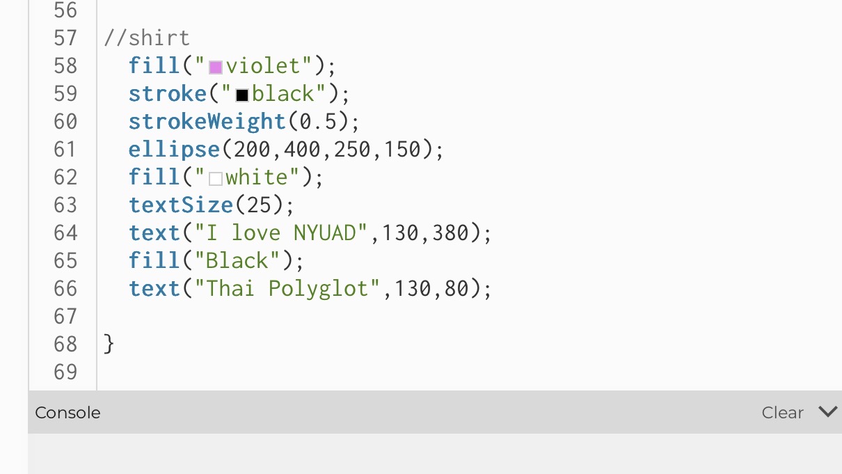
As highlighted code I’m proud of:
The part I am proud of is I was trying to add different parts of my identity to my shirt such as giving purple theme and writing some things that really resonate with me and are part of my identity on the shirt and to be able to write design of NYU shirt on the portrait.
Screenshot
Reflection:
I enjoyed creating my self portrait, alsthought hroguhout the journey I had some difficulties especially at positioning the shapes and getting used to how the gird works, I was able to get through and I think the main thing I struggled was when to apply the noStroke function and finding the right strokeWeight for specific places such as lips etc.
I think in the future what could have been better is after I get better and more used to program I can add some side effects such as animations, and different gimics into the portrait. But overall, I think as the first work it was already pretty fun and I feel proud to create my first very own portrait.
In the user testing most of the user figured out the idea without the need for me to explain; however, there were some pitfalls were the users were a bit confused:
When the two users start to play at the same time and they start to fire they sometimes missed the effects happening and failed to get that the fire portals to the other screen.
The hardware setup I had during testing was not finished so some users failed to get which buttons correspond to which direction.
Button coloring: Some user recommended having the Fire button in different color so they know it’s supposed to perform a different action than movement.
Some users asked about the keyboard controls even though they suspected it’s either gonna be the arrows or WASD. Also the firing button ‘V’ wasn’t clear except for gamers.
What worked really well was the communication between p5 and the neoPixel screen. Once the users got the hang of the game they enjoyed the game so much and the animation of getting hit. They also liked the separation of colors between the player: Yellow and Blue including the fires color coming out of both of them. Some were impressed by the gameplay and how the pixels smoothly switch between the two screens.
To fix the earlier issues I would have a clear instructions page on the game startup that would clarify the controls on both sides and explain scoring system. I would also the core idea of the game to even get the users excited to try it out.
The idea behind A Walk Through Time is to let the viewer control the flow of time with simple hand gestures. When the viewer waves their hand on one side, time moves forward. When they wave on the other side, time reverses. When no one interacts, time pauses. The system changes both the physical world and the digital world at the same time.
The physical clock hand moves using a stepper motor. A growing plant moves up and down using a DC motor and a telescoping cylinder system. On the screen, a surreal p5.js world shows time moving with colors, waves, particles, and a glowing abstract clock. Everything stays in sync and reacts at the same moment. The goal was to create one experience where movement, gesture, and time feel connected.
Project Interaction
Interaction description:
The viewer stands in front of the clock and plant
Two ultrasonic sensors wait for hand gestures
Waving on the right makes the clock tick forward and the plant rise
Waving on the left makes the clock tick backward and the plant collapse
When the viewer steps away, both the clock and plant pause
The p5.js visuals shift to match the state: forward, backward, or paused
How the Implementation Works
The system uses two Arduinos, two motors, two sensors, and a p5.js sketch.
Main Arduino
Reads the left and right ultrasonic sensors
Decides the time state: FORWARD, BACKWARD, or PAUSED
Moves the stepper motor to tick the physical clock
Sends the state through serial as a single character (F, B, or P)
Sends the same data to the second Arduino
Second Arduino
Receives F, B, P
Moves the DC motor to pull or release fishing wire
This grows or collapses a three-layer telescoping plant
p5.js
Reads the same serial data from the main Arduino
Updates the surreal background
Moves particles, waves, arrows, and an abstract glowing clock
Lets the viewer see time flowing
Interaction Design
The interaction is very simple. The viewer uses hand gestures to control time.
Right sensor → Time Forward Left sensor → Time Backward Both or none → Pause
All outputs reinforce this state:
The physical clock hand moves
The plant grows or collapses
The digital world changes color and motion
Arduino Code
Below are the Arduino codes:
#include <Stepper.h>

const int stepsPerRevolution = 2048;
const int ticksPerRevolution = 12;
const int stepsPerTick = stepsPerRevolution / ticksPerRevolution;

Stepper clockStepper(stepsPerRevolution, 8, 10, 9, 11);

enum TimeState { PAUSED, FORWARD, BACKWARD };
TimeState timeState = PAUSED;
TimeState lastSentState = PAUSED;

const int TRIG_RIGHT = 4;
const int ECHO_RIGHT = 5;
const int TRIG_LEFT  = 6;
const int ECHO_LEFT  = 7;

const int DETECT_THRESHOLD_CM = 40;

unsigned long lastTickTime = 0;
const unsigned long tickInterval = 1000;

long readDistanceCM(int trigPin, int echoPin) {
  digitalWrite(trigPin, LOW);
  delayMicroseconds(2);
  digitalWrite(trigPin, HIGH);
  delayMicroseconds(10);
  digitalWrite(trigPin, LOW);
  long duration = pulseIn(echoPin, HIGH, 20000);
  if (duration == 0) return -1;
  return duration / 29 / 2;
}

void sendStateIfChanged() {
  if (timeState == lastSentState) return;
  lastSentState = timeState;
  char c = 'P';
  if (timeState == FORWARD) c = 'F';
  else if (timeState == BACKWARD) c = 'B';
  Serial.write(c);
}

void setup() {
  clockStepper.setSpeed(10);
  pinMode(TRIG_LEFT, OUTPUT);
  pinMode(ECHO_LEFT, INPUT);
  pinMode(TRIG_RIGHT, OUTPUT);
  pinMode(ECHO_RIGHT, INPUT);
  Serial.begin(9600);
}

void loop() {
  unsigned long now = millis();

  long distLeft  = readDistanceCM(TRIG_LEFT,  ECHO_LEFT);
  long distRight = readDistanceCM(TRIG_RIGHT, ECHO_RIGHT);

  bool leftDetected  = (distLeft  > 0 && distLeft  < DETECT_THRESHOLD_CM);
  bool rightDetected = (distRight > 0 && distRight < DETECT_THRESHOLD_CM);

  if (leftDetected && !rightDetected) timeState = BACKWARD;
  else if (!leftDetected && rightDetected) timeState = FORWARD;
  else timeState = PAUSED;

  if (now - lastTickTime >= tickInterval) {
    lastTickTime += tickInterval;
    if (timeState == FORWARD) clockStepper.step(-stepsPerTick);
    else if (timeState == BACKWARD) clockStepper.step(stepsPerTick);
  }

  sendStateIfChanged();
}
const int ENA = 6;
const int IN1 = 5;
const int IN2 = 4;

enum TimeState { PAUSED, FORWARD, BACKWARD };
TimeState state = PAUSED;

byte motorSpeed = 80;

unsigned long lastChangeTime = 0;
const unsigned long maxRunTime = 10000; // 10 seconds

void setup() {
  pinMode(ENA, OUTPUT);
  pinMode(IN1, OUTPUT);
  pinMode(IN2, OUTPUT);
  Serial.begin(9600);
  lastChangeTime = millis();
}

void applyMotorState(TimeState s, byte speed) {
  if (s == PAUSED) {
    digitalWrite(IN1, LOW);
    digitalWrite(IN2, LOW);
    analogWrite(ENA, 0);
  } else if (s == FORWARD) {
    digitalWrite(IN1, HIGH);
    digitalWrite(IN2, LOW);
    analogWrite(ENA, speed);
  } else if (s == BACKWARD) {
    digitalWrite(IN1, LOW);
    digitalWrite(IN2, HIGH);
    analogWrite(ENA, speed);
  }
}

void setState(TimeState newState) {
  if (newState != state) {
    state = newState;
    lastChangeTime = millis();
  }
}

void loop() {
  if (Serial.available() > 0) {
    char c = Serial.read();
    if (c == 'F') setState(FORWARD);
    else if (c == 'B') setState(BACKWARD);
    else if (c == 'P') setState(PAUSED);
  }

  unsigned long now = millis();

  if (state != PAUSED && (now - lastChangeTime >= maxRunTime)) {
    setState(PAUSED);
  }

  applyMotorState(state, motorSpeed);
}
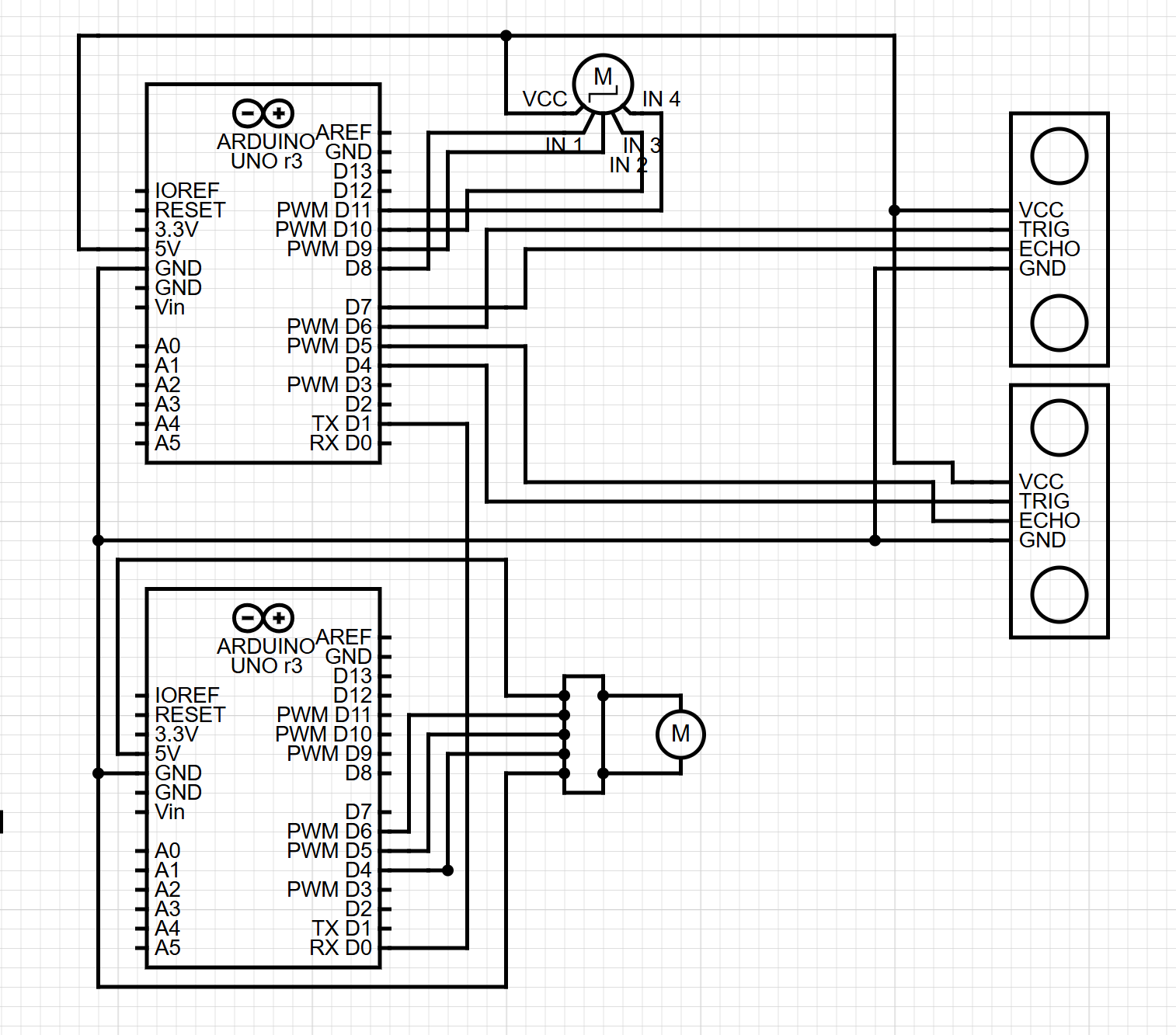
Circuit Schematic
(Diagram made with https://www.circuit-diagram.org/)
breakdown of schematic:
Main Arduino
Ultrasonic Sensor Left
TRIG to pin 6
ECHO to pin 7
VCC to 5V
GND to GND
Ultrasonic Sensor Right
TRIG to pin 4
ECHO to pin 5
VCC to 5V
GND to GND
Stepper Motor (with driver)
IN1 → pin 8
IN2 → pin 9
IN3 → pin 10
IN4 → pin 11
VCC → 5V
GND → GND
Serial Out
TX (pin 1) → RX of second Arduino
Second Arduino (DC Motor Controller)
DC Motor Driver
IN1 → pin 5
IN2 → pin 4
ENA (PWM) → pin 6
Motor output → DC motor
Vmotor → 5V
GND → common ground with Arduin
Serial In
RX (pin 0) → TX of main Arduino
p5.js Code
Reads the serial state from Arduino
Updates the scene
Changes background colors
Moves particles and waves
Animates the digital clock
Shows arrows for direction
Communication Between Arduino and p5.js
Arduino → p5.js
Sends one character:
'F' — forward
'B' — backward
'P' — paused
p5.js reads this using the Web Serial API.
When p5.js sees the character, it updates the digital world.
What I Am Proud Of
I am proud of how everything stays in sync.
The telescoping plant mechanism was hard to build, but it works well and gives life to the piece.
The gesture-based control also feels natural, and most users understand the idea at once.
How This Was Made
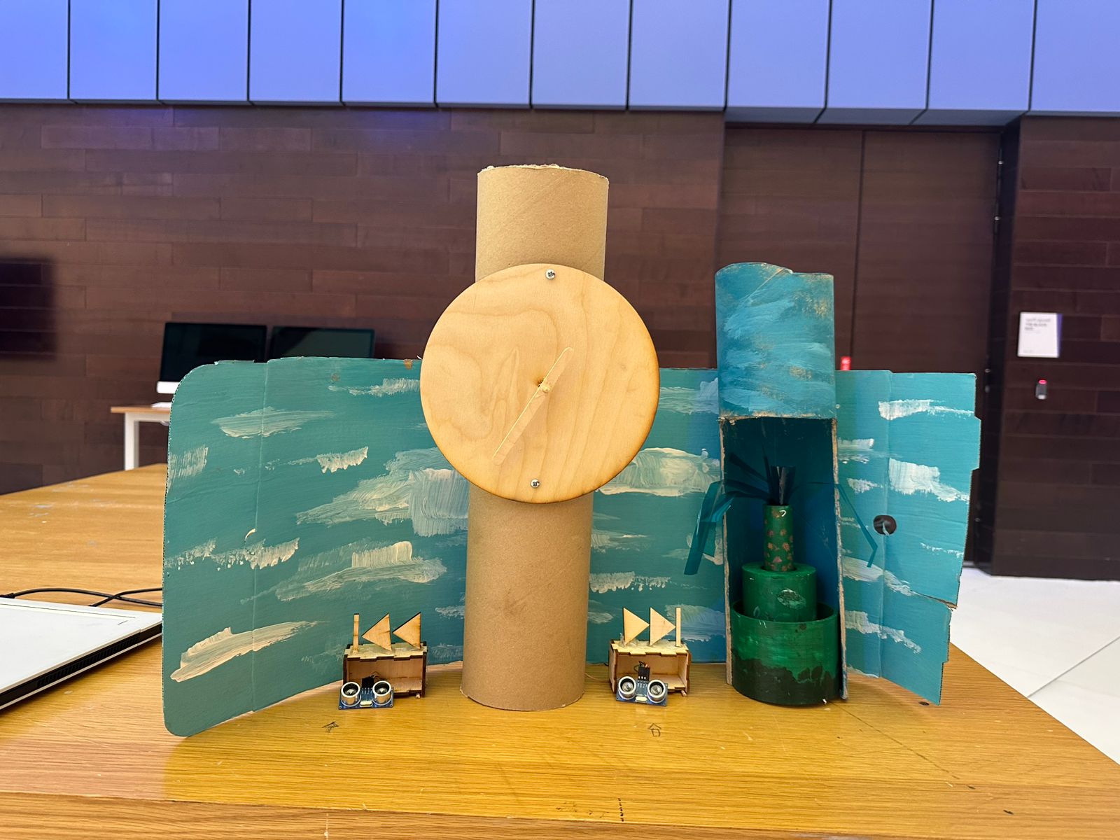
The clock was laser cut and screwed into a cardboard cylinder. I used an ice cream stick for the hand, which was connected using a skewer to the stepper motor. The boxes for the ultrasonic sensors were laser cut, and I got the design from boxes.py. For the fast forward and rewind icons, I designed them in Illustrator and then laser cut them. I got the idea for the telescoping cylinder from a YouTube short (https://www.youtube.com/shorts/99a4RUlUTm0), and I made a much simpler version that I 3D printed. I used another cardboard cylinder that I cut open to place the plant in and attach the DC motor and wheel at the top. I used acrylic paint, with help from an art major friend, to paint a background scene with the plant and sky.
The p5.js code was written through many tests and changes to connect smoothly with the Arduino using Web Serial. The designs for the scene, the clock visuals, and the interaction layout were made in small steps until everything felt right. The writeup was also done in simple clear language to explain the full system. All media was either created by me, painted by a friend, laser cut from my designs, or made using free online tools.
Areas for Future Improvement
The clock could be painted with a wooden-style finish to look more complete. I also still want to explore the original rotary sensor idea. The plan was to let the user manually rewind the clock by hand, and the system would detect this and move backward. I tested this with gears connecting the rotary sensor to the stepper motor, but the motor was too weak or the gears did not line up. I want to try again with stronger parts.
Finally, while the p5.js visuals look good and support the project, I feel there may be more ways to integrate the digital space with the physical movement. This is something I want to improve in the future.
I have conducted the user testing for the project, and the reactions were very positive. Most users understood the main idea right away. When the clock hand moved forward, they saw it as time moving forward. When it moved backward, they understood that time was reversing. This was a good sign that the core interaction is intuitive and does not need much explanation.
The gesture control also made sense to most people, but a few were unsure at first about which sensor to wave their hand over. To make this clearer, I decided to laser cut simple icons for fast forward and rewind and attach them to the ultrasonic sensors. This small change makes the mapping between gesture and action much more obvious.
One interesting issue that came up during testing was the behavior of the plant mechanism. The DC motor pulls fishing wire that extends a telescoping plant, and it collapses when the motor goes in reverse. Some users kept reversing time for too long, which caused the wire to unwind so far that it started rolling in the opposite direction. This made the plant rise again by mistake. Another related problem was users sending the plant up too high until it almost reached the motor.
To address this, I am adding a failsafe to the DC motor logic. The system will now prevent the motor from spinning in the same direction for too long. This will keep the fishing wire from fully unspooling and will protect the telescoping structure from being pulled too far up. This fix makes the physical system more reliable and safer for open interaction
A Walk Through Time is an interactive artwork that combines a physical clock, motion sensors, a DC motor, a stepper motor, and a digital surreal time-scape made in p5.js. The goal is to let the viewer control the flow of time with simple gestures, and watch both the physical world and the digital world respond in sync. When the viewer waves a hand on one side, time moves forward. When the viewer waves a hand on the other side, time moves backward. When no one is interacting, time pauses.
Arduino: Design and Behavior
The hardware side uses:
Two ultrasonic sensors
A stepper motor that drives a physical clock hand
A DC motor that rotates forward or backward depending on the state
A communication link to p5.js through Web Serial
A second Arduino that receives the state and drives the DC motor
Inputs (Arduino)
Left ultrasonic sensor
Detects a hand or body close to it
If only the left sensor sees something, time moves backward
Right ultrasonic sensor
Detects a hand or body on the right side
If only the right sensor sees something, time moves forward
Both sensors together or none
Time enters a paused state
The Arduino reads both sensors and decides one of three states: FORWARD, BACKWARD, PAUSED
Outputs (Arduino)
Stepper motor movement
Moves a physical clock hand
A full rotation is broken into 12 “ticks”
In FORWARD state the stepper ticks clockwise
In BACKWARD state the stepper ticks counterclockwise
In PAUSED state it holds still
Serial output sent to p5.js
The Arduino sends a single character representing the state:
‘F’ for forward
‘B’ for backward
‘P’ for paused
Serial output to the second Arduino (DC motor controller)
The same state characters (F, B, P) are sent out
DC Motor Arduino
The second Arduino receives the state from the first one:
‘F’ → DC motor spins forward
‘B’ → DC motor spins backward
‘P’ → DC motor stops
p5.js: Design and Behavior
The digital part is a surreal, dreamlike time-space. It reacts in real time to the state coming from Arduino. The design uses motion, color shifts, particles, waves, ripples, and a glowing abstract clock.
Inputs (p5.js)
Serial data from the Arduino
Reads incoming characters: F, B, or P
Updates timeState
Applies visual changes based on the state
Keyboard fallback for testing
F B P keys switch states if Arduino is not connected
Behavior of the digital scene
The scene changes in several ways depending on the state, reflecting time going forward, backwards, or stopped.
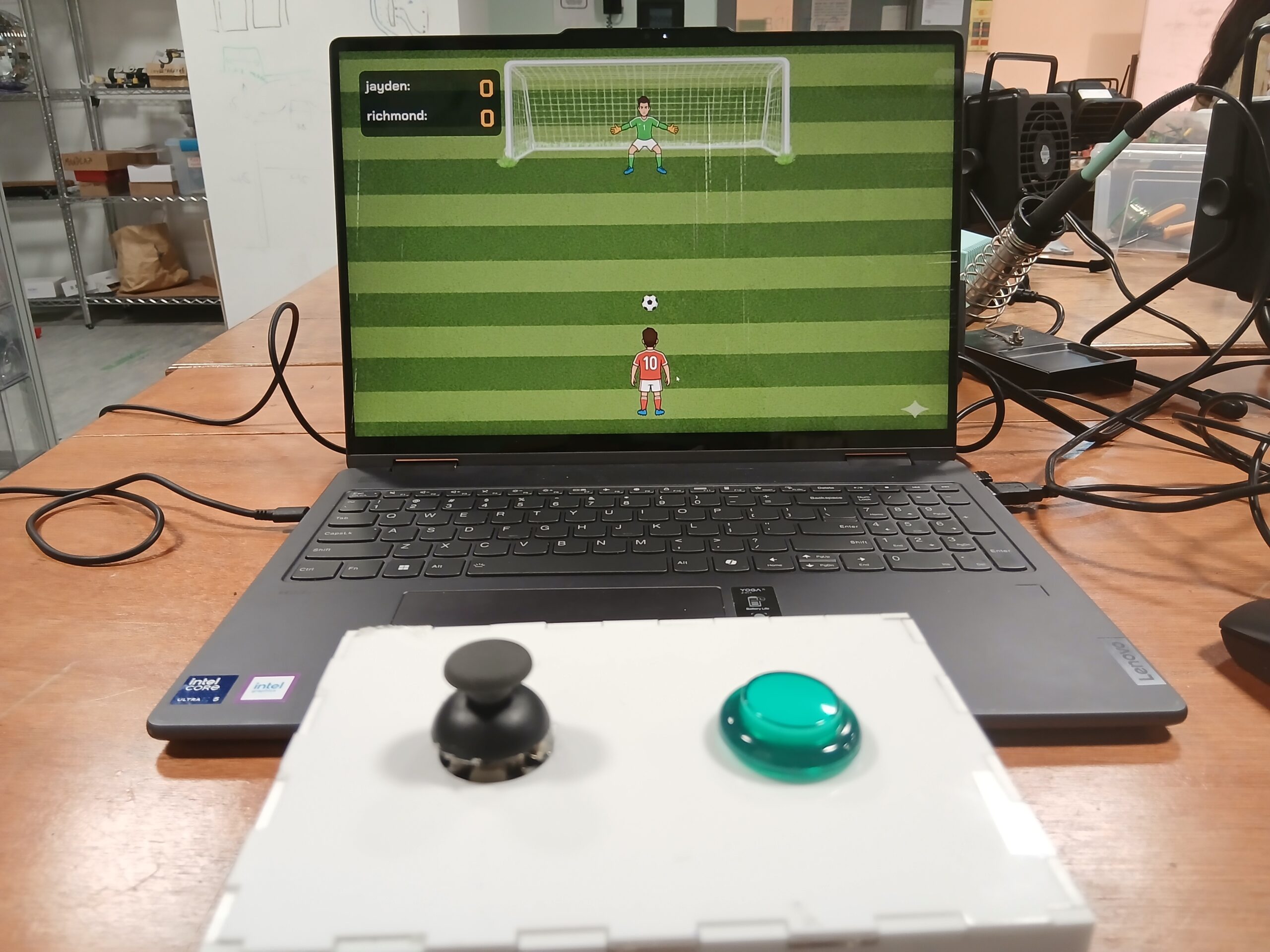
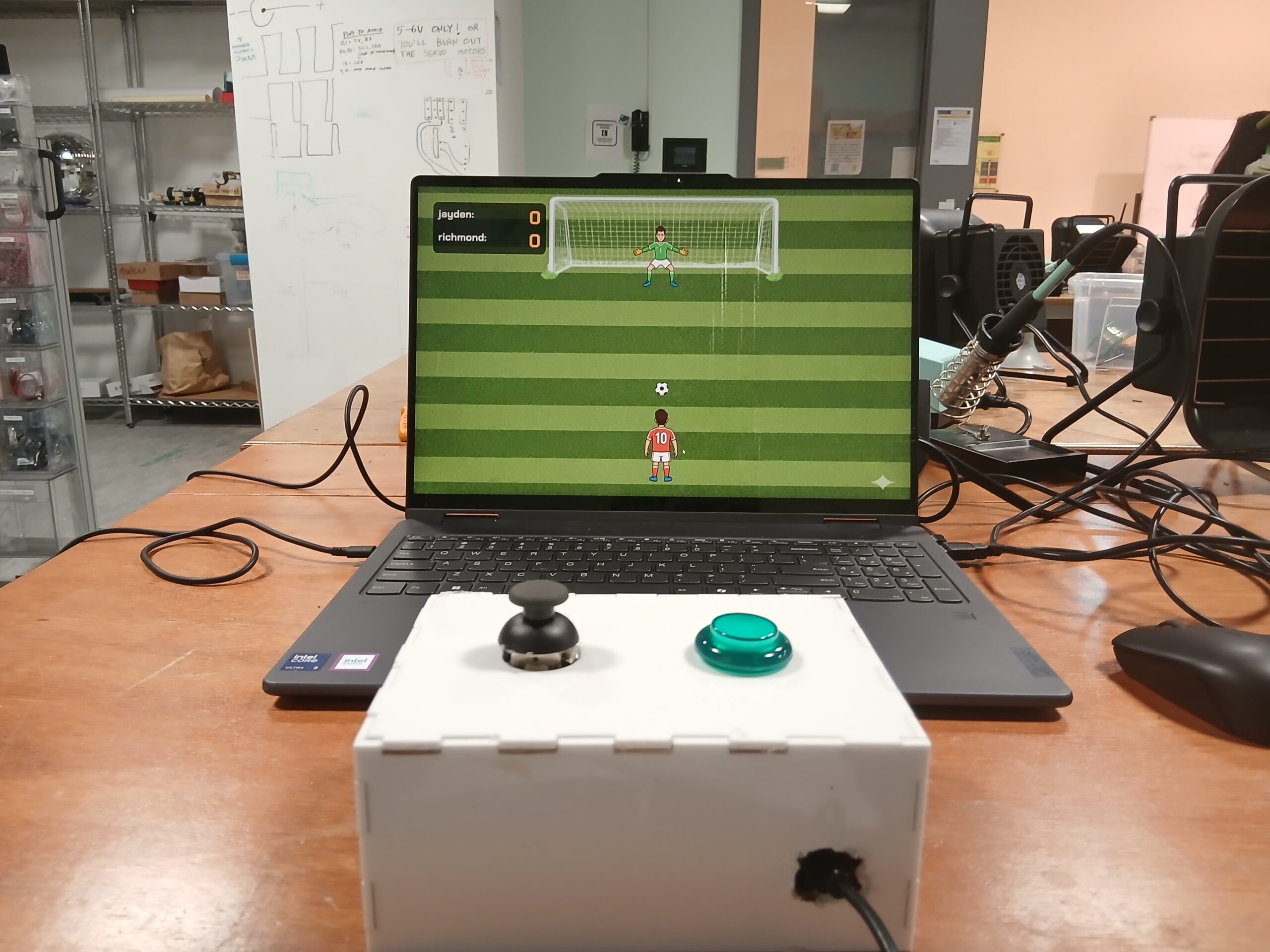
For my final project in Intro to IM, I created KICK ‘N’ SAVE, an interactive penalty-kick game that combines Arduino hardware, a joystick + arcade button, p5.js animation, and machine-learning hand-tracking using ML5’s Handpose model.
The idea was to create a soccer experience where the player controls the shooter with a physical joystick, while the goalkeeper is controlled by hand gestures picked up by a webcam. This combination of digital and physical interaction makes the gameplay energetic, intuitive, and fun for spectators.
The goal was to build something that feels like an arcade mini-game, is simple to understand immediately, and still feels alive because of the hand-controlled goalkeeper.
KICK ‘N’ SAVE involves two simultaneous interactions:
Shooter (player 1): Uses a physical joystick
Tilt ← → to select shot direction
Press the push button to shoot
LED flashes green if a goal is scored
Goalkeeper (player 2): Controlled by hand gestures using a webcam
Move hand to left/center/right
ML5 Handpose tracks the index fingertip
Keeper smoothly lerps toward the detected zone
Attempts to block the shot
The design intentionally creates a duel between physical and digital control.
Arduino Code:
The Arduino handles:
Joystick left/middle/right detection
Button press detection for shooting
LED flashing animation when p5.js sends ‘G.’
Serial communication to send ‘L’, ‘M’, ‘R’, and ‘S’ to p5.js
Code Snippet
// PIN DEFINITIONS

const int xPin = A0;        // Joystick XOUT
const int buttonPin = 2;    // Joystick Button (SEL)

const int GREEN_LED_PIN = 10; // Green LED (NOW: Arcade Button Light)

// JOYSTICK THRESHOLDS

const int thresholdLow = 400;
const int thresholdHigh = 600;

// State variables
String lastDirection = "M";  // Start in middle
int lastButtonState = HIGH;

// LED flash duration (1 second flash)
const int LED_FLASH_TIME = 1000;

void setup() {
  Serial.begin(9600);

  pinMode(buttonPin, INPUT_PULLUP);

  pinMode(GREEN_LED_PIN, OUTPUT);

  digitalWrite(GREEN_LED_PIN, LOW);
}

void loop() {

  // A. HANDLE LED COMMANDS FROM p5.js
  if (Serial.available() > 0) {
    char c = Serial.read();

    if (c == 'G') {
      digitalWrite(GREEN_LED_PIN, HIGH);
      delay(LED_FLASH_TIME);
      digitalWrite(GREEN_LED_PIN, LOW);
    }
    else if (c == 'R') {
      // Do nothing
    }
  }

  // B. READ JOYSTICK X-AXIS

  int xVal = analogRead(xPin);
  String currentDirection;

  if (xVal < thresholdLow) currentDirection = "L";
  else if (xVal > thresholdHigh) currentDirection = "R";
  else currentDirection = "M";

  if (currentDirection != lastDirection) {
    Serial.println(currentDirection);
    lastDirection = currentDirection;
  }

  // C. READ JOYSTICK BUTTON (SHOT)
  int buttonState = digitalRead(buttonPin);

  if (buttonState == LOW && lastButtonState == HIGH) {
    Serial.println("S");
  }

  lastButtonState = buttonState;

  delay(50);
}
Here is the link to the full code on GitHub: Github
p5.js Code:
The p5.js sketch handles:
Rendering the game visuals
Animating the ball based on the joystick-chosen direction
Keeper movement driven by ML5
Collision detection
Sending ‘G’ or ‘R’ back to Arduino
Embedded sketch
Parts of the Project That I’m Proud of
One of the things I’m most proud of in this project is how naturally the hybrid interaction system came together. The combination of a physical joystick for the shooter and ML5 hand tracking for the goalkeeper created a dynamic, two-sided experience that feels genuinely interactive and different from typical p5.js games. I’m also especially proud of the smooth goalkeeper movement—using lerp() to reduce jitter made the keeper feel responsive yet realistic, which dramatically improved gameplay. I’m also pleased with the UI design, especially the cartoon-style intro page, which gives the game a professional and cohesive look. On the technical side, achieving stable serial communication between Arduino and p5.js—with no dropped signals—was a big accomplishment and made the hardware and software feel seamlessly connected. Altogether, these elements make the project feel less like a school assignment and more like an actual mini-game someone might find in an arcade or mobile app.
Guided merging of joystick logic with animation logic
Assisted in writing ML5 code for controlling the goalkeeper in the three directions
Gemini
Helped generate images used for the project (intro page image, goalkeeper image, shooter image)
Challenges Faced & How I Overcame Them
1. ML5 Handpose jitter
Solved using lerp() for smoother movement
Added 3-zone classification instead of direct x-values
2. Joystick sending multiple repeated values
Fixed by only sending direction when it changes
3. Arduino errors from invisible characters
Caused by stray UTF-8 spaces
Solved by rewriting the affected lines manually
4. Serial communication timing issues
Added delays + ensured consistent baud rate
Verified using the p5 serial monitor
5. Resizing issues
Used scaleFactor everywhere based on the window height
Updated positions inside windowResized
Areas for Improvement
Looking ahead, there are several exciting improvements I’d love to bring into future versions of this project. One of the biggest upgrades would be enhancing the core game mechanics – especially by adding variable shot power so the ball’s speed and curve depend on how long the shooter holds the button. This small change would instantly add depth and skill to the gameplay. I also want to rethink how the goalkeeper reacts by introducing a realistic “dive” mechanic that forces quick decisions instead of constant tracking, making the challenge more balanced and intense. On the user experience side, adding a subtle aiming line for the shooter and a clear tracking-zone guide for the goalkeeper would solve most of the confusion players currently face. Technologically, expanding the serial communication to include haptic feedback or LED signals would make the hardware feel more alive and connected to the game. And finally, introducing polished animations – like a proper kick sequence or a dramatic save – as well as a slight 3D-style pitch perspective would elevate the visual experience far beyond the current prototype. All together, these improvements could transform the game from a fun demo into a fully immersive, replayable mini-sports experience.
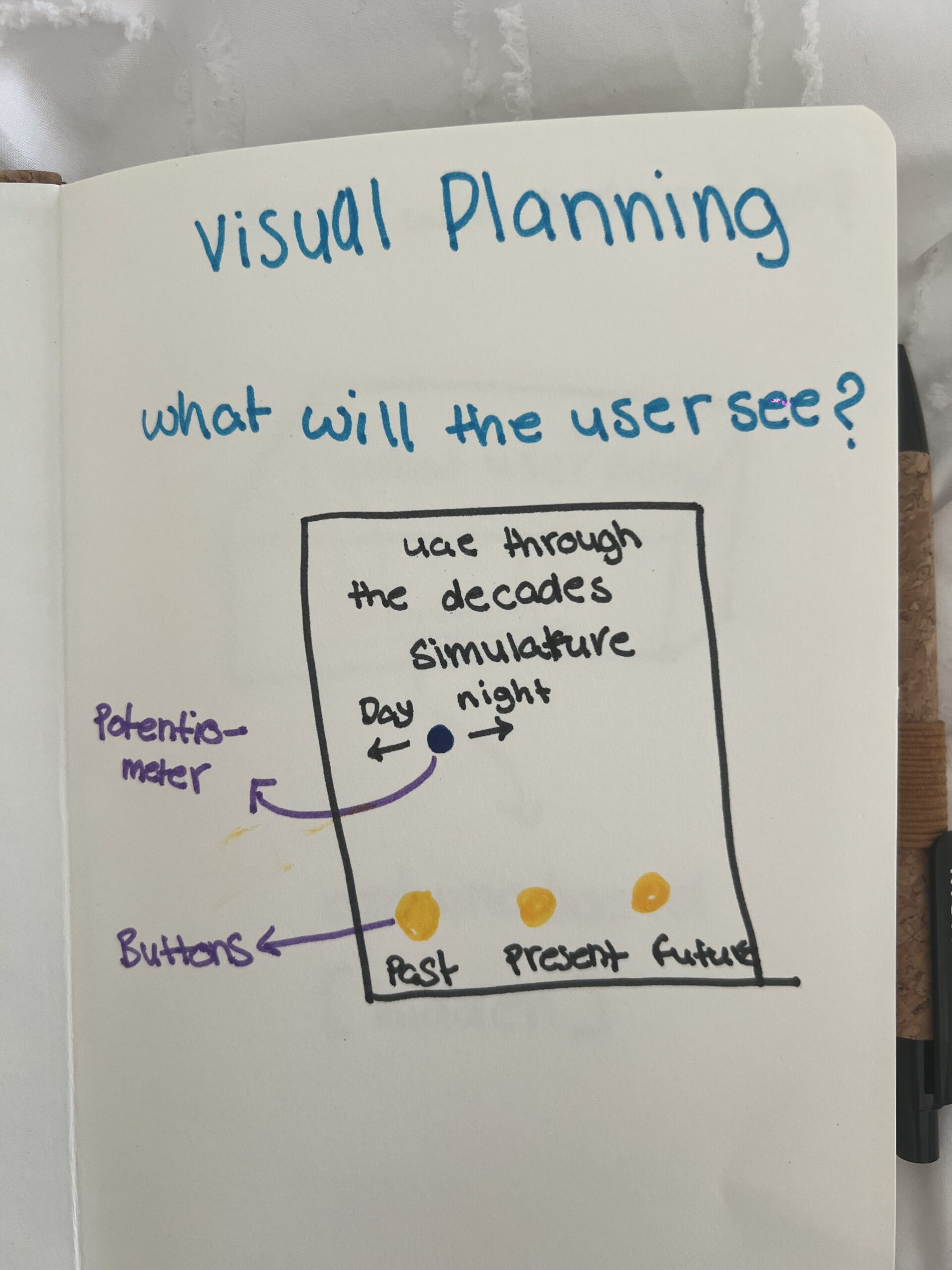
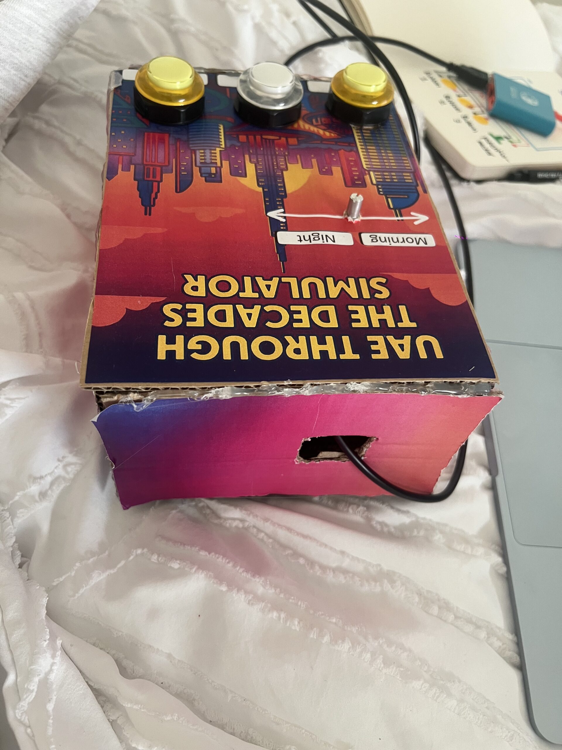
My project is a physical digital simulator that showcases the UAE across three eras: the past, the present, and the imagined future. The idea came from listening to my grandfather’s stories about how he used to live, and how different life is now. Seeing how quickly the UAE developed made me wonder how the future will look. I wanted to create an experience where people can explore this progression visually by interacting with a real physical device.
The simulator lets users switch between the three eras using physical buttons, and then cycle through multiple images for each era. A potentiometer controls the transition between morning and night, allowing people to view each scene in two different lighting conditions. Overall, the goal of my concept is to let users “travel through time” and explore how the UAE evolved and how it might continue to evolve.
How the Implementation Works
The project works through a simple but effective communication between Arduino and p5.js:
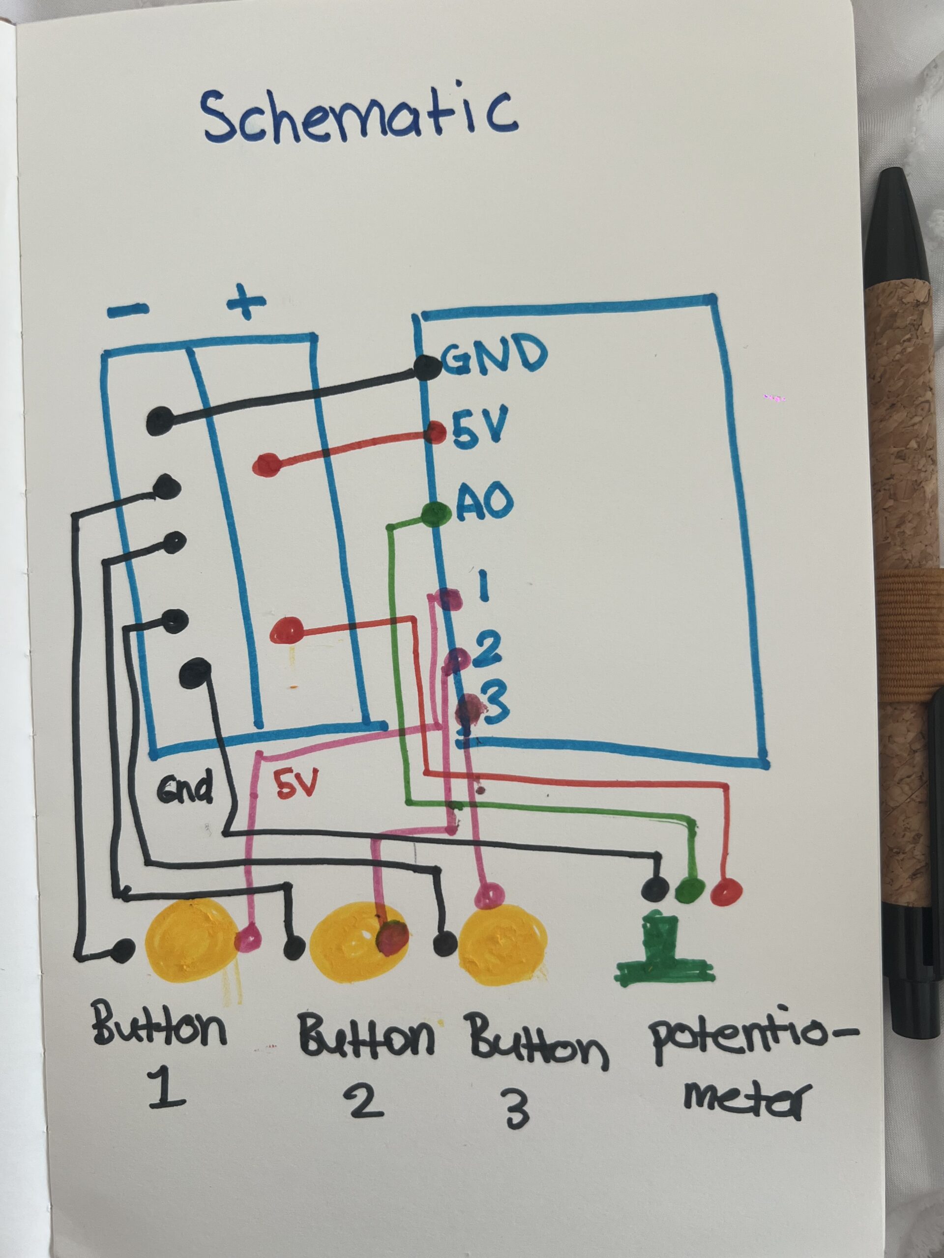
• The Arduino has three buttons (Past, Present, Future) and a potentiometer.
• When the user presses a button, Arduino sends data to p5.js identifying the era and which image should appear.
• When the user turns the potentiometer, Arduino sends a number from 0–1023, which p5.js interprets as morning vs. night.
• p5.js displays the correct image from a set of 18 total images (3 eras × 3 photos × 2 lighting versions).
• Everything is controlled physically the user doesn’t interact with the laptop at all after connecting.
I intentionally kept the interaction simple so it would be easy for younger users (including my younger brother) to understand instantly.
The interaction is entirely physical and designed to be intuitive:
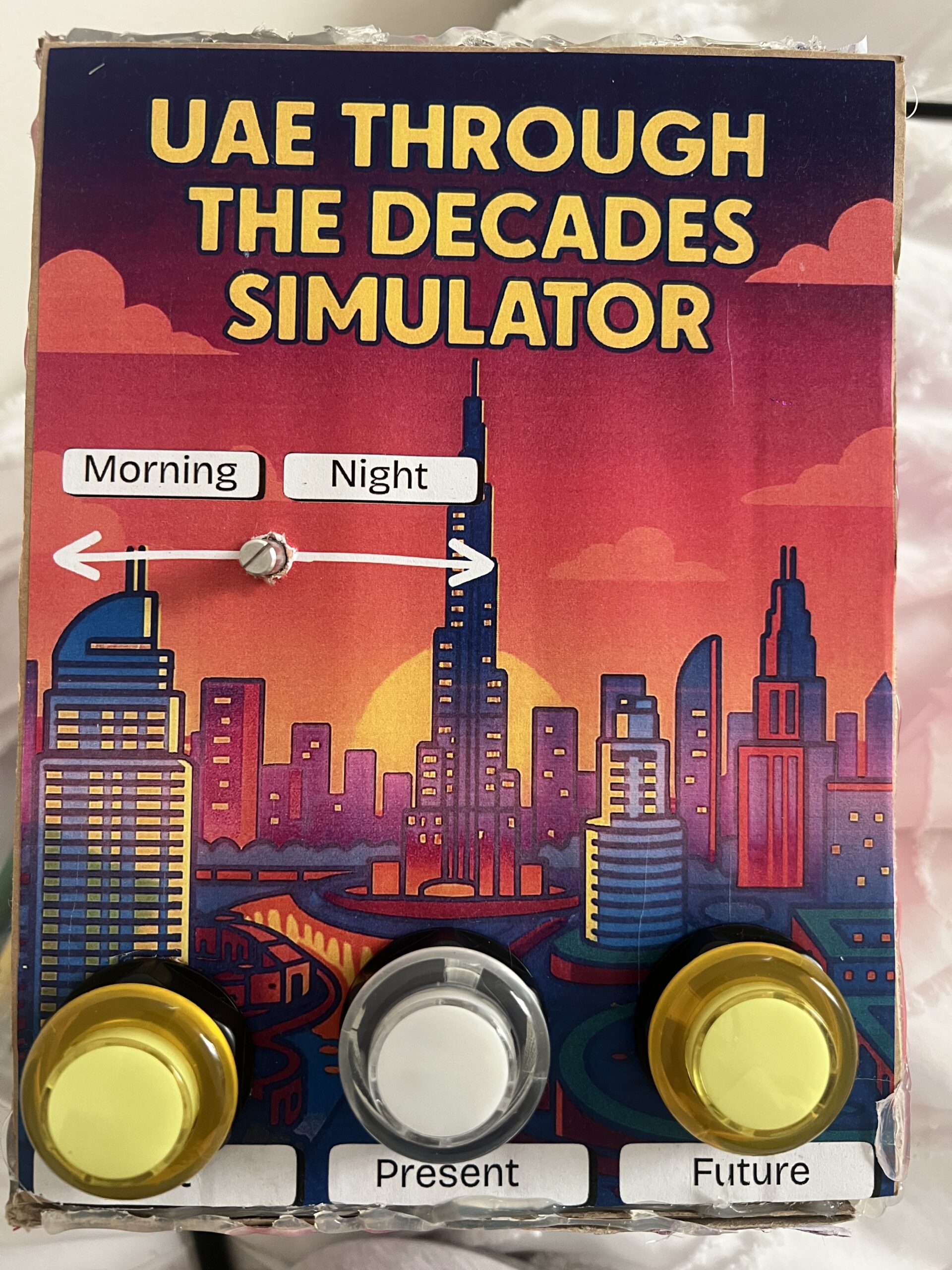
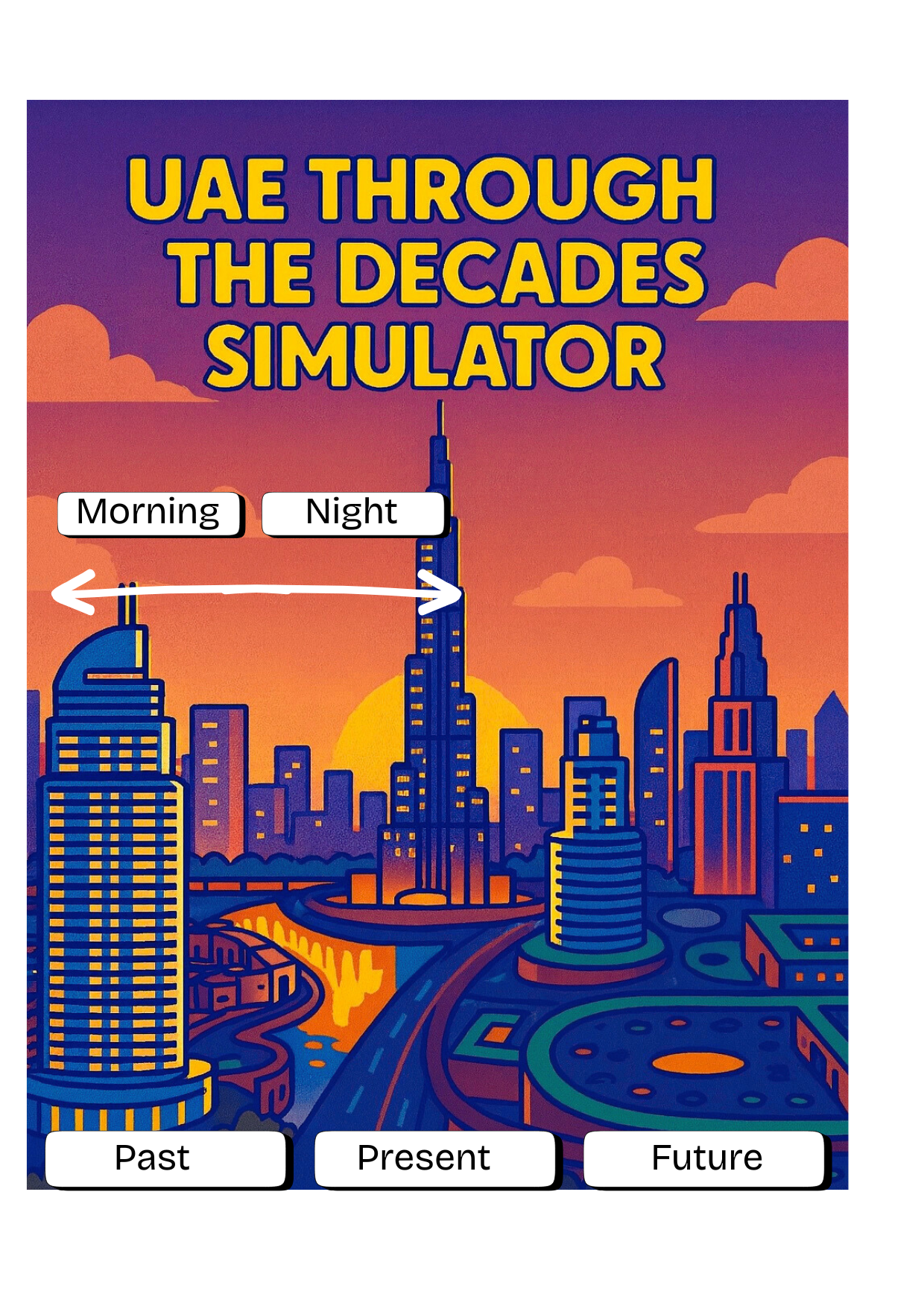
• Three buttons, each labeled clearly: Past, Present, Future.
• Pressing a button cycles through three images per era.
• The potentiometer smoothly switches the scene from morning to night.
• No touchscreen interaction the laptop only displays the images.
My goal was to make the mapping extremely obvious. Every person who tested the project understood the basic interaction immediately because the controls directly match the results on the screen. The only part that took a few seconds to discover was that each button can be pressed multiple times to cycle through all images, but users figured it out naturally by experimenting.
Description of Arduino Code (with link/summary)
The Arduino code is fairly simple. It:
• Reads the state of three buttons using INPUT_PULLUP
• Reads a potentiometer value (0–1023)
• Tracks which era is active
• Tracks how many times the user pressed each button (to rotate through 3 images)
// pins
const int pastBtn    = 2;   // Button 1 Past UAE
const int presentBtn = 3;   // Button 2  Present UAE
const int futureBtn  = 4;   // Button 3  Future UAE
const int potPin     = A0;  // Potentiometer day/night

// variables
int era = 0;       // 0 = past, 1 = present, 2 = future
int imgIndex = 0;  // 0, 1, 2

bool pastPrev    = HIGH;
bool presentPrev = HIGH;
bool futurePrev  = HIGH;

void setup() {
  Serial.begin(9600);

  pinMode(pastBtn, INPUT_PULLUP);
  pinMode(presentBtn, INPUT_PULLUP);
  pinMode(futureBtn, INPUT_PULLUP);
}

void loop() {
  bool pastState    = digitalRead(pastBtn);
  bool presentState = digitalRead(presentBtn);
  bool futureState  = digitalRead(futureBtn);

  if (pastPrev == HIGH && pastState == LOW) {
    era = 0;
    imgIndex = (imgIndex + 1) % 3;
    sendData();
    delay(200);
  }

  if (presentPrev == HIGH && presentState == LOW) {
    era = 1;
    imgIndex = (imgIndex + 1) % 3;
    sendData();
    delay(200);
  }

  if (futurePrev == HIGH && futureState == LOW) {
    era = 2;
    imgIndex = (imgIndex + 1) % 3;
    sendData();
    delay(200);
  }

  pastPrev    = pastState;
  presentPrev = presentState;
  futurePrev  = futureState;

  //  update for the potentiometer
  static unsigned long lastSend = 0;
  if (millis() - lastSend > 200) {
    sendData();
    lastSend = millis();
  }
}
//serial
void sendData() {
  int timeVal = analogRead(potPin); // 0–1023

  Serial.print(era);
  Serial.print(",");
  Serial.print(imgIndex);
  Serial.print(",");
  Serial.println(timeVal);
}
Description of p5.js Code
The p5.js code handles:
• Displaying all 18 images
• Fading transitions between images
• Scaling images to full screen
• Playing different audio for each era
• Reading serial data from the Arduino
• Switching between three states:
• Connect screen
• Intro screen
• Simulator screen
The images are the main content 18 total files (6 per era). They were made by taking real images of the UAE and using generative AI tools to convert them into cartoon versions. p5.js simply loads these files and displays them according to the physical input.
Communication Between Arduino and p5.js
The communication uses Web Serial:
1. The user clicks once to connect.
2. The browser opens a Serial Port window.
3. After selecting the Arduino, p5.js starts receiving lines of text like:
4. p5.js splits the line into:
• era (0 = past, 1 = present, 2 = future)
• imageIndex (0, 1, or 2)
• timeVal (0–1023, used for day/night)
Every change on the physical device immediately updates the display on screen.
It feels similar to using a game controller or a Joy-Con everything is physical, and the screen responds instantly.
What I’m Proud of
I am most proud of how clean and professional the final project looks.
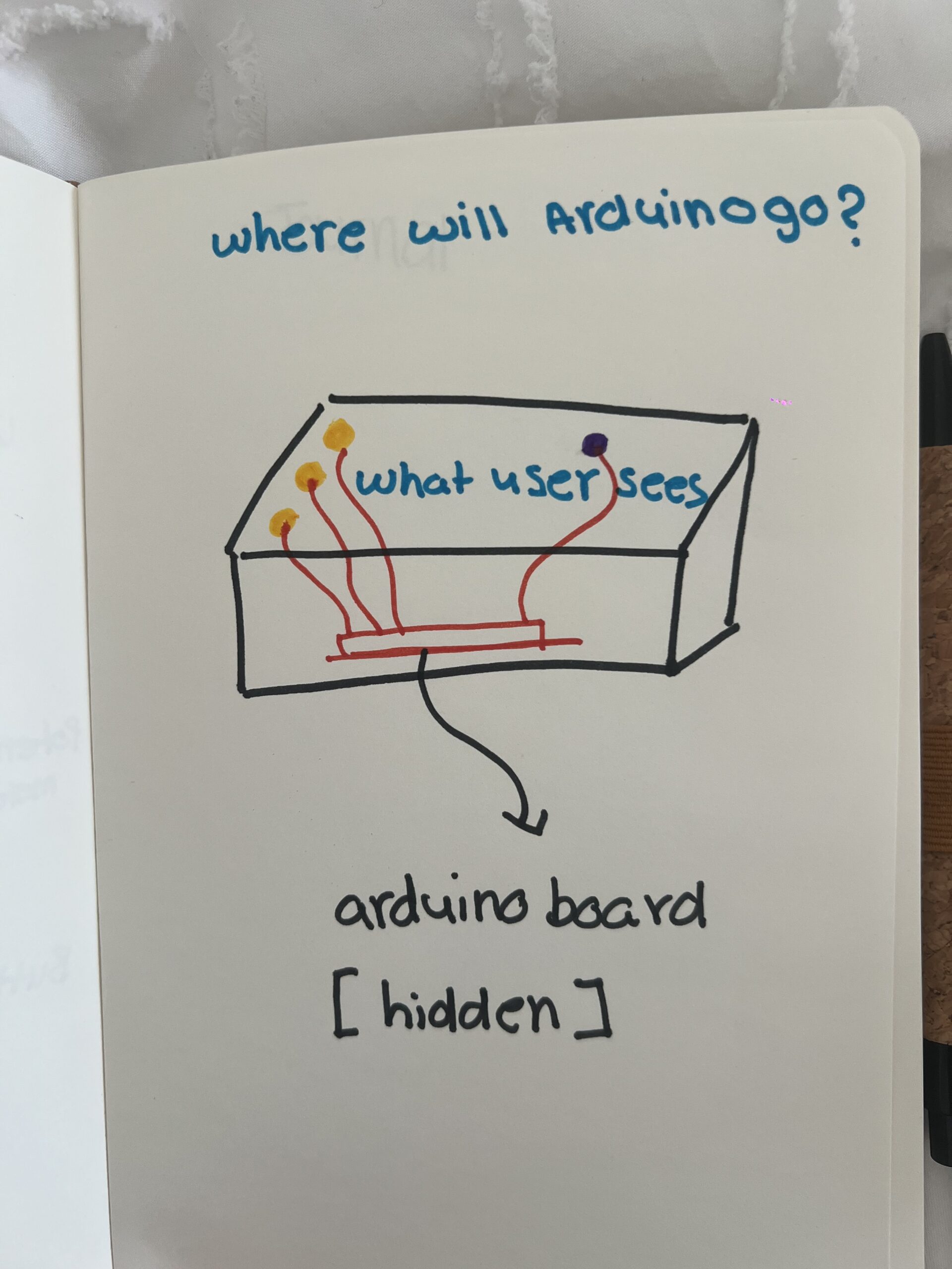
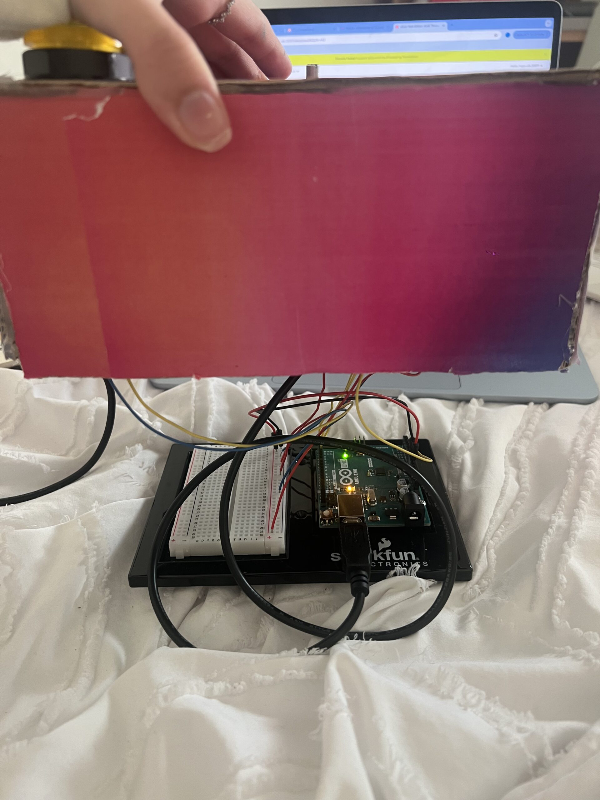
You can’t see any of the wiring I hid everything neatly inside the cardboard housing. The labeling, colors, and layout make the experience very user-friendly. I’m also proud of the fact that people were able to figure it out without me saying anything. When I stepped back and just observed, I realized the design communicated itself very clearly, which was exactly my goal.
Looking back at the entire process, I’m genuinely proud of how much I accomplished and how much I learned along the way. At first, organizing all the images felt extremely tedious because I had so many files 18 images total, each with morning and night versions. I also made a small mistake in the naming of the files, and that one mistake made the whole program stop working. I kept getting errors and I couldn’t figure out why. I had to go through each image name one by one, and because the names were long and similar, it was hard to spot the issue. It took me a very long time to fix something that seemed so small, but once I finally found the mistake and everything started working again, it felt very rewarding. I’m also incredibly proud of the physical construction, especially the welding. This was my first time ever welding metal, and it honestly took me one full hour just to weld the first button. The wires kept slipping, the metal didn’t stick properly, and I felt like I was never going to get it. But after doing it over and over, I suddenly got the hang of it, and by the end I was welding each button in about five minutes. Learning a skill like that felt like a big milestone. It really made me feel like I gained a new hands-on skill something I had never tried before in my life.
In the end, the project came together in a way that made me really proud. The wiring is completely hidden, the design is clean and professional-looking, and people were able to interact with it without any instructions. Seeing the final result made all the tedious moments worth it, and it also made me feel more confident in both my coding and physical building abilities.
How This Was Made
I built the physical simulator using:
Cardboard and printed graphics
Buttons and a potentiometer
Metal wires (which I welded for the first time and it took me one full hour to weld my first button!)
Arduino and jumper wires
Use of Generative AI
I used AI for visual styling. I first found real photos of the UAE (past, present, and future concept images) and then used AI tools to convert them into cartoon-style illustrations. This helped give the project a consistent artistic style.
I also used AI to help me debug an issue in my p5.js code I sent it the error message and it told me that most probably one of my files name was not the same name I put in the code, which was correct in naming one of my images I accidentally made one of the letters capital and in my code it was lowercase so the code wasn’t running
Design
I used Canva to design the visual aspect
Code Writing & Design
Most of the code is simple enough that I was able to write it myself, but I watched a few YouTube videos to help me understand specific parts, such as Web Serial and Arduino button logic:
Sound source
https://pixabay.com/sound-effects/search/mp3/
Areas for Future Improvement
In the future, I would like to:
• Add more images per era to make the experience richer
• Include more interactive controls, not just day/night
• Maybe add animated elements like moving clouds or cars
• Improve the instruction screen so that users immediately know they can press each button multiple times
• Add richer audio or voice narration explaining the history of the UAE
1. Are they able to figure it out? Where do they get confused and why? Do they understand the mapping between the controls and the experience?
When I tested my project with different people, I noticed that the overall interaction was very easy for them to understand. The three buttons were clearly labeled “Past,” “Present,” and “Future,” and the potentiometer automatically felt like a control for changing between morning and night. I designed the layout to be very straightforward on purpose because I wanted even younger users like my younger brother to be able to use it without help.
When I let my friend try it without any instructions, she was able to figure out the basic interaction immediately. She understood the mapping between the labeled buttons and the changes on the screen. The design helped guide her because I placed each label directly under the button, and the screen clearly showed the UAE environment changing based on the chosen era.
The only part that took her a bit longer to discover was that each button could be pressed multiple times to cycle through three different images. She eventually figured it out on her own by experimenting and playing with it. Most of my friends had the same experience: they understood the main controls right away, but it took some time to realize the buttons could be pressed repeatedly to see more images. Even though it wasn’t immediately obvious, they still learned it naturally without any instructions from me, which made me feel confident that the interaction was intuitive.
2. What parts of the experience are working well? What areas could be improved?
Overall, the system worked exactly the way I intended. The clear labels, simple design, and straightforward interaction made the experience smooth for almost everyone who tested it. People enjoyed seeing the UAE change across the past, present, and future, and the morning night movement using the potentiometer worked very naturally.
However, one area I think I could improve is adding a small instruction guide or a simple on-screen hint. Even though most people figured it out, some took longer to realize they could press each button multiple times to explore all the images. A very small, minimal instruction (like “Press again to see more”) could make the experience clearer from the very beginning.
Other than that, the core interaction and design felt strong and easy to understand.
3. What parts of your project did you feel the need to explain? How could you make these areas clearer to first-time users?
At first, I thought I needed to explain everything especially the fact that there are multiple images per era. But when I stepped back and watched people interact with it without saying anything, I realized that they figured it out on their own. The project ended up being much more self-explanatory than I expected, and most of the clarity came from the very clean design and labeling.
The only part that consistently required a moment of discovery was the “multiple press” feature. To make that clearer for first-time users, I could add a small visual cue or a short line of text somewhere on the screen that hints that the user should “press to cycle through images.” This would make the experience smoother for absolutely everyone, even if they don’t experiment as much.
But overall, user testing showed me that the project communicates itself pretty naturally, and I didn’t really have to explain much which was exactly the kind of interaction experience I wanted to create.