CONCEPT
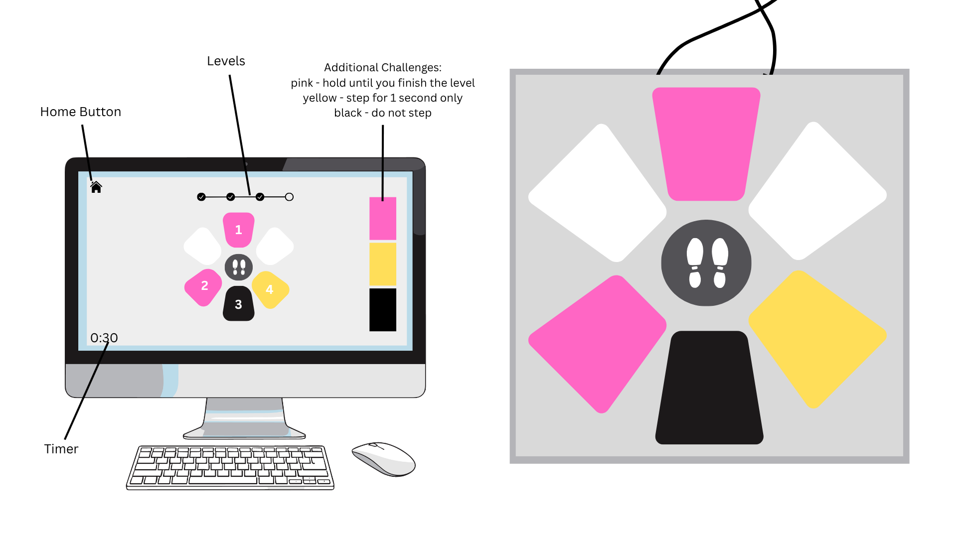
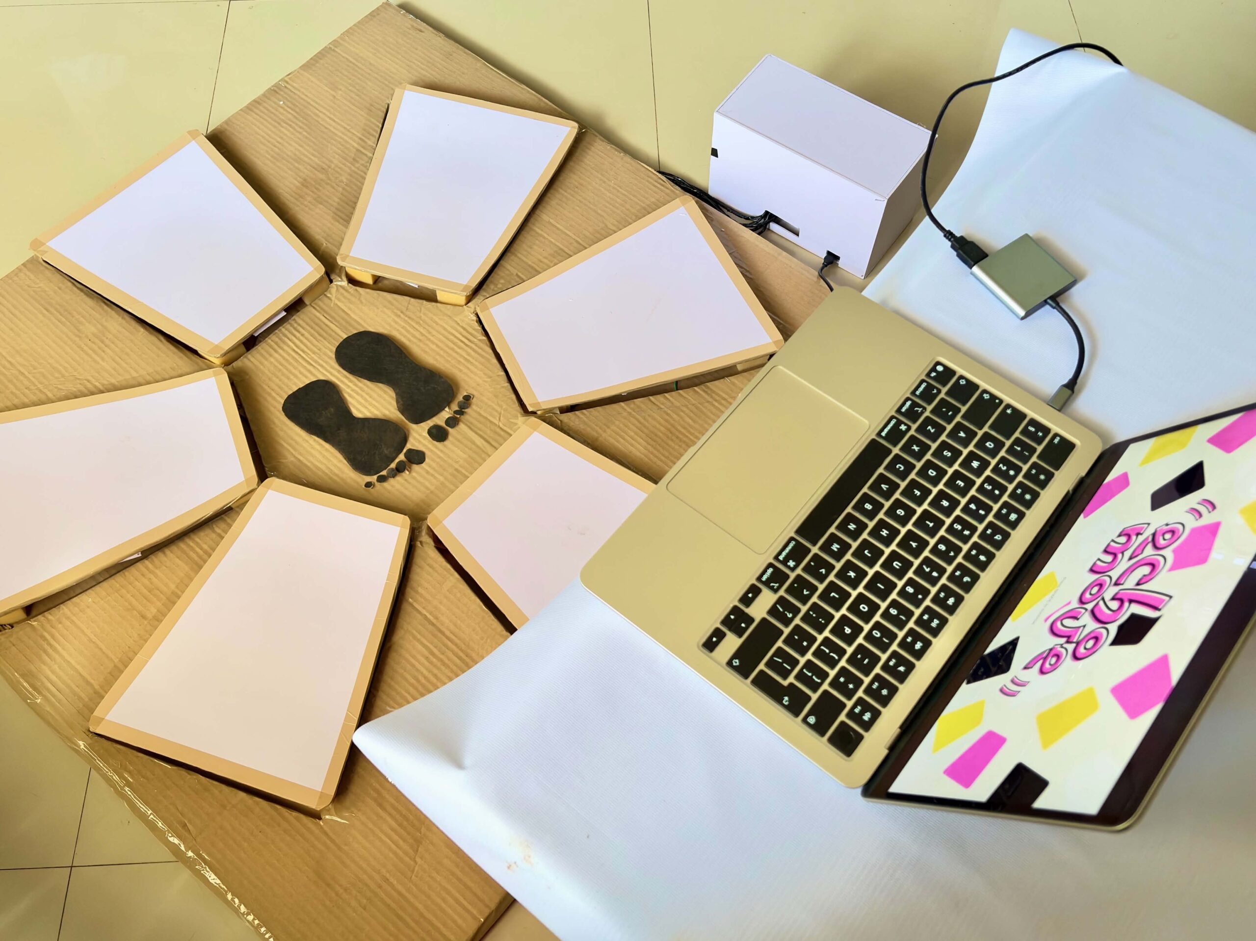
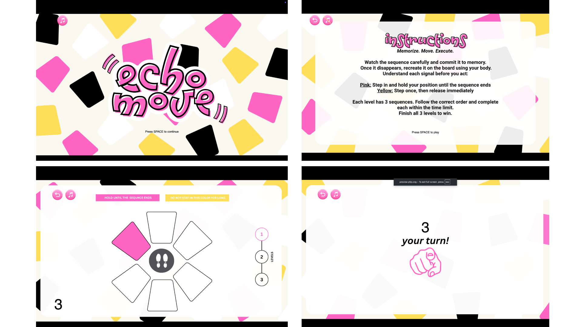
In Echo Move, players are shown a sequence of colored tiles on screen for a few seconds. Once it disappears, they have to recall and perform the sequence using any part of their body on the “Echo Move Board,” which is connected to an Arduino. The challenge is to remember the information and use it accurately on time.
 The phy
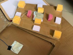 sical board it
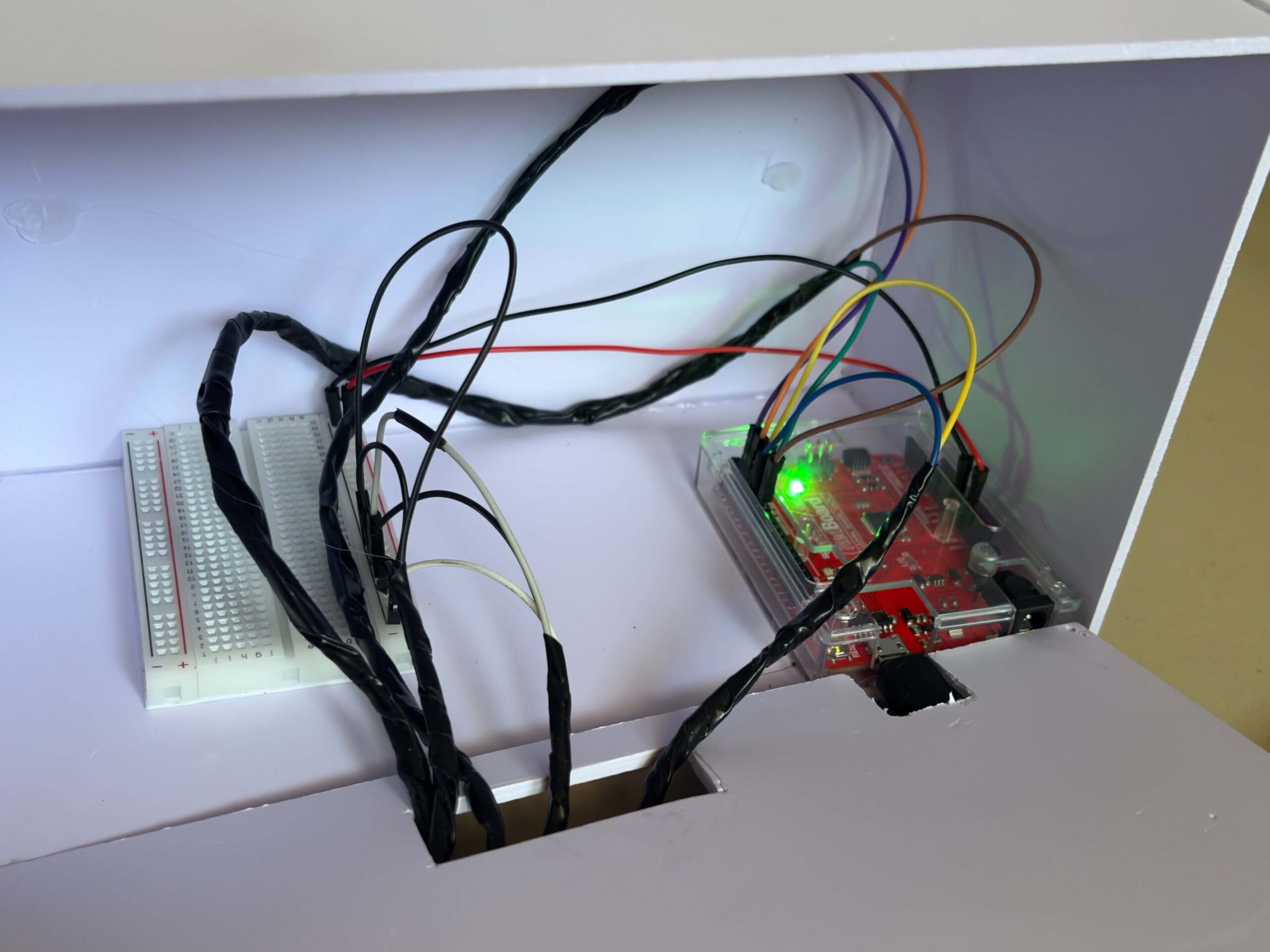 self has no colors, only neutral zones. All cues come from the screen, which means players must mentally map what they see onto the board. When the pink color appears in the sequence, the player should step into the zone and hold it until the sequence ends. If it’s yellow, the player should step once and remove it afterward. The game has three levels, and each level gets harder as it progresses. It adds more complex sequences, tighter timing, and trickier signals.
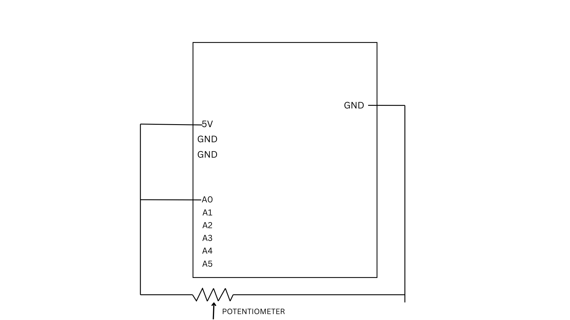
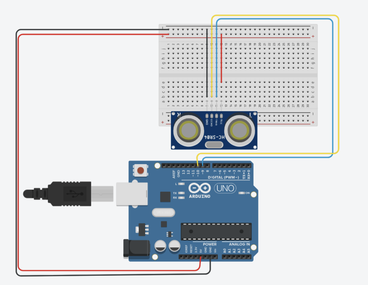
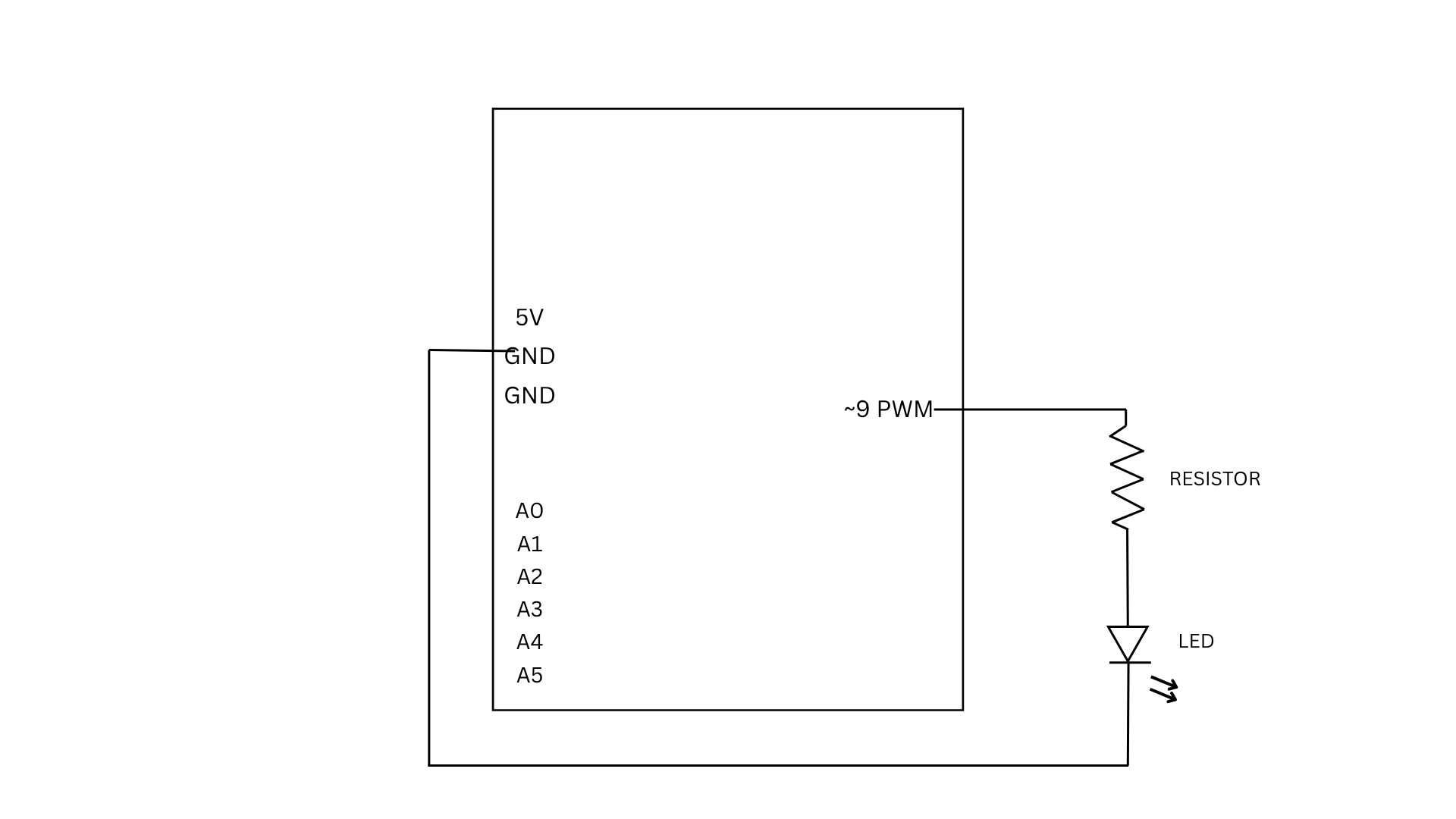
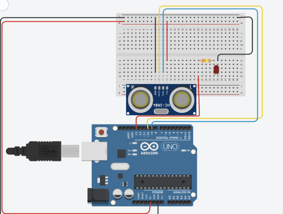
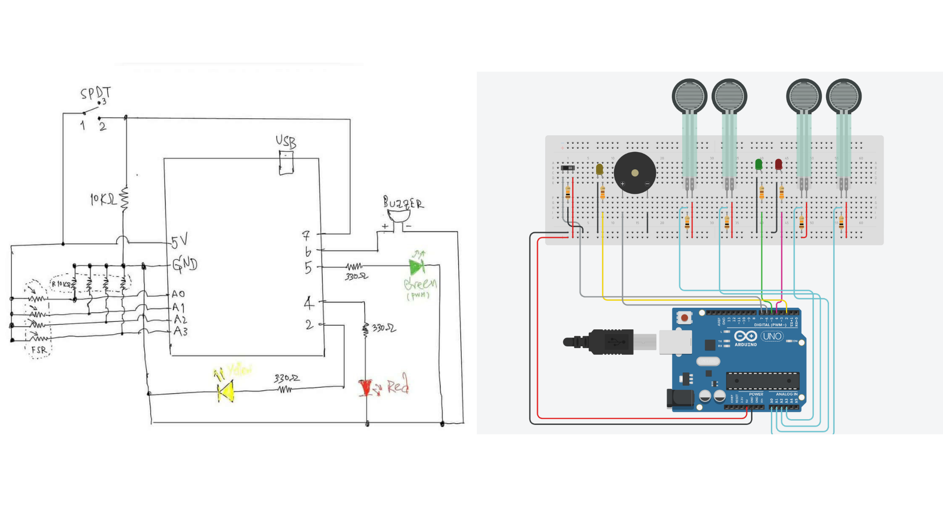
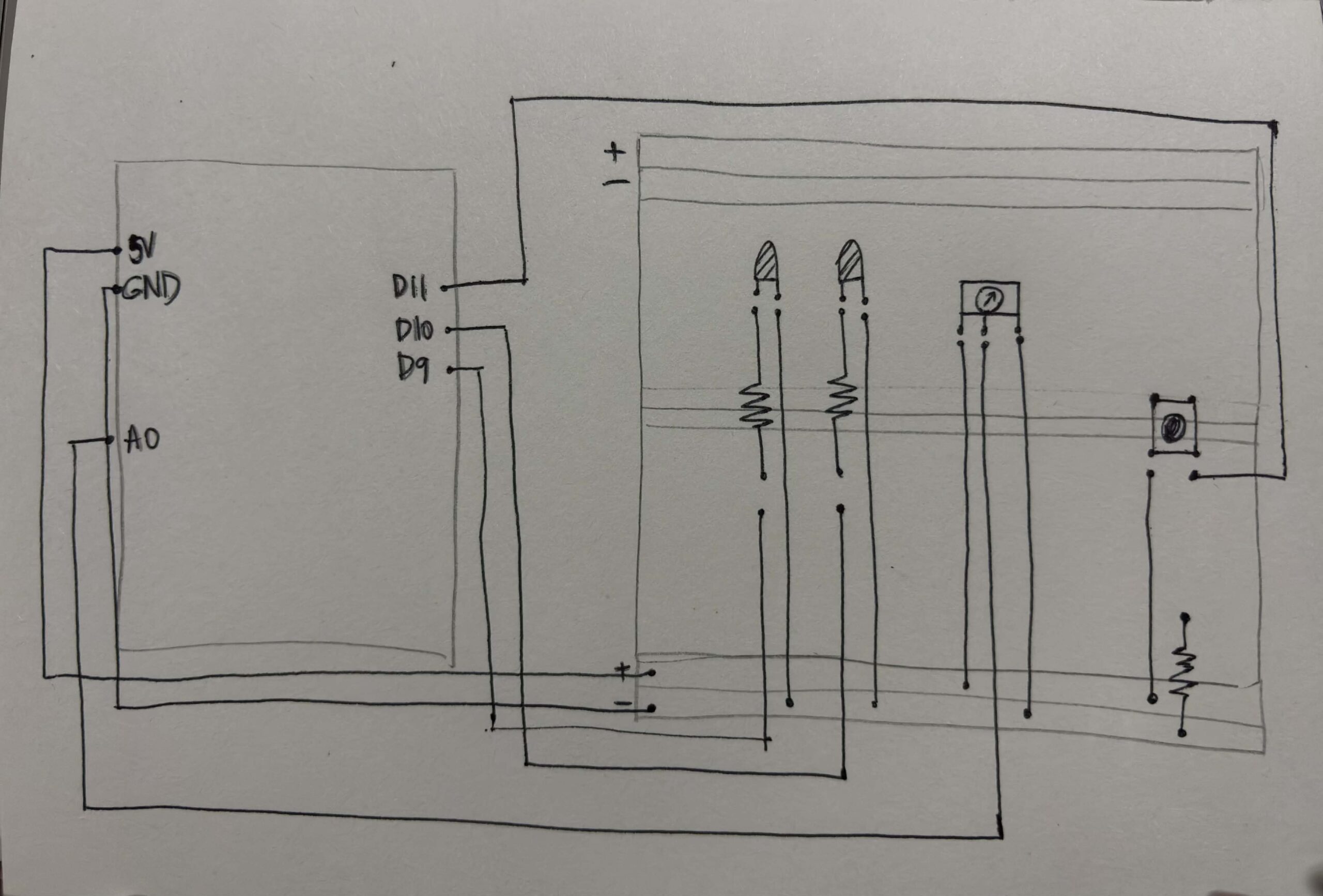
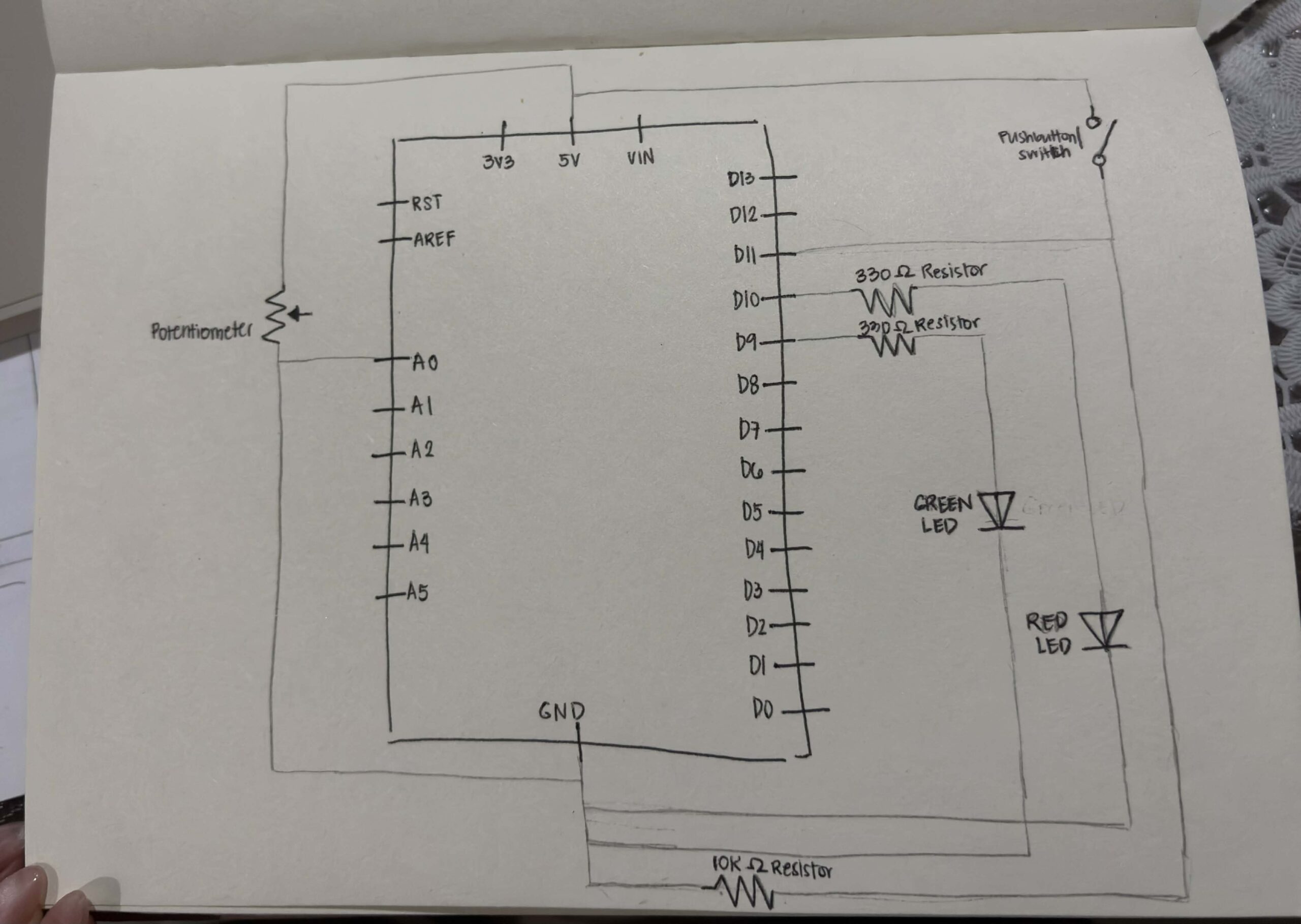
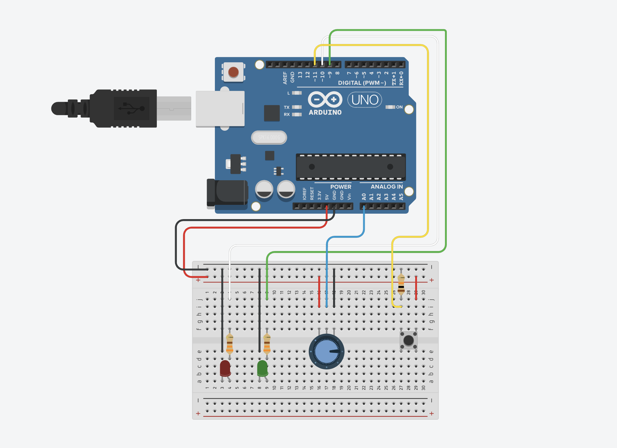
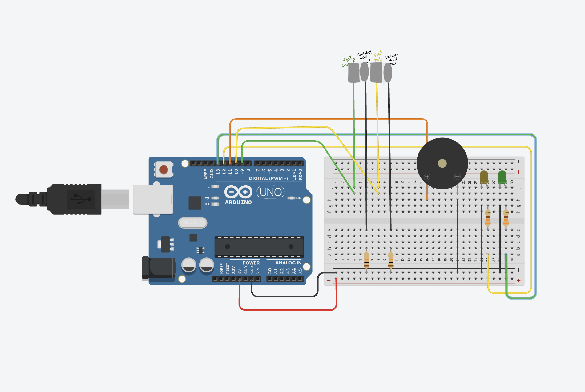
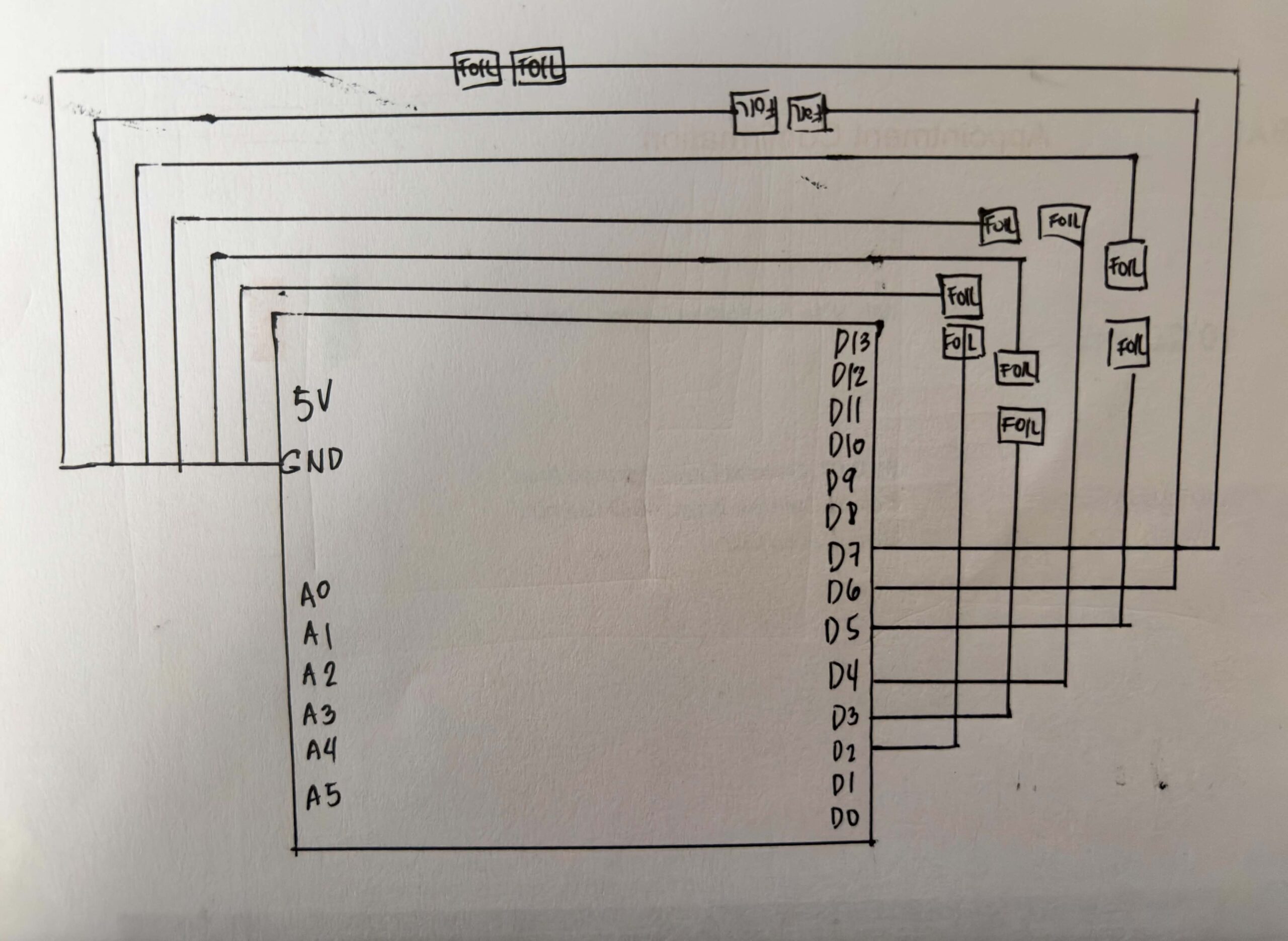
SCHEMATIC DRAWING:
USER TESTING:
HOW DOES IMPLEMENTATION WORK?
INTERACTION DESIGN – For the interaction design, I first wanted the game to show all the sequences continuously before the player could input them. However, while coding and testing it, I realized it was too difficult, especially because some tiles require multiple holding actions. Because of this, I divided the gameplay into a show phase and an input phase so players can first memorize the sequence, then perform it more clearly one step at a time. I also added countdowns and timers to guide the player and make the gameplay more challenging.
Aside from the spacebar for transitions, most of the interaction happens through the Arduino board, making the experience more physical and interactive. I also added background music and used brighter visuals because I wanted the game to feel lighter and less like a typical arcade game.
ARDUINO | GITHUB
The Arduino code that I used for this project is really straightforward. The code snippet below shows that the Arduino continuously reads each sensor. When a sensor changes from unpressed to pressed, or from HIGH to LOW, it sends the sensor number to p5.js through serial communication.
for (int i = 0; i < 6; i++) { // loops and checks all 6 sensors one by one
   int current = digitalRead(sensors[i]); //checks if sensor is being pressed.
P5 & Code Highlight
The line of code that I was really invested in was this:
this.sequenceIDs = this.sequence.map(img => this.photos.indexOf(img));
I got help from ChatGPT with this code, and it really interested me because it showed me how the game could turn an image into a number that matched my sensors. It helped me understand that the program does not actually recognize the images themselves. Instead, this line turns each image into a number based on its position in the array, and that number is connected to a sensor on the board. This made me realize that behind the visuals, the game is really just comparing numbers between the screen and the Arduino input.
COMMUNICATION BETWEEN P5 AND ARDUINO
While the Arduino handles the physical interaction of the game, P5.js handles the game logic and visuals. The Arduino continuously reads the DIY Foil sensors on the Echo Move board to detect when the player steps or presses on something. Once an input is detected, Arduino sends the data to p5.js through serial communication in real time. When the data reaches P5, it handles the game logic and visuals. It shows the sequence the player needs to remember, reads the inputs coming from Arduino, and checks if the player followed the correct order and actions. Based on the player’s performance, p5.js decides if the player wins or loses and updates the game state on screen, and then sends it back to Arduino, which makes the arduino print it from the serial monitor.
ASPECTS OF THE PROJECT THAT I’M PARTICULARLY PROUD OF
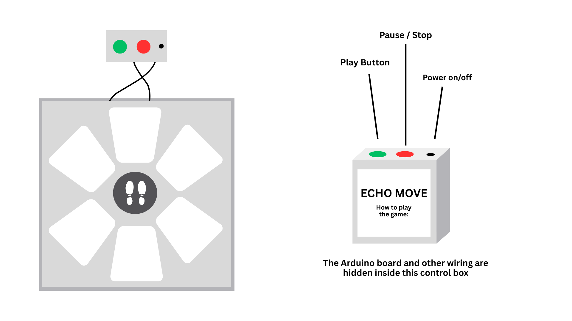
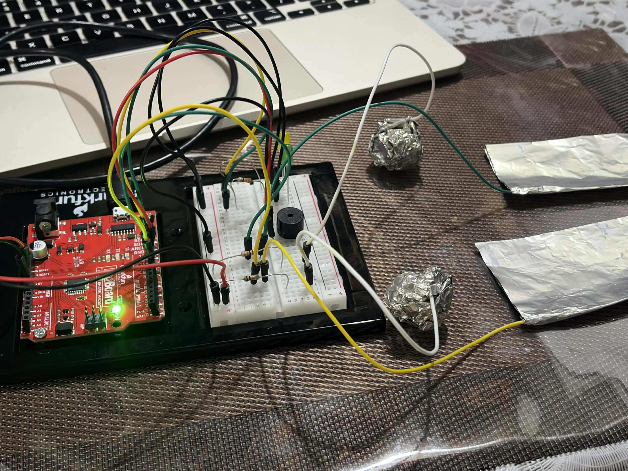
One aspect of the project that I’m particularly proud of is building the circuit and the board itself. As someone who enjoys crafting and making things by hand, I really liked the process of physically putting everything together and planning the wiring underneath the board carefully. I also used my unusual switch setup from my previous assignment, where I used DIY foil sensors and foil as part of the base wiring. Even though I ran into some problems during the process, I’m still really happy with how it turned out. I’m also proud that I didn’t follow a tutorial for the wiring setup and instead figured out most of it on my own.
CHALLENGES FACED
Most of the challenges I faced were during the coding process, and it was the part that took me the longest to finish. Since I couldn’t find tutorials that matched exactly what I wanted to make, I had to combine different references from the p5.js library, past class slides, Arduino cheat sheets, and other online resources.
One of the hardest parts for me was assigning different rules for each color. Originally, I also had a black tile whose rule was to be ignored, but for some reason, it kept causing problems in the gameplay logic. I spent a lot of time trying to fix it, researching solutions, and asking ChatGPT for help, but it still was not working properly. To focus more on the parts of the project that needed more attention and to manage my time better, I decided to remove it from the final version instead.
AREAS FOR FUTURE IMPROVEMENTS
I would like to add more levels and make the sequences more complex. If I had more time, I would also create more animations directly in p5.js instead of designing some visual elements in Canva and loading them as images. This would make the game feel more dynamic and interactive.
SOURCES
https://p5js.org/reference/p5/millis/ , https://editor.p5js.org/enickles/sketches/MBgdwrdPB
https://github.com/liffiton/Arduino-Cheat-Sheet/blob/master/Arduino%20Cheat%20Sheet.svg
.https://www.youtube.com/results?search_query=p5js+memory+game+tutorial
past class slides & previous assignments
USE OF AI
AI tools such as ChatGPT and Claude were mainly used to help me debug and understand my code throughout the project. They helped me figure out why some parts of my code were crashing, locate missing mistakes like semicolons or misspelled words, and understand why some of the logic I wrote was not working the way I expected.
I also used AI to help me understand some code from past class slides and the p5.js library, especially when I was confused about why they did not fully match what I wanted to happen in my own project. In some cases, AI helped me figure out missing logic or missing lines of code that I overlooked while coding. Aside from debugging, I also used AI for cleaning and organizing parts of the code to make it easier for me to understand and manage.
These are some of the lines of code and sections where AI assistance was directly used:
this.playerInput = (this.phase === "input") ? playerInput : -1;
This line of code really helped me organize the flow of the game better. It made sure that the board only accepts inputs during the input phase, so players won’t accidentally trigger sensors while the sequence is still being shown. I realized this made the interaction feel much clearer and less confusing, especially during testing.
let expected = this.sequenceIDs[this.seqIndex]; // the tile the player is supposed to press at the moment.

     // Hold logic
     if (this.playerInput === expected) {
       this.correctPressed = true; //if the player presses the correct tile, next sequence

     }

     if (elapsed >= this.inputTime) { // wait untill 6s ends

       if (this.correctPressed) { //
         this.seqIndex++; // show next sequence tile

         if (this.seqIndex >= this.sequence.length) {
I also had difficulty figuring out how to properly check if the player was stepping on the correct tile in the right order. ChatGPT helped me structure the game logic by comparing the player’s current input with the expected tile from the sequence array. It also helped me understand how to track the player’s progress using seqIndex and how to move to the next sequence only when the correct tile was pressed within the time limit.