FINAL PROJECT – Photo Booth : Design your ID card

CONCEPT

As I mentioned before, for my final project I decided to create an engaging experience for anyone on our campus at NYUAD to design their new ID card. This is supposed to tackle two aims: 1) bring joy and fun to people who are using the program; 2) allow people to be creative and design a card that suits their character.

At the very beginning, during the development of the idea, one of my classmates mentioned that my idea reminded them of a photo booth. This became the main concept of the experience. I constructed a real photo booth, to which people can come, sit down and take their selfies, as they like. If they do not like the picture, they can take it again as many times as they want, until they are satisfied with the result. So, this project would address the issue of dissatisfaction with ID card photos through the feature of capturing their images in real-time.

Then, participants can write whatever name they want on their new ID card. Sometimes people do not like the name that appears on their passport, which unfortunately they cannot change. However, in this project, I am giving them this opportunity.

Then, the fun part begins. Users can choose from a variety of images to be displayed on their ID. I have two categories: ANIMALS and HATS. They can choose whatever image they want by pressing buttons. Moreover, they can position them anywhere on their ID badge. This aims to enhance the individuality of their IDs.

Finally, they can save an image of their ID, which I will, of course, send to them afterward. So, this project seeks to not only address practical concerns but also provide a unique and enjoyable experience for users.

IMPLEMENTATION
Interaction Design 

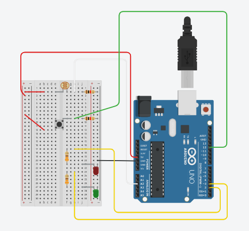
This is a P5 setup in the beginning:

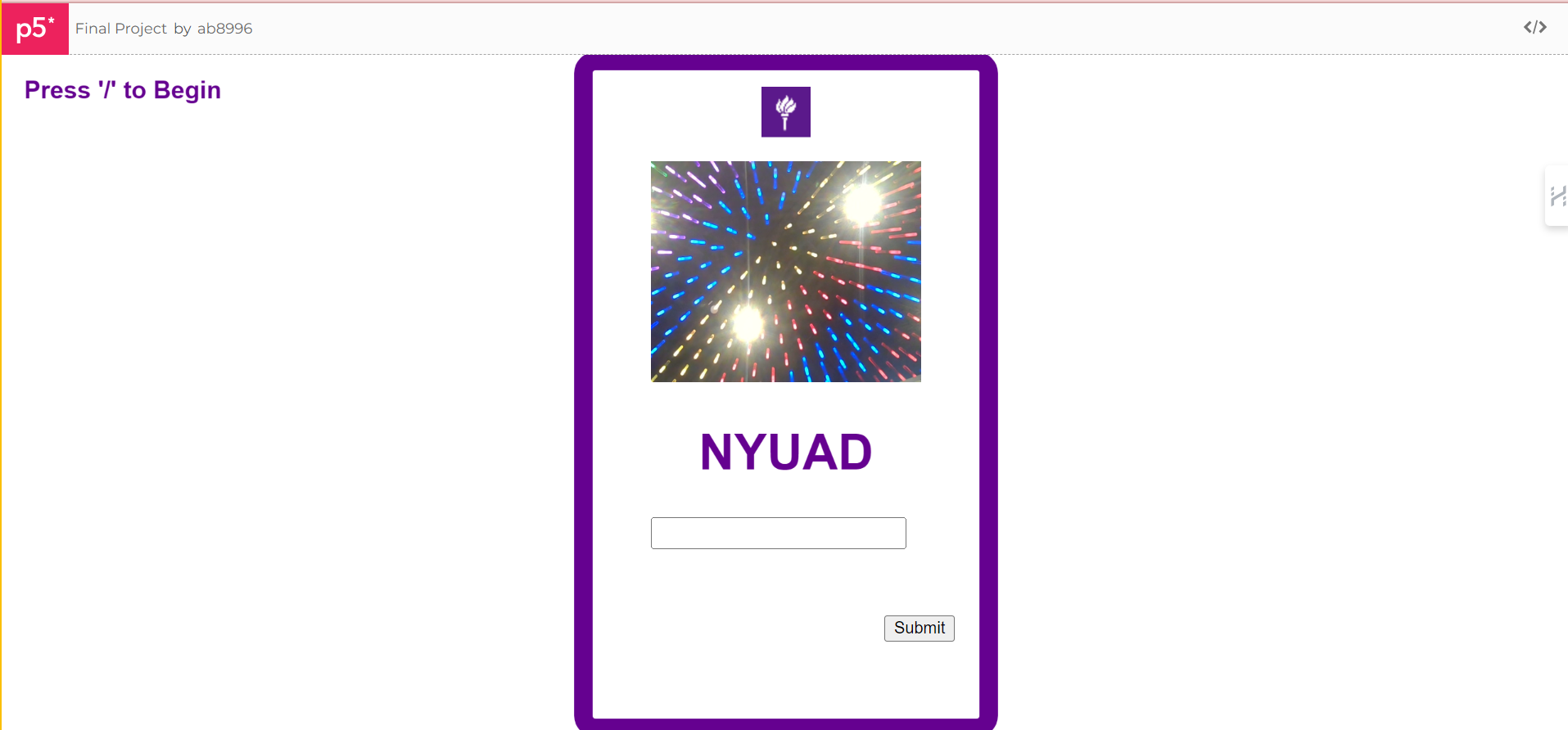
After you connect to the port by pressing the “/” key, and you press ENTER to take a snapshot, two images appear (animal and hat images).

You can go through an array of images by pressing the red buttons and choosing the hat and animal that you like. Further, you can adjust their position with potentiometer knobs. You can write your name in the input text box and SUBMIT it by clicking the button, so it appears as usual text on the ID badge. Finally, if you are satisfied with everything, you can click the CAPTURE button and save the ID badge.

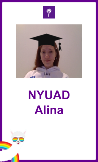
The final ID badge image looks like this:

Set up during the show:

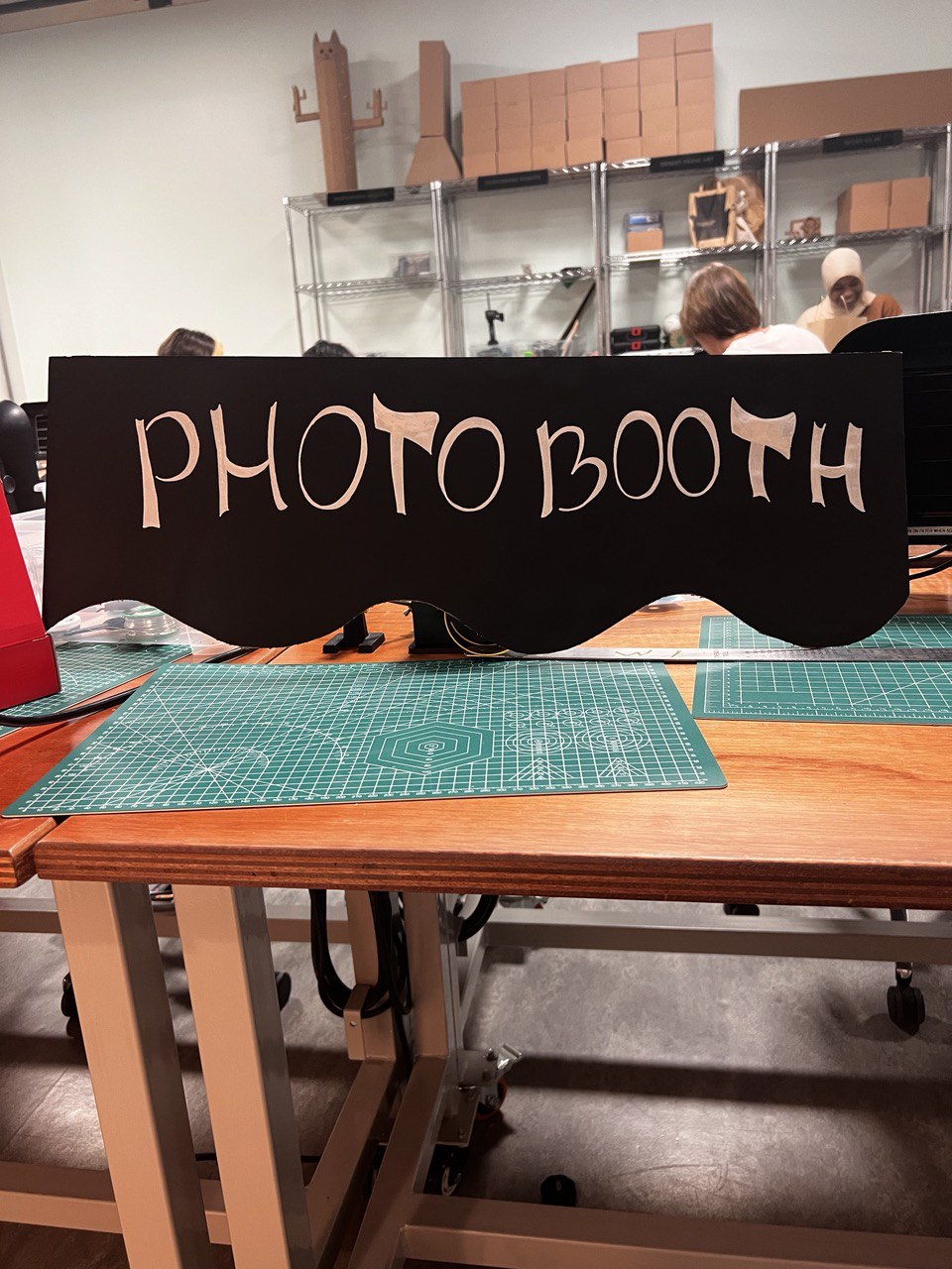
I have developed my concept further and designed a photobooth from cardboard. I printed out instructions and the table for people to fill in (where they would write their name and net ID, so I can send them the image of the ID badge later). I have designed this box from large cardboard pieces that I found in the lab. Painted the front with black acrylic paint and printed a design that reminds me of the film. 
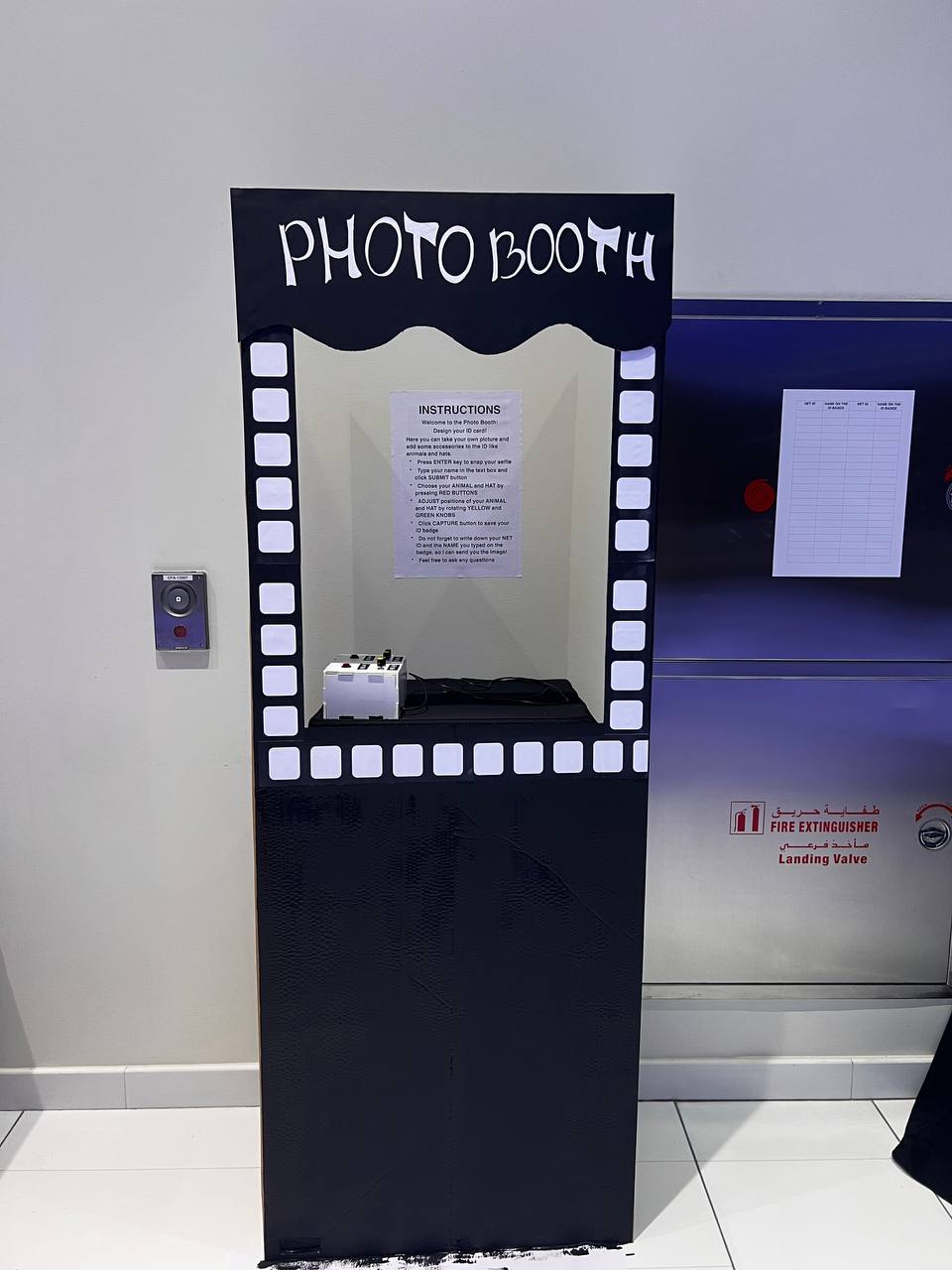
Process:

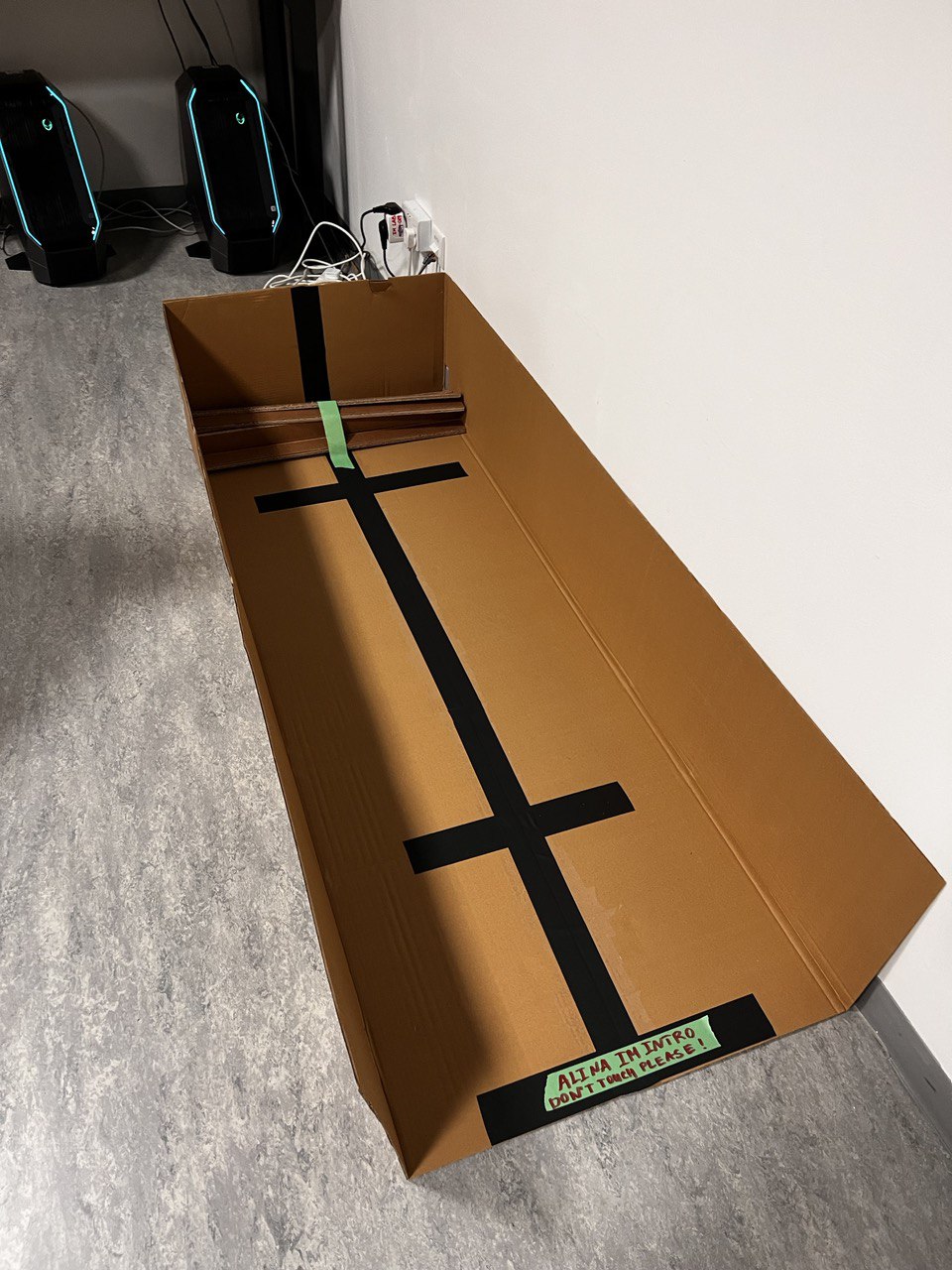
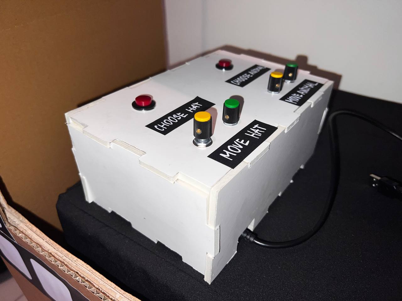
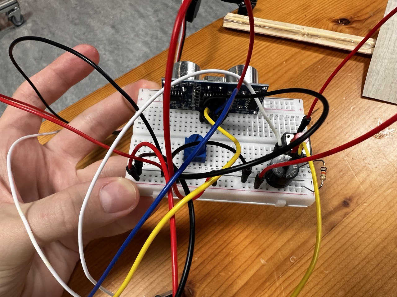
Another part of my project is a small white box that I built from foamboard, which holds two red buttons, 4 potentiometer knobs (yellow for the X axis and green for the Y axis), and labels for them. I have designed this box in the Maker Case.  Then I used a ruler and box cutter to cut all the parts and assemble them. They fit nicely, but I additionally used some glue to be sure the box can hold the pressure from pressing buttons and rotating knobs. 
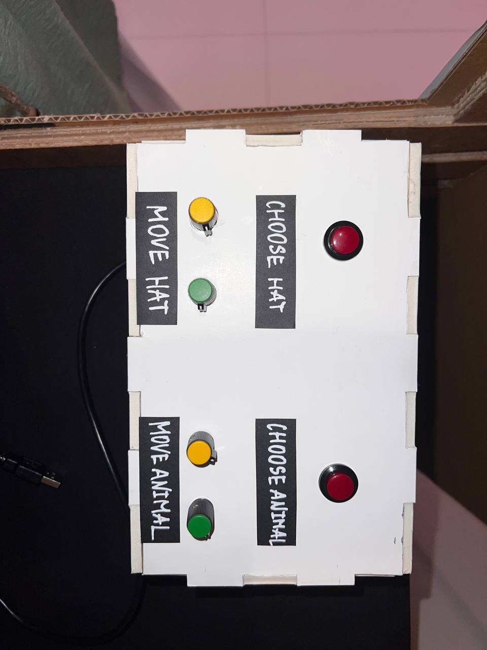
Process:

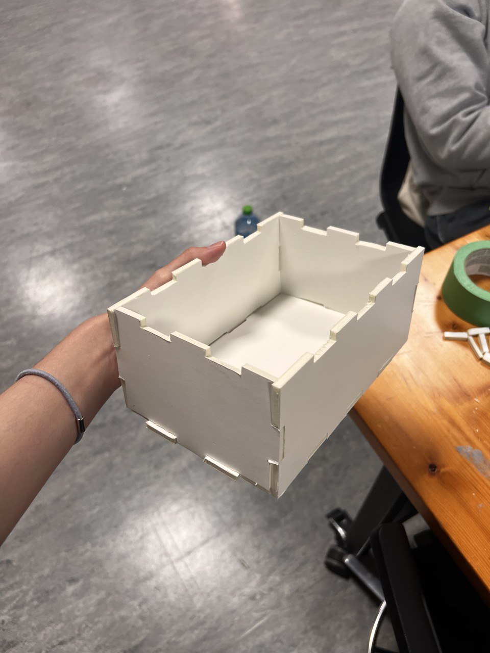
During the process of building these parts, the biggest challenge was cutting the elements. I did not have an opportunity to use a laser cutter, therefore I spent lots of time cutting and taping everything by hand.

P5 code

Most of the time was spent setting up the P5 sketch. What does it do? The P5 program starts with a display of an ID badge. I design these with primitive rectangular shapes and text. I wanted to include instructions on the screen. however, I did not want to overcomplicate the appearance of the sketch, so I decided to do it on an A3 paper. However, as I noticed not many were reading instructions presented behind the laptop, therefore, it would be better to present them on the screen.

On the P5, participants were presented with a live video which is the size of a snapshot they are about to make. As they press ENTER, the snapshot selfie replaces the live video. This was a very challenging part of the code. However, with some help, I was able to do this. Here is the portion of the code that I used as an example:

let capture;

function setup() {
  createCanvas(500, 500);
  capture = createCapture(VIDEO);
  capture.hide();
}

function draw() {
  let aspectRatio = capture.height/capture.width;
  
  image(capture, 0, 0, width, width * aspectRatio);
  filter(INVERT);
}

As soon as the photograph is taken, and if it is taken,  the signal to Arduino is sent, so it can now send communication to P5. P5 then acts as a receiver and displays different images of hats and animals. Moreover, participants can type their name in the input box and submit it to be displayed on the screen. Finally, by clicking capture they can save their ID cards. This is all done with built-in boxes and buttons in P5.

It was hard to figure out the logic that I wanted my program to have. But finally, I managed to do a set of nested if statements which I am very proud of. This is a part of the code that allows you to go in an array of images and select their position.

 if (snapshot) {
    // Display a captured selfie in place of the live video
    // resizing to the same parameters as video

    image(snapshot, width / 2, height / 2 - 100, 220, 180);

    // A nested if statement:
    // if -1 then no hat image is selected, otherwise the statement is true.
    // If a hat image is selected, then display the image at the index selectedHat from the array of hatImages.
    // The image is placed at coordinates (hatX, hatY).

    if (selectedHat !== -1) {
      image(hatImages[selectedHat], hatX, hatY);
    }

    // A nested if statement:
    // if -1 then no animal image is selected, otherwise the statement is true.
    // If an animal image is selected, then display the image at the index selectedAnimal from the array of animalImages.
    // The image is placed at coordinates (animalX, animalY).

    if (selectedAnimal !== -1) {
      image(animalImages[selectedAnimal], animalX, animalY);
    }
  }
}
Final Code for P5- embedded sketch: 
Arduino Code

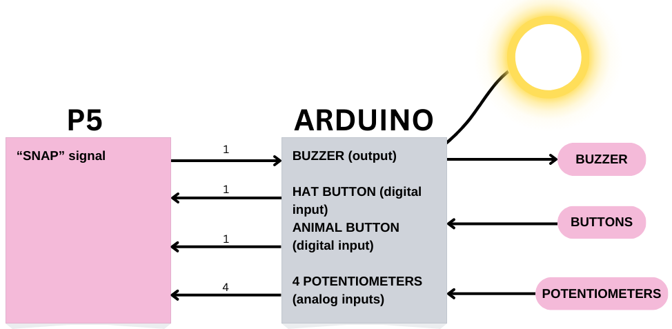
Setting up the Arduino code was pretty easy. I used only the information we learned in class.   The code consists of the declaration of 2 buttons, 4 potentiometers, and their states. The state of each button and the potentiometer is read and sent to p5.  The part that I am proud of is mapping the potentiometer values to the desired range of the canvas. This was a very important part of the Arduino code because, with this, users were able to adjust the position of hat and animal images.

  • When pressing the HAT button, which is a digital input on pin 2, participants will see an image of a hat. They can choose their hat by pressing the button again.
  • Then participants will need to adjust the position of a hat using 2 potentiometers that also operate on 2 potentiometers, which are analog inputs and located on pins A0 and A1.
  • They can also do the same actions to choose their favorite animal by pressing the ANIMAL button. They can also select an appropriate location using two potentiometers, which are analog inputs and located on pins A2 and A3.
Final code for Arduino: 
const int buttonHatPin = 2;        // Pin for the hat button
const int buttonAnimalPin = 3;     // Pin for the animal button
const int potentiometerHatXPin = A0;  // Pin for the X-axis potentiometer for hat
const int potentiometerHatYPin = A1;  // Pin for the Y-axis potentiometer for hat
const int potentiometerAnimalXPin = A2;  // Pin for the X-axis potentiometer for animal
const int potentiometerAnimalYPin = A3;  // Pin for the Y-axis potentiometer for animal

int buttonHatState = 0;       // Current state of the hat button
int buttonAnimalState = 0;    // Current state of the animal button
int potentiometerHatXValue = 0;  // Current value of the X-axis potentiometer hat
int potentiometerHatYValue = 0;  // Current value of the Y-axis potentiometer hat
int potentiometerAnimalXValue = 0;  // Current value of the X-axis potentiometer animal

int potentiometerAnimalYValue = 0;  // Current value of the Y-axis potentiometer animal

void setup() {
  Serial.begin(9600);               // Initialize the serial communication
  pinMode(buttonHatPin, INPUT);     // Setting up the button pin as input
  pinMode(buttonAnimalPin, INPUT);  // Setting up the button pin as input


  // START THE HANDSHAKE TO SEND 6 VALUES FROM ARDUINO TO P5
  while (Serial.available() <= 0) {
    digitalWrite(LED_BUILTIN, HIGH);  // on/blink while waiting for serial data
    Serial.println("0,0,0,0,0,0");    // send a starting message
    delay(300);                       // wait 1/3 second
    digitalWrite(LED_BUILTIN, LOW);
    delay(50);
  }
}

void loop() {
  buttonHatState = digitalRead(buttonHatPin);           // Read the state of the hat button
  buttonAnimalState = digitalRead(buttonAnimalPin);     // Read the state of the animal button
  potentiometerHatXValue = analogRead(potentiometerHatXPin);  // Read the value of the X-axis potentiometer for hat image
  potentiometerHatYValue = analogRead(potentiometerHatYPin);  // Read the value of the Y-axis potentiometer for hat image
  potentiometerAnimalXValue = analogRead(potentiometerAnimalXPin);  // Read the value of the X-axis potentiometer for animal image
  potentiometerAnimalYValue = analogRead(potentiometerAnimalYPin);  // Read the value of the Y-axis potentiometer for animal image


  // Map the potentiometer values to the desired range
  int hatX = map(potentiometerHatXValue, 0, 1023, 0, 900);  // Map X-axis potentiometer value to the canvas width
  int hatY = map(potentiometerHatYValue, 0, 1023, 0, 900);  // Map Y-axis potentiometer value to the canvas height

  int animalX = map(potentiometerAnimalXValue, 0, 1023, 0, 900);  // Map X-axis potentiometer value to the canvas width
  int animalY = map(potentiometerAnimalYValue, 0, 1023, 0, 900);  // Map Y-axis potentiometer value to the canvas height

  // Send the button states and potentiometer values to p5.js
  Serial.print(buttonHatState);
  Serial.print(",");
  Serial.print(buttonAnimalState);
  Serial.print(",");
  Serial.print(hatX);
  Serial.print(",");
  Serial.print(hatY);
  Serial.print(",");
  Serial.print(animalX);
  Serial.print(",");
  Serial.println(animalY);

  delay(100);  // Delay for stability
}
Communication between Arduino and P5
The communication is one-sided in my project. I am sending all 6 signals from Arduino to P5 (2 buttons states as digital inputs and 4 potentiometers states as analog inputs). From P5 to Arduino it is an empty line communication which I ignore. Although I planned to have communication from P5 to Arduino as a sound buzzer that would remind me of a snapshot sound, due to time constraints I decided not to do it. This turned out to be the best decision because it was very loud during the showcase and other projects that had sounds were very hard to hear.
FUTURE IMPROVEMENTS AND REFLECTIONS
What are some aspects of the project that you’re particularly proud of?

Overall, I am very proud of the fact that I was able to do this project at all. Given the fact that I have never coded before, and I was not very successful in my midterm project, I am very happy that I was able to finish the final project and it was functioning nicely during the 2 hours of the IM showcase.

I am very proud of the fact that I now understand how to program and be able to use the knowledge that I learned in class to build my own program.
I am very proud that my project was successful and that I was able to make an interesting, engaging, and fun experience for all age categories that were present during the showcase. I believe that finalizing my concept by building a huge Photo Booth was the key as it attracted the attention of the users. They wanted to come closer and see what was going on. My users were professors, students, and even kids. They all enjoyed the cute hats and animal images that I chose and were happy that I would send them their ID cards.
What are some areas for future improvement?
I feel that this project that even be taken to the next level. Maybe installing such kind of a photobooth for everybody’s use on campus is a potential. Instead of saving a picture, I would make this a printable ID badge, just like in the bank office where they print bank cards.
If I would go back and redo some aspects, I would add lights that users can adjust and some kind of filters to enhance their photographs. I would probably use a usual camera, so the quality of the picture taken is much better.
Moreover, during the showcase, I was asked if it was possible to resize the image of a hat. Next time I would add a potentiometer to do this. Moreover, I would flip a camera, so it reminds me of an actual picture taken. Most girls found this to be problematic.
ACKNOWLEDGEMENT AND SOURCES
My professor Michael Shiloh helped me a lot during this process. I am grateful for his emotional support and for debugging the program with me at every step!
Thanks to Professor Aya for explaining to me how to resize and capture a video as an image!
And thanks to Professor Mang for identifying that my potentiometers were not functioning and for providing me with new ones!
I mainly used the P5 Reference page. It is very very helpful!
Links to images I used:
Animals:
Hats:

Final Project: User Testing

USER TESTING – TRIAL 1

I asked my friend to try out my program without giving any direction of what the person should do. To my surprise, they did not struggle at all and found this experience to be very engaging and fun. They were able to figure almost everything out on their own. The only prompt I would give them is that ENTER key should be pressed to take the picture first. The manipulations of hat and animal images were fairly easy, as well as inputting their own name and pressing SUBMIT button. Finally as they were happy with the result they figured out to press the CAPTURE button to save an image. I feel that the confusion with the ENTER button happened because I do not state it anywhere on the screen nor on a paper. Therefore, I decided to incorporate this detail in the code. Moreover, one major feedback I received from my friend was to allow people to take a new selfie if they wanted to. Therefore, I decided to make a reset function, so that a person engaging with my project might change their selfie if they do not like it.

USER TESTING – TRIAL 2

After building my box, and making the reset function, I decided to test my project again. Although I had specifically stated that the person should press / to begin on the screen, they did not understand it in the beginning as their attention was captured by the CAMERA image. Moreover, as I did not have any labels on the box, they were not able to identify which button and potentiometer stand for what during their first trial. Therefore, I decided to put labels on my box under each button and two potentiometers. However, as I told them that they can press a button to reset, they figured out how to use controls on their own.

Also, I would just lead them anytime I saw they were a little bit stuck. I do not think it is an issue with labels,  because all the buttons are clearly labeled in p5. I think it is a matter of understanding the whole process, for which I will have additional instructions.  Moreover, I will press / to connect the serial port myself, so participants would not need to worry about this text appearing on the screen. They would see no text when the port is connected.

IMG_5377
IMPROVEMENTS

1) I will print out the instructions for the users, so that they could first read them and then engage with the project. They could also look for the additional instructions during their engagement with the project, so that I do not need to explain it several times.

2) In general, after some time, two of my participants in the user trials were able to understand how the controls work. Nevertheless, they need some time to figure out what each control does. Therefore, adding  labels to my buttons and potentiometers would help eliminate this problem.

3) Because people do not get to see their final badge of the ID and it saves directly to my laptop, I decided to have a table where participants can write their net id and the name on the badge. So, after the IM showcase, I would be able to go back and send all of the badges to the users.

4) During the second user trial, the user mentioned that they did not want the hat, so they placed it directly on the animal. This was an interesting observation, however not all hats would suit an animal. Therefore, I decided to have more animals and more hats to choose from. As my program is working fine now, I feel that participants would find my project more engaging with a bigger choice of hats and animal images.

5) Also, I wanted to incorporate other images like sunglasses or jewelry, however, as I was doing trials, I understood that people take photographs from different distances from the camera. Someone would take a picture pretty close and some would take it far away. Therefore, I decided not to incorporate these features. Moreover, I was suggested to have an additional potentiometer to control the size of an image, which could resolve the problem I stated above, however, due to time limits I was not able to incorporate this feature. This could become a future improvement for this project.

Week 12 – Final Project Proposal

Concept

For my final project, I aim to create an engaging and personalized experience that will allow our students and workers to design their own NYUAD ID cards.

This project would address the issue of dissatisfaction with ID card photos. Individuals will be able to take their own photographs, through the feature of capturing their images in real-time.

Additionally, recognizing the importance of chosen names, I intend to include a space for users to input their preferred names, which will then appear on their ID cards.

To enhance individuality, the program will offer options to customize the photos with accessories like hats. People will also be able to choose their preferred animal to be displayed in the corner of the ID card.

This project seeks to not only address practical concerns but also provide a unique and enjoyable experience for users.

Design of the ID card (3 options) :
Production


  • P5 program will start with a display of a menu where people can read instructions and click “space” key to start the experience.
  • They will be presented with a live video so that participants can adjust their position and click enter to capture their selfie- photograph.
  • As soon as the photograph is captured the signal to Arduino is sent, so it can activate the buzzer. Arduino receives this as an output from the buzzer and activates a short sound that reminds one of the camera’s shot.
  • On the P5 sketch, the live video stops playing and participants are presented with the photograph.
  • Then participants can select their accessories as additional features for their ID card. This is done by sending communication from Arduino to P5(receiver).
  • When pressing the HAT button, which is a digital input on pin 2, participants will see an image of a hat. They can choose their hat by pressing the button again.
  • Then participants will need to adjust the position of a hat using 2 potentiometers or a joystick that also operates on 2 potentiometers (which are analog inputs and located on pins A0 and A1).
  • They can also do the same actions to choose their favorite animal by pressing the ANIMAL button. They can also select an appropriate location using a joystick or two potentiometers.
  • Participants will press ENTER to capture the new image with the chosen hat and animal, which then will be displayed on an ID card template on a P5 sketch.
  • Finally, participants can write their names on the ID card by inputting it in a given space.
  • By clicking the button “Finish” their final ID card will be printed and displayed as a small image on top of the menu screen.


Serial Communication: In-class exercises

EXERCISE 1

Task: make something that uses only one sensor on Arduino and makes the ellipse in p5 move on the horizontal axis, in the middle of the screen, and nothing on arduino is controlled by p5

Code for P5 and Arduino commented at the end of it:

Demonstration: 

EXERCISE 2

Task: make something that controls the LED brightness from p5

Code for P5 and Arduino commented at the end of it:

Demonstration:

EXERCISE 3

Task: take the gravity wind example and make it so every time the ball bounces one led lights up and then turns off, and you can control the wind from one analog sensor.

This was the hardest exercise to do. I made it work, however, instead of fully turning off when the ball is fully on the ground, the LED lights up. This would be a problem to solve in the future.

Code for P5 and Arduino commented at the end of it:

Demonstration:

Final Project – Preliminary Concept

For the final project, I have decided to create an immersive experience where people could make their own NYUAD ID cards.

Usually, people do not like the photographs on their ID cards. This issue inspired me to program a way in which we can take our own photos for the ID. For instance, a user can press a button and take their photo live by looking at the camera. Maybe I will also mirror the final photograph so that it looks just as when you look at yourself in the mirror. According to my research, people actually think that a mirror reflection is much more attractive to you than a photograph.

Moreover, I have some friends who chose or go by a different name than the one in the passport. This will also be incorporated in this program, where a person could write their preferred name on a touch screen, which will be reflected on their ID.

Also, I believe that many students can relate to the issue that our ID cards are not unique and do not show any individuality. In my program, there will be an option to add accessories to their photos. For instance, I plan to incorporate different images of scarves, jewelry, hats, mustaches, etc.

NYU New York has already made some changes to their ID cards, where students can change their ID cards for free.

New York University on X: "NYU community members who would like to: • have  their NYU ID card replaced to reflect their chosen/preferred name, or •  have the photo on their card

Furthermore, as suggested by my classmates and Professor Shiloh during the class discussion, I can add an option to control lighting using a ring light (brightness through a potentiometer and color of the light by linking the remote to Arduino). In this way, people can control the setting in which they take the photo, which is also very important to the quality of your final photograph.

The ID card will resemble the NYU ID, however, incorporating all the features mentioned above should produce a fun and engaging project.

Week #11 – Reading reflection

Design Meets Disability

I really liked the discussion on the tension between fashion and discretion. Specifically, Graham Pullin shows how glasses become not just an assistive medical device, but it transformed into a fashionable item of “our garderobe”. In my own experience, I have many friends who used to wear glasses without lenses or lenses without dioptri. I chose glasses according to my aesthetic tastes and only then I would think about their practicality and the medical parameters. These examples prove the point made by Pullin and point to the rightness of her arguments.

It is not the first time I have heard that disability is not solely a medical issue. Instead, it stands as a social and cultural one. In the field of disability studies, this is called a medical model.

The Medical Model views disability as resulting from an individual person’s physical or mental limitations, and is not connected to the social or geographical environments. The Medical Model focuses on finding a “cure” or making a person more “normal.”

© University of Oregon

Having taken a course in disability studies previously, this reading was not really eye-opening to me. However, I understand that the topic of discussion in this article is thought-provoking and relates to our class material a lot. Such question as to how we make designs more accessible is important. I believe we should try and pursue designs that are suitable for everyone. We, as designers, can make things accessible and take action towards building a  more inclusive society.

Self- playing dancing instrument

Concept

For this assignment, we decided to do a musical instrument that will produce music on its own. Typically, musical instruments are associated with a person playing them. However, in our project, we devised a system wherein a performer assumed the dual role of both playing the instrument and acting as the player. The servo motor symbolizes the player, while a piece of cardboard mounted on a stick symbolizes the instrument.

How music is produced:

As the servo motor moves, the attached pad also moves, causing variations in the distance detected by the ultrasonic sensor. Depending on these different distances, the speaker emits sounds with varying frequencies.

Setup

Video


Code and highlights of the procedure
  1. We have used the example in the kit’s documentation (you can find it here) to code the distance sensor, adjusting some aspects of it.
  2. We manipulated the position of the servo motor by using myservo.write() and delay(). Here, we played with degrees and set up the delay to be 50ms for the servo to reach the position.
  3. We used the function of a map() and constrain() together, as learned in class, to match the distance values to the frequency values.
  4. We also added a button, which when pressed can change the frequency range, so that all the melody’s frequencies are higher.
// assign the variables for distance and button
#define trigPin 13
#define echoPin 12
#define buttonPin 2

// include library for Servo motor
#include <Servo.h>

Servo myservo;  // create servo object to control a servo
// twelve servo objects can be created on most boards

// assign the first position
// variable to store the servo position
int pos = 0;


void setup() {
  Serial.begin(9600);
  pinMode(trigPin, OUTPUT);  //distance
  pinMode(echoPin, INPUT);
  myservo.attach(9);  // attaches the servo on pin 9 to the servo object

  pinMode(buttonPin, INPUT);  // switch
}

int frequency;  // assign the frequency variable

void loop() {
  // from distance sensor example
  long duration, distance;
  digitalWrite(trigPin, LOW);  // Added this line
  delayMicroseconds(2);        // Added this line
  digitalWrite(trigPin, HIGH);
  //  delayMicroseconds(1000); - Removed this line
  delayMicroseconds(10);  // Added this line
  digitalWrite(trigPin, LOW);
  duration = pulseIn(echoPin, HIGH);
  distance = (duration / 2) / 29.1;


  if (distance >= 200 || distance <= 0) {
    Serial.println("Out of range");
  } else {
    Serial.print(distance);
    Serial.println(" cm");
  }


  // we contrain the distance to be from 0 to 50 and map the distance values to the frequency values
  // if the button is not pushed then the melody plays in low frequencies
  // if the button is pushed, then the frequency  is higher


  if (digitalRead(buttonPin) == LOW) {
    frequency = map(constrain(distance, 0, 50), 0, 50, 100, 1000);
  } else {
    frequency = map(constrain(distance, 0, 50), 0, 50, 500, 2000);
  }

  //code for SERVO position
  myservo.write(90);
  delay(50);
  myservo.write(45);
  delay(50);
  myservo.write(25);
  delay(50);
  myservo.write(70);
  delay(50);
  myservo.write(100);
  delay(50);
  myservo.write(60);
  delay(50);  // waits 50ms for the servo to reach the position

  // play the sound from pin 6
  tone(6, frequency);
}
Reflection

We faced one issue when building the setup. We wanted to use a bigger servo motor which is stronger and could hold the stick, however, it was not working the way we planned (not like a mini one in our kit). As we researched, we found out that actually, this servo motor allows for full-speed rotation at the value of 180 and a stop at the value of 0. This was not suitable for our project, so we proceeded with using a hot glue gun to connect the stick to the servo motor we had in the kit.

We could also make the appearance better by decorating the cardboard using for example an image of a robot.

Moreover, for future projects, we could actually play different melodies and control the volume using the potentiometer. Otherwise, we could use a potentiometer to manipulate the movements of the servo motor, by coding different patterns of the moves produced by the servo motor.

Overall, I think this was a fun project to do and I liked the final result a lot!


Week 10- Reading reflections

A Brief Rant on the Future of Interaction Design

From a psychological perspective, the author’s critique makes total sense because it values the sensual experience over the aesthetical and fancy way of an interactive system. For instance, in the book I once read, O’Keane (2022) suggests that “one makes sense of the world through one’s senses and this becomes the basis for one’s interpretation of the world and for one’s memory.” There is actually one type of memory which is called haptic memory which is the form of sensory memory specific to touch stimuli. So, I believe the author’s argument is very clear and in touch with the specific research in psychology.

However, the article did not offer clear and specific solutions to what can we do as an alternative. I think the author could have provided some options that are available today and that focus somehow on the haptic aspect. For example, Humane™ just launched its much-awaited #hardware device, which has been purpose-built for the new AI era from the ground up: here is the video. It is more human-centered design in technology and it gives an option for manipulating the technology with our hands.

A follow-up article

I think that most of my own critiques and questions from the previous article were answered in this follow-up. I think that authors should respond to critique to engage with readers, gain valuable insights, improve their work, and build a supportive community. Responding to the critique fosters a connection, and enhances the collaborative nature of the creative process.

I genuinely believe that his ideas about giving up on our bodies are so important to talk about. This reminded me of a conversation that I had with my friend about what art is. Today, we tend to think that art is AI-generated images, temporary installations, etc. However, I think art is deteriorating as we rely less on hands-on craftsmanship like it was before for building sculptures and architecture (e.g. Acropolis of Athens). By embracing technology, we risk losing the tactile connection that brings authenticity and soul to artistic creations.

Week 9 – Pedestrian Problems

Concept

For this week’s assignment, I decided to show the common problem of pedestrians when crossing the road. My idea was to create a pedestrian crossing light, which would show the common problem of having “infinite” red light and only limited actual crossing green light. I believe this is a common problem in any country and anyone can relate to the idea of this project.

Video: Pedestrian Traffic Light

Diagram, Code, Highlights, and Challenges of the Project

To make this project, I decided to break it into three steps.

Firstly, I made a switch as a push button, which will turn on the green LED. For this, I built a circuit for the switch button, which I learned from the class material. I am proud of this step, as I could apply the previous knowledge (building the circuit of the light sensor) and understand how to do the same with the switch button. I used a 10K Ω resistor, a green push button (to indicate the same color as the LED color), a green wire that connects to pin 12, a red wire that connects to 5V, and a black wire for the GND connection. One challenge I faced was forgetting that the current could not jump from one place on the breadboard to another, so I added another red wire to finish the connection.

Moreover, I made a simple circuit for the green and red light, using green and red LEDs, 2 330Ω resistors, and yellow wires connected to pins 2 and 3. I didn’t have to use an additional black wire, as I intentionally had all of my components connected in a way that uses only 1 black wire connected to GND.

As I completed building this, I wrote a simple program that will turn on the green LED, and turn off the red LED, when the green button is pushed. Moreover, I made a code for the green LED blinking. For this part of the project, I used a digital sensor and controlled it in a digital fashion.

Lastly, I decided to add an analog sensor – a light sensor – which will control the brightness of the red LED. I had no problem building this part of the circuit, however, I had to decide whether I wanted to completely turn off the red LED or control the red LED in a fashion that is independent of the digital switch. If I decided to turn off the LED using a light sensor, I would need to think about 4 different options of its connection to the switch button: switch on & sensor value >400, switch on & sensor value <400, switch off & sensor value >400, switch off & sensor value <400. I decided that independent control of the light sensor would reflect my concept better. Therefore, I made a red LED to always have a dimmed brightness, and when the light sensor is covered the LED will become brighter.

Here, is the code for my program:

// assigning variables to the pins
// push button has a connection to pin 12
// green LED has a connection to pin 2
// red LED has a connection to pin 3

int pushButton = 12;
int greenLED = 2;
int redLED = 3;

// the setup routine
void setup() {
  // initialize serial communication at 9600 bits per second:
  Serial.begin(9600);
  // make the pushbutton's pin an input
  pinMode(pushButton, INPUT);
  // make green LED and red LED pins as output
  pinMode(greenLED, OUTPUT);
  pinMode(redLED, OUTPUT);
}

// the loop routine runs over and over again forever:
void loop() {

  // read the input pin of the push button:
  int buttonState = digitalRead(pushButton);
  // print out the state of the button:
  Serial.println(buttonState);
  delay(1);  // delay in between reads for stability

  // if statement for controlling the red and green LEDs through the push button (digital switch)
  // if button is pushed
  // turn off the red LED and blink the green LED with a delay in between the blinks

  if (buttonState == HIGH) {

    digitalWrite(redLED, LOW);

    digitalWrite(greenLED, HIGH);
    delay(1000);
    digitalWrite(greenLED, LOW);
    delay(1000);

    // if button is not pushed
    // green LED is always off
    // red LED is always on
    // and the red LED is controlled by the light sensor values a.k.a. the brightness
    // if the sensor value is less than or equals to 400, the brightness of the red LED is at maximum
    // if the sensor value is more than 400, the brightness of the red LED is alway dimmed at brighness of 10

  } else {
    //if the green button is not pushed,
    // the green LED is not turning on
    digitalWrite(greenLED, LOW);

    // initializing variable called sensorValue which reads the values from A2 analog pin
    int sensorValue = analogRead(A2);

    if (sensorValue <= 400) {
      analogWrite(redLED, 255);
    } else {
      analogWrite(redLED, 10);
    }
  }
}

Future Work and Reflection

Overall, I believe that I achieved all of my goals for this project. I was able to practice the knowledge I gained during class work and apply it in a new context. I am proud of the work I have done. Although I faced several challenges, which I described above, I was able to resolve them easily. For the next work, I am planning to keep up with my method of breaking the big project into smaller parts and achieving the same good results.


Week #9: Reading response

Physical Computing’s Greatest Hits (and Misses)

This article by Igoe was pretty easy to read with lots of examples that are very important for the students like us. I believe that I benefited from reading the text because it provides an overview of common themes in physical computing and offers inspiration for individuals interested in exploring this field. It encouraged me as a reader to think creatively about my own works. I especially liked how the author encourages his readers to have originality within common and recurring themes within the field of physical computing.

I think that there is no apparent bias in the article. The author presents the themes and examples objectively, providing a balanced view of each. It also makes me think about the origin of creativity, and how this concept should not be viewed as something that originates from a novel idea. In fact, even in sciences, it is common to have background literature for the “original” study, meaning that every idea is built upon preexisting ideas. Such an approach with a strong foundation is the best place for the development of new ideas.

Making Interactive Art: Set the Stage, Then Shut Up and Listen

I believe that the best thing about this article is that it encourages artists to think beyond traditional art forms and embrace interactive experiences. I really like how the author understands the importance of the spectatorship notion.  The emphasis on audience engagement and the value of the interpretations from the side of the spectator is definitely something that has been pursued in the field of contemporary performative art. I believe the very core of the spectatorship is the perception of the art piece by the viewer. It is not just about presence, but also it is about active recognition, understanding, and interpretation of the artwork. It of course doesn’t have to be verbalized in any way, it may even not make sense to the viewer, but the feeling that she/he/they would have was what matters.

From the perspective of students and designers, this article provides valuable insights into the approach and mindset required for designing interactive artwork, highlighting the importance of listening to feedback and adapting the artwork based on audience reaction. However, I believe that the author’s bias is towards creating interactive artwork that encourages audience participation and interpretation all the time, which is not an ideal thing to do because in that way such a working process may downplay the role of the artist’s intention. It may even create the potential for misinterpretation or lack of understanding from the audience, which is definitely not the intention of the artist.