
Generally, my testing went okay, though because I had not given instructions I think, though, my design was pretty intuitive in such. way I think they got what they were supposed to do. Because my project had to do with modulating sound, the feedback is pretty instantaneous, and because there was not objective, really, users could just mess around with what you can do and really quickly get the hang of it. I am still working on adding an instructions screen on p5, though. I think an easy instructions page would provide all the information people will need to do with my project, just explaining what the different controllers on my cat thing do to the sound.
Category: Fall 2022 – Mang
3 examples assignment – Aya&Nourhane
EXERCISE 1:
In this exercise, we used a potentiometer to control the movement of a circle in p5.
Here’s the video:
//ARDUINO CODE IS INSIDE THE SKETCH COMMENTED OUT AT THE END
ABOUT THE CODE:
The code allows to control circle on the screen using data received from the Arduino.
EXERCISE 2:
For this exercise, we are controlling the intensity of the LED using the UP, DOWN keyboard keys from a p5 sketch. We added cute clouds in the background and a sun. The LED is also yellow as if the sun is actually rising.
//ARDUINO CODE IS COMMENTED OUT IN THE SKETCH
ABOUT THE CODE:
The brightness of a sun-like circle in the center is controlled using the arrow keys. The sketch also establishes serial communication with Arduino to control the brightness of the LED.
EXERCISE 3:
In this exercise, we have two parts:
-First one is the bouncing of the soccer ball in the p5 sketch controls the ON/OFF state of the LED
-Second one is the ultrasonic sensor controls the position of the soccer ball in the soccer field.
PART 1: LED CONTROLLED BY GRAVITY
PART 2: BALL POSITION CONTROLLED BY ULTRASONIC
//ARDUINO IS COMMENTED OUT IN SKETCH
ABOUT THE CODE:
Final Project – Robotic Arm
For the final project, I wanted to make a robotic arm and a p5js sketch that would ask the user to stack blocks of different colors in the right order. As I started working on the project, I realized how difficult it was to make the robotic arm work.
I selected double layered popsicle sticks for the construction of the arm connected together by cardboard squares with slits in them. I wanted the arm to have 4 degrees of freedom. I used big servo motors for the base rotation and the 2nd degree of freedom. For the next two, I used small servos because the bigger ones were too heavy for the popsicle sticks to handle. Then, I went on to make the buttons for moving the arms which I needed 8 of, to account for each movement back and forth. The hardest part was to get the buttons working because there were so many wires and connections that there was always some variable not working properly. One thing that I didnt know at first was that I needed an external power source for the bigger batteries. So I got that working, but then what I didnt know after that was that I needed to ground the power source and the signal from the arduino both into the arduino. Being oblivious to this, I lost a lot of time. Finally, after getting buttons to work, I made the connections more permanent with screws, a lot of hot glue. I soldered the connections to the motors because the arm had to move and the jumper wires would fall out. There were 9 connections to solder for this.
Lazy Susan:
At the beginning the professor recommended me to use a lazy susan for the base rotation, and I constructed the whole thing with the lazy susan but it turned out to be less than ideal because the motor I was using wasn’t enough to turn the lazy susan, so that was a lot of time wasted as well.
Construction:
For the base I made a box out of cardboard and I used 8 big momentary switches as the controls. I had to solder all 8 momentary switches, which was 16 connections. I cut holes in the cardboard for the switches and left a huge opening so the base could rotate properly. I also layered several cardboard pieces around the base motor for more stability.
Progress Videos:
Final project progress
I have decided to scrap my previous ideas and instead, I am going to make a space game where users can control a spaceship on the screen using a steering wheel. I also want to implement laser shooting feature with a button. I want to implement some kind of communication from p5 to arduino as well but I’m not quite sure how I will do that.
Week 12 – Final Project Description
FINALIZED CONCEPT
I decided to stick with the idea of creating a Braille reader. The design of the device will be close to this, but I’m thinking about adding an additional hole for the light sensor, which will detect if the finger is placed on the device.
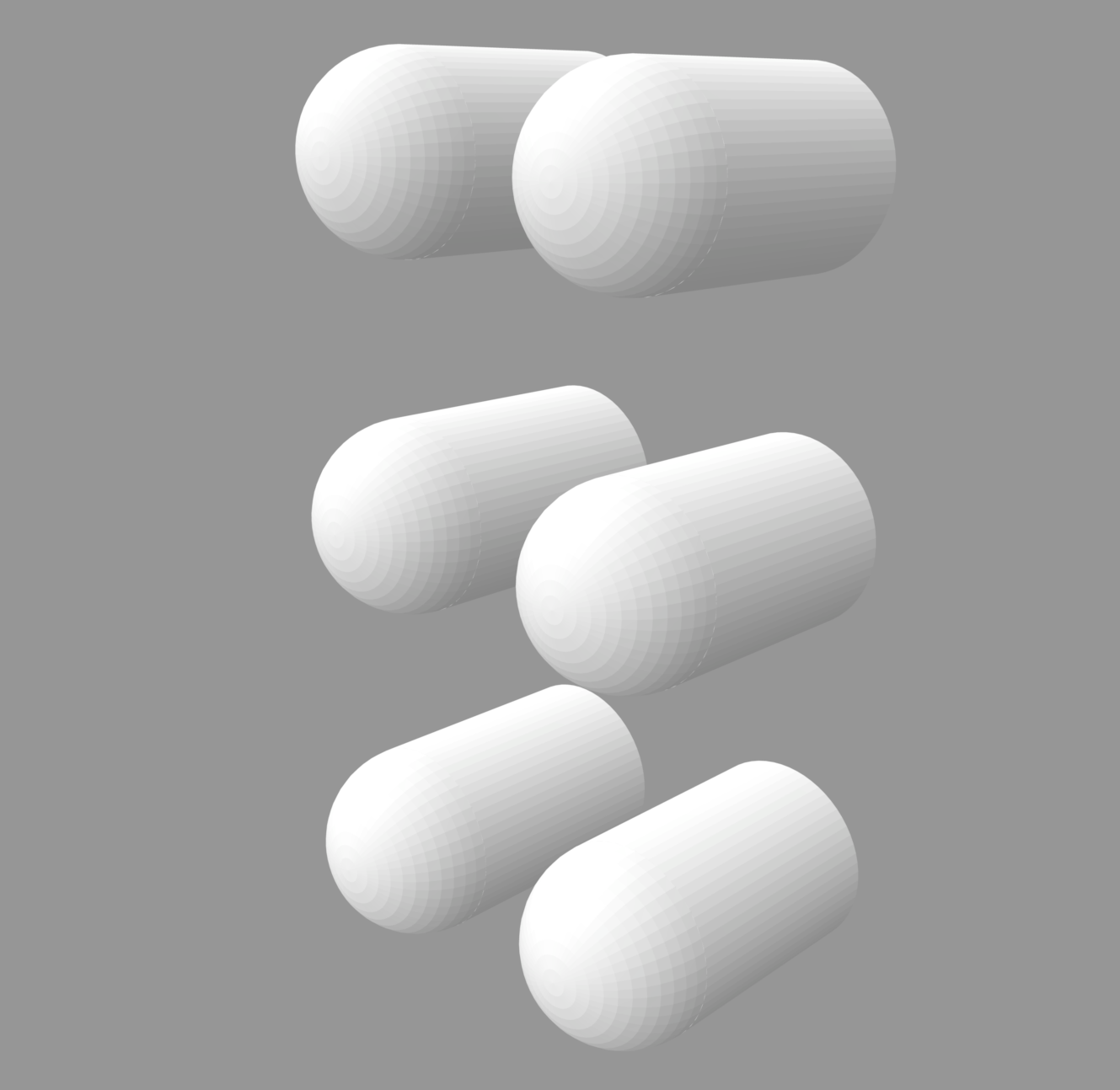
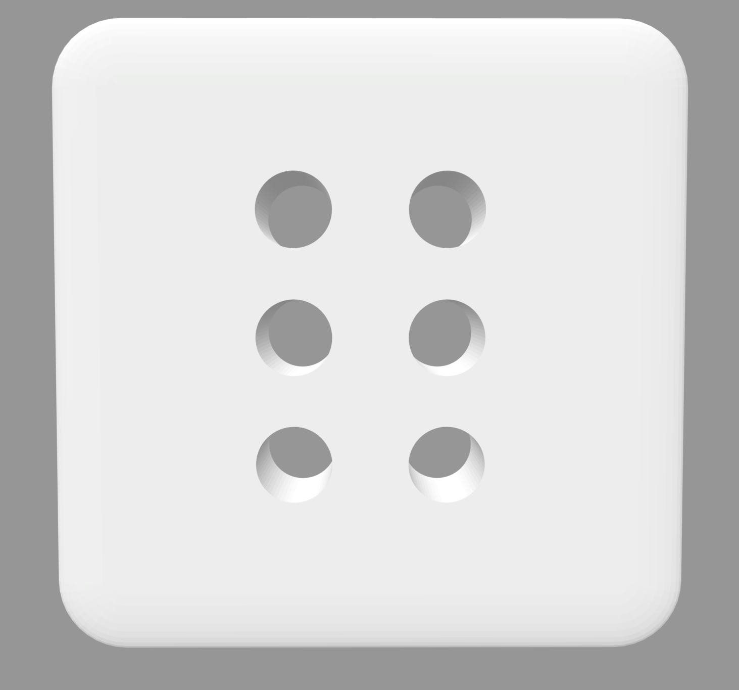
The platform will be the size of an index finger, allowing the user to use the device in limited spaces.
The solenoids will be used to put the parts into motion and will be controlled by the Arduino program, which will control their state. As my device is designed for people with sight problems, I will use the P5 only for the audio functions, allowing a person to get familiar with the functionality of the device on their own.
I will provide the user with two modes, controlled by the switches: reading mode and alphabet mode. Moreover, there will be one additional switch allowing the user to stop the program completely. In the reading mode, the device will work according to the texts downloaded into P5, while the alphabet mode will teach a person the alphabet while providing a sound accompaniment to the program.
The P5 sketch will receive information about the state of the switches, and if the Alphabet mode is activated, it will start receiving information from the Arduino about the state of the solenoids and, according to that, sounding out the corresponding letters.
Disability Meets Design
Reflecting on the insights I gained from this reading, it is evident that achieving the right balance in designing for individuals with disabilities is crucial. Leckey’s approach to creating visually appealing furniture for kids with disabilities, without making it overly conspicuous, resonates as a prime example. The cautionary note about radios incorporating screens, hindering accessibility for visually impaired individuals, serves as a reminder that simplicity often triumphs in making things universally functional. Exploring multimodal interfaces, such as beeping buttons and flashing lights, emerges as a potential game-changer for those with sensory issues, providing diverse interaction avenues. The reading emphasizes the diversity among individuals, illustrated by the varying preferences of two people with visual impairments in their devices, debunking the notion of a one-size-fits-all solution. It prompts questions about the delicate balance designers must strike in making things accessible without introducing unnecessary complexity. Additionally, it raises inquiries about the role of designers in the accessibility landscape and underscores the importance of prosthetics aligning with both functionality and personal style. The reading broadens the perspective on design and accessibility, challenging conventional checkboxes and encouraging a more profound examination.
Pullin’s “Design Meets Disability” offers a comprehensive exploration of the intersection between disability, fashion, and design. Pullin adeptly goes beyond mere usability, delving into core concepts of inclusion and empowerment, particularly when viewed through the lenses of inclusivity and disability. The book showcases how assistive technology, such as glasses, hearing aids, and prosthetic limbs, has evolved into fashion statements, transforming basic needs into unique expressions of identity and personal style. Pullin emphasizes the significance of designs being both functional and aesthetically pleasing, challenging the perception that functionality must compromise visual appeal. This alignment of good design and utility has the potential to alter public perceptions of disability aids, fostering social acceptance and appreciation. The discussion highlights the importance of maintaining functionality without sacrificing simplicity, benefiting individuals with disabilities and contributing to universally usable designs that enhance overall quality of life. The reading underscores the need to pay meticulous attention to the preferences and needs of individuals with disabilities during the design process, challenging assumptions and societal stigmas. Ultimately, it encourages the creation of interactive designs that are not just functional but also user-friendly, simple, and fashionable, promoting inclusivity and thoughtfulness in the world.
Emotion & Design: Attractive Things Work Better + Margaret Hamilton
Donald A. Norman’s “Emotions and Attractive” and “Her Code Got Humans on the Moon—And Invented Software Itself,” provided me with valuable insights that resonate deeply. One standout story is that of Margret Hamilton, serving as an inspiring example for young women aspiring to make their mark in a predominantly male-dominated field. Her journey, which started without a clear goal, ultimately led to the creation of software crucial to the Apollo missions at NASA, laying the foundation for modern computer software. It embodies the timeless principle of “just do it.”
The remarkable journey of Hamilton, from initiating something without a clear plan to creating an industry worth $400 billion, illustrates the incredible results that can emerge from hard work and dedication. This narrative connects with Norman’s readings by highlighting that Hamilton didn’t create something just for its own sake; her work was both functional and aesthetically appealing, leaving an indelible mark on history. It emphasizes the importance of striking a balance between usability, aesthetics, intention, and purpose.
Margret Hamilton didn’t chance upon the code we now recognize as software; she meticulously crafted it with usability and a form of beauty appreciated by programmers of her time. Her intentional approach propelled her to the position she holds today, serving as a genuine source of inspiration for my own career aspirations. Her story encourages me to pursue a path that combines functionality and artistry, mirroring her groundbreaking work.
Week 12: Final Project proposal and design documentation
Finalized concept for the project:
I am making a “Crack The Code Safe Game” for my final project. In this game, the user will try to open a locked safe while “guessing the digits from a given hint”.
Game Interface Design:

Design and description of Arduino and P5 program:
The program will use servo motor to lock and unlock the safe box.
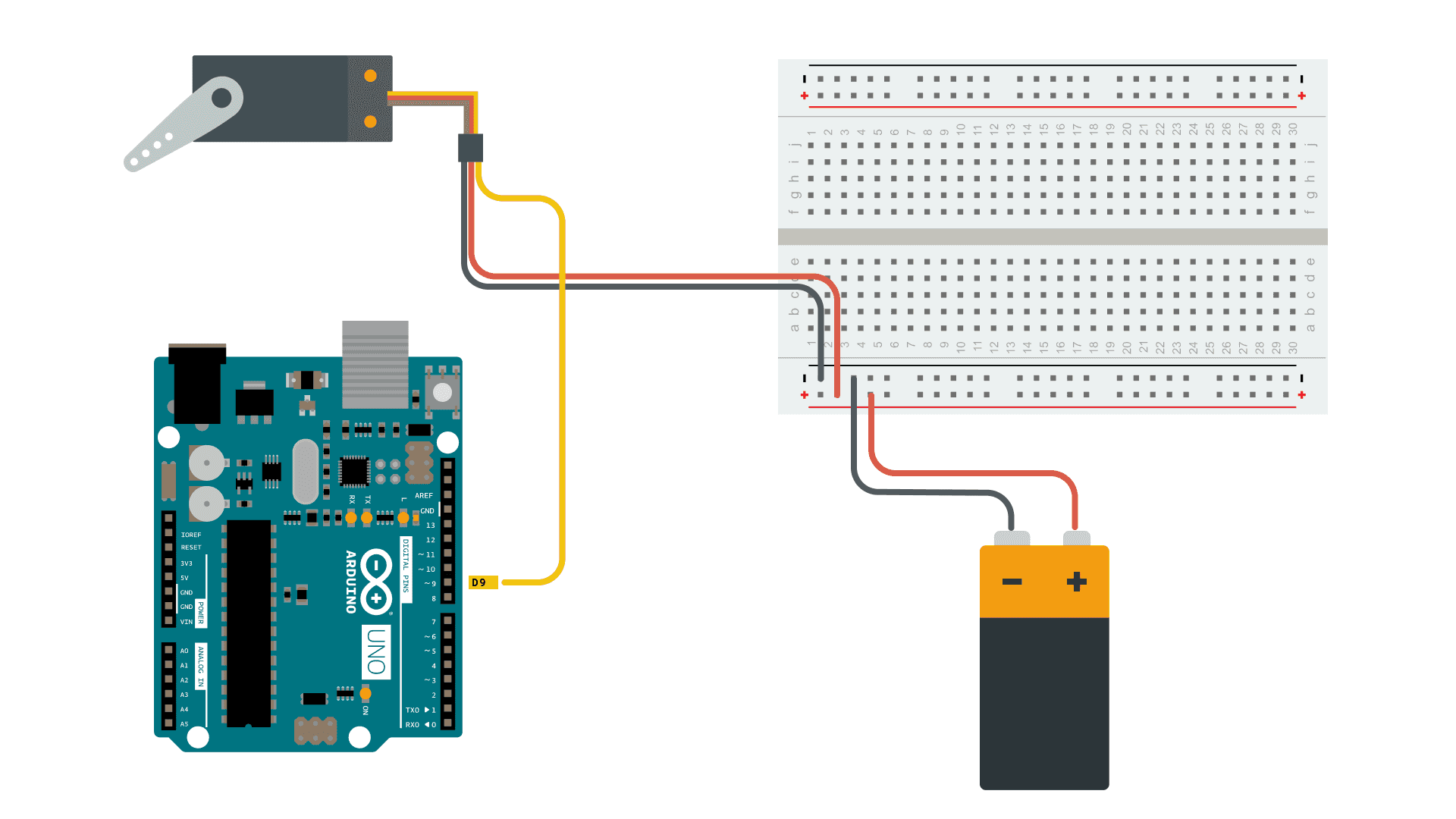
Arduino will receive 3 digits of random code from p5, when the game starts and the servo motor locks the safe box.
The user is able to enter the digits using potentiometer and button to enter the code for the safe. Turn the potentiometer to choose the digits from 0-9 and press the button to enter the digit. Arduino receives the user input and sends it to p5, which prints the message if the code is wrong or not. If the code is correct the safe opens – servo motor unlocks the safe.
Week 11 Reading reflection
While going through the text, a specific passage that took my attention is the discussion about hearing aids. Unlike glasses, whose design has undergone comparatively less change, the writer highlights the evolving nature of hearing aids, emphasizing not only the modifications in their appearance but also the constant transformation of their discreet placement.
And in the part where, ‘Simple meets universal’, the author explores the complexities of designing for special needs, especially when dealing with a minority of the population. On one hand, there is a compelling business argument against further fragmenting the market by tailoring designs for small percentages of users. The concern here is that such a specialized approach might limit the product’s reach and economic viability.
Conversely, the concept of inclusive design, also known as universal design, introduces a principle-based contention. Inclusive design, by definition, aims to cater to the entire population. This definition intertwines two critical aspects: the acknowledgment that individuals possess varying abilities, and a recognition that people may have diverse needs and preferences regardless of their abilities. The former is commonly addressed through multimodal interfaces, incorporating visual, audible, and tactile cues to accommodate those with impaired touch, hearing, and/or sight. Meanwhile, the latter is often managed through multifunctional platforms, incorporating numerous features to appeal to a broad range of users.
A central question raised by the author is whether the pursuit of universal design, aiming to accommodate a diverse user base, might inadvertently lead to overly complex designs. There is a tension between the goal of inclusivity and the risk of creating designs that are intricate and potentially challenging to use. This prompts a consideration of how truly inclusive such designs are, and whether there are insights to be gained from navigating these design complexities.
Week 11: exercises
-
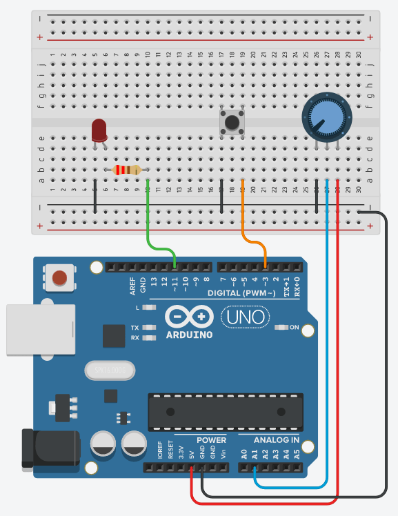
Make something that uses only one sensor on Arduino and makes the ellipse in p5 move on the horizontal axis, in the middle of the screen, and nothing on arduino is controlled by p5
let rVal = 0;
let alpha = 255;
let left = 0;
let right = 0;


function setup() {
  createCanvas(640, 360);
  noFill();
  //create an ellipse with x position changing and y (300) position constant
}

function draw() {
  background(255);


  if (!serialActive) {
    fill(0)
    text("Press Space Bar to select Serial Port", 20, 30);
  } else {
    fill(0)
    text("Connected", 20, 30);
  }
  let xPos = 300;
  xPos = map(alpha, 0, 1023, 0,640);
  ellipse(xPos, 150, 50, 50);

  console.log(alpha);
}

function keyPressed() {
  if (key == " ") {
    // important to have in order to start the serial connection!!
    setUpSerial();
  }
}
For this question, we decided to create a simple ellipse that changes direction based on the values from the potentiometer.
- make something that controls the LED brightness from p5t
function keyPressed() {
  if (key == " ") {
    // important to have in order to start the serial connection!!
    setUpSerial();
  }
  if (key== "1"){
    left = 50;
  }

  if (key== "2"){
    left = 100;
  }
  if (key== "3"){
    left = 255;
  }
  if (key =="4"){
    right = 50;
  }
  if (key =="5"){
    right = 100;
  }
  if (key =="6"){
    right =255;
  }
}
This one was pretty simple. Pressing the keys 1-6 increases/decreases the brightness of the left or right LED light. 1-3 correspond to the left, while 4-6 correspond to the right led.
- take the gravity wind example (https://editor.p5js.org/aaronsherwood/sketches/I7iQrNCul) and make it so every time the ball bounces one led lights up and then turns off, and you can control the wind from one analog sensor.
let rVal = 0;
let alpha = 255;
let left = 0;
let right = 0;
let velocity;
let gravity;
let position;
let acceleration;
let wind;
let drag = 0.99;
let mass = 20;

function setup() {
  createCanvas(640, 360);
  noFill();
  position = createVector(width/2, 0);
  velocity = createVector(0,0);
  acceleration = createVector(0,0);
  gravity = createVector(0, 0.1*mass);
  wind = createVector(0,0);
}

function draw() {
  background(255);
  applyForce(wind);
  applyForce(gravity);
  velocity.add(acceleration);
  velocity.mult(drag);
  position.add(velocity);
  acceleration.mult(0);
  ellipse(position.x,position.y,mass,mass);
  if (position.y > height-mass/2) {
      velocity.y *= -0.9;  // A little dampening when hitting the bottom
      position.y = height-mass/2;

    }
  console.log(position.y);
  if(position.y >= 330){
    left = 1;
  }
  else if(position.y <= 330){
    left = 0;
  }
  console.log(rVal);
  wind.x = map(alpha, 0, 1023, -1, 1);


  if (!serialActive) {
    fill(0)
    text("Press Space Bar to select Serial Port", 20, 30);
  } else {
    fill(0)
    text("Connected", 20, 30);
  }
}
function applyForce(force){
  // Newton's 2nd law: F = M * A
  // or A = F / M
  let f = p5.Vector.div(force, mass);
  acceleration.add(f);
}

function keyPressed() {
  if (key == " ") {
    // important to have in order to start the serial connection!!
    setUpSerial();
  }
  if(key == "1"){
    left = 1;
  }

}
For changing the wind direction, we followed similar logic to the first question. The ball changes direction based on values mapped from the potentiometer.