Final Project – Twisted Twister!

Concept Description

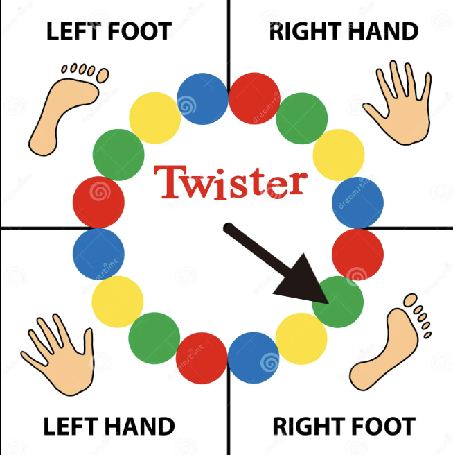
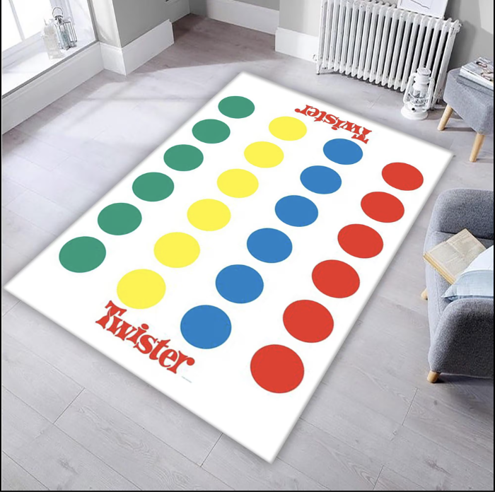
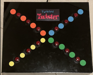
For my final project for this class, I have created Twisted Twister, a version of the popular game twister, that is played with fingers! The challenge is simple – a wheel spins, gives you a color and a hand(left or right) and you press that button with a finger of the respective hand. Every right press gives you a point and every wrong press instantly ends the game. If you manage to have all your fingers successfully on the board, you win!!

Implementation

P5.js : Most of my game is heavily reliant on the p5.js side since I use it to control the entire game logic and display. In the game I have a wheel that spins based on speech recognition. For this I’ve used the p5.speech library that does speech recognition using API functionality. The wheel in itself, is an array of equal divisions of 4 colors. While the wheel is static, there is a black spinner, that’s the one that moves and stops on a particular section and the center of the wheel displays the color. The hand the user has to use is also mentioned on the top with the same color with the intent of making it easier for the user without getting confused with so many bright colors on the screen.

Once the user presses the required switch, they have to continue holding it. I have created an array to track the switches which are already pressed and I compare it with the array of switch states I obtain from the arduino to compare the switch states at various points in the game. If a switch is correct and wasn’t already pressed, the score adds and for a wrong switch the game ends.

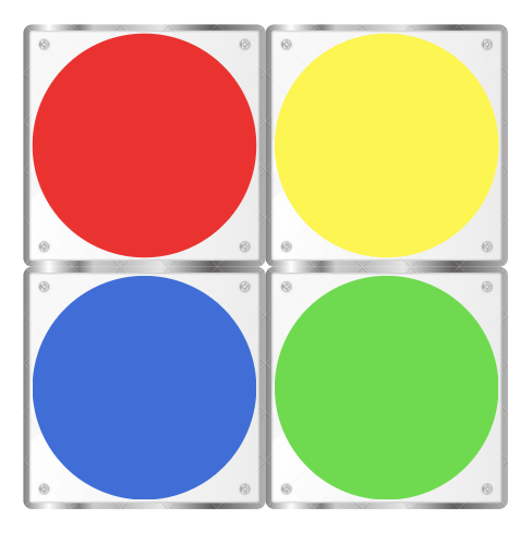
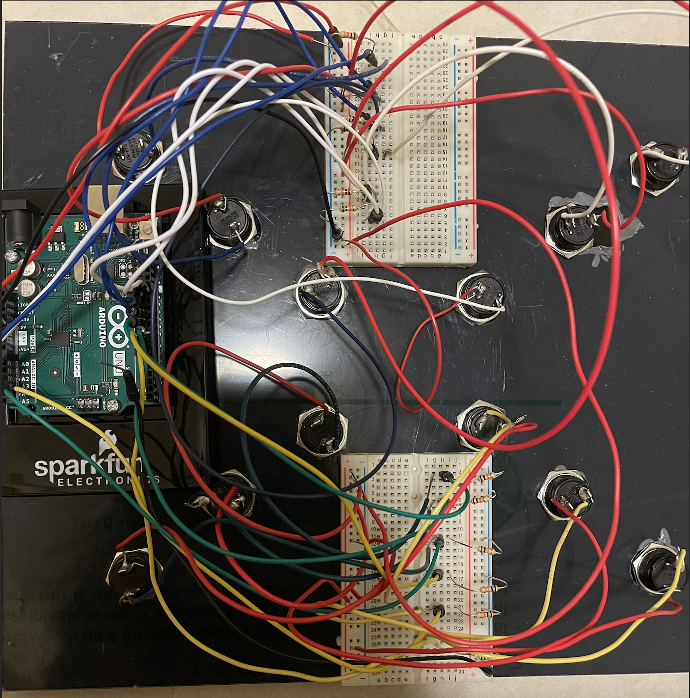
Arduino: From the arduino side, it is pretty simple. I have 12 switches, 3 of each of the 4 colors, whose states I obtain in the form of a string but then use it in p5js in the form of an array.

const int redSwitch1 = 13;
const int redSwitch2 = 12;
const int redSwitch3 = A0;
const int blueSwitch1 = 11;
const int blueSwitch2 = 10;
const int blueSwitch3 = A1;
const int greenSwitch1 = 9;
const int greenSwitch2 = 8;
const int greenSwitch3 = A2;
const int yellowSwitch1 = 7;
const int yellowSwitch2 = 6;
const int yellowSwitch3 = A3;

void setup() {
  Serial.begin(9600);
  pinMode(redSwitch1, INPUT_PULLUP);
  pinMode(redSwitch2, INPUT_PULLUP);
  pinMode(redSwitch3, INPUT_PULLUP);
  pinMode(blueSwitch1, INPUT_PULLUP);
  pinMode(blueSwitch2, INPUT_PULLUP);
  pinMode(blueSwitch3, INPUT_PULLUP);
  pinMode(greenSwitch1, INPUT_PULLUP);
  pinMode(greenSwitch2, INPUT_PULLUP);
  pinMode(greenSwitch3, INPUT_PULLUP);
  pinMode(yellowSwitch1, INPUT_PULLUP);
  pinMode(yellowSwitch2, INPUT_PULLUP);
  pinMode(yellowSwitch3, INPUT_PULLUP);
}

void loop() {
  // creating a comma-separated string to represent the states of all switches
  String switchStates = String(digitalRead(redSwitch1)) + "," +
                        String(digitalRead(redSwitch2)) + "," +
                        String(digitalRead(blueSwitch1)) + "," +
                        String(digitalRead(blueSwitch2)) + "," +
                        String(digitalRead(greenSwitch1)) + "," +
                        String(digitalRead(greenSwitch2)) + "," +
                        String(digitalRead(yellowSwitch1)) + "," +
                        String(digitalRead(yellowSwitch2)) + "," +
                        String(digitalRead(redSwitch3)) + "," +
                        String(digitalRead(blueSwitch3)) + "," +
                        String(digitalRead(greenSwitch3)) + "," +
                        String(digitalRead(yellowSwitch3));

  // sending the string data to p5.js
  Serial.println(switchStates);
  delay(500);
  
}


Interaction design: In terms of interaction design, constructing the physical aspects and combining p5js and arduino, it was somewhat frustrating because of the amount of errors but also my favorite part of the project (specifically soldering!! I found myself in the lab soldering my million wires at 8am in the morning and it was therapeutic!!).

I have chosen to place the 12 switches in diagonal rows onto an acrylic board. Since I had multiple wires, I decided to make a box so the wires can go inside without causing a visual mess. The laser cutting took a lot of time but eventually worked out (super grateful to all the lab assistants for helping me). I wanted to use switches bigger than the ones in our kit and couldn’t find as many with different colors, I put circle stickers beside these buttons indicating what color they belong to. Assembling and serial communication was easy. The only part of the interaction that took me the most time was the speech recognition. While the code worked perfectly sometimes, it would randomly get disconnected in the middle and it was difficult to come up with an alternative way to control spinning the wheel without speech recognition and hands. 

Aspects that I’m proud of

One of my biggest challenges was coming up with an idea for this project. Either the idea was too vague or too ambitious. Once I decided on this game I had constant doubts of whether or not it would be fun but after the laughs during the user testing, I think it would pass off as good enough for a first timer. 

In terms of code, I’m really happy with the speech recognition and while I did get a reference for how to make the wheel spin, I had to break the code down and modify it a lot to make it work with my game logic and I’m really happy it worked out finally!! I found a fix for the speech recognition disconnection and now it works almost all the time! I found it relaxing to keep stretching my fingers for playing this game as they’d become stiff from hours of typing!!

Future improvements

I would want to try to blackout the sections of the wheels that are already visited so the user wouldn’t have to pass it manually if the same color appears and there’s no switch of that color left. I want to make my circuit and code more organized that what I currently have. I could also consider adding a microphone closer to the user to make the speech recognition more efficient. Overall I’m really happy with the way it turned out but would love to make this more fun and engaging with more time in hand.

References

Speech Recognition: https://github.com/shiffman/A2Z-F18

Spinning wheel: p5.js Web Editor | Spinning Wheel

Final Project – Production, Progress & User Testing

My project is finally coming along! After a lot of debugging, failed laser cutting attempts and design fixes, I finally have something to test with my friends!

My project, a single player, finger version twister game has a wheel that spins based on the User saying start-stop and then displays the colors and the hand they need to use and the users just press the switches. Having all the fingers on the board correctly is a win and any wrong attempt is an immediate end to the game. 

Are they able to figure it out? Yes, it was evident from the instructions page on what they had to do.

 Where do they get confused and why? There wasn’t anything as confusing that they found as it was easy to navigate. The only part of it that was confusing the first time I tested this were the switches. Since the switches are maroon in color they get mistaken as the red buttons. However my intent is to have colored stickers around each button to show which color it belongs too.

Do they understand the mapping between the controls and what happens in the experience? Yes they were able to understand this as the wheel showed which color and even the hand depicted the color on screen making it easier to follow. Sometimes it got a little tricky but that is part of the game where you need a few seconds to process the color and hand when you see so many together.

What parts of the experience are working well? What areas could be improved?

The colors, switches, scores are working well. My only problem is the speech recognition. It is very conditional as sometimes it worked flawlessly and sometimes it just wouldn’t recognize the words, As you can see in the videos below. Since there isn’t anything wrong with the code, I’m not sure how to fix it so I’m looking for alternate ways to control this without the usage of hands since that is not possible. It can get a little frustrating if the person has to keep saying start and stop to get it right and finally get the wheel moving, it might also be too loud. So I’m thinking of shifting it to just one word thats easily capturable and then the wheel would automatically stop after 2 seconds to slightly make this better. But apart from this I will try to see if i can use any other sensors to fix this issue as I want the experience to be as interactive as it is with the sound.

Works: https://youtu.be/o5YWcVglcbk

Stop working after 60-90 seconds: https://youtu.be/eyu1sFvJHdc

What parts of your project did you feel the need to explain? How could you make these areas more clear to someone that is experiencing your project for the first time?

The maroon colored switches! I’m not sure if i should paint them as that would ruin the feel of it. Maybe i can try cutting the stickers and pasting them on the switches to make this clearer.

Final Project Proposal – Twisted Twister!

Board games have always captured my interest, and for my final project, I’ve decided to reimagine the classic multiplayer game, Twister, by transforming it into an engaging solo experience. In this adapted version, I aim to introduce interactive elements, to enhance the traditional Twister setup.

Game Components:

In the standard version of the game, participants spin a wheel to determine a color and a designated body part (hands or feet). Subsequently, players must position the indicated body part onto the corresponding colored circle on the Twister mat. The objective is to avoid losing balance, and if the player falls down, they lose. For the physical setup in my version, I plan to craft the Twister mat using acrylic sheets. Under each colored circle, I will integrate force sensors to detect whether a player has placed their palm or foot on the designated spot. This modification eliminates the need for multiple players while retaining the essence of the original game.

Spinning wheel


Digital Interface with p5js:

Utilizing the p5js interface, I intend to create a virtual spinner that dictates the next move for the player. p5js will not only control the wheel spinning but also manage the game score and determine win/loss conditions and the start & end of the game.

Additional Gameplay Elements:

To introduce a new challenge, I plan to incorporate ultrasonic sensors. In the classic game there is one option on the wheel that if landed on, the users have to keep their body part in the air. In this version, When the wheel lands on a specific option, players must extend their hands or feet to a particular distance, as detected by the sensors. 

Wheel Spinning Mechanism: Considering the physical nature of the game that actively uses the player’s hands, I’m exploring two potential options for spinning the wheel through p5js instead of directly clicking it on the laptop. One approach involves a switch on the Twister mat that, when pressed, triggers the p5js interface to spin the wheel. Alternatively, I’m considering a voice-activated mechanism where saying the word ‘spin’ initiates the wheel rotation.

Twister mat with acrylic sheets

Arduino Circuit: The Arduino circuit will be straightforward, connecting switches and force sensors to the Twister mat. However, I’m intrigued by the possibility of incorporating flex sensors/motors to introduce more complexity and fun to the game. These additions could potentially respond to the player’s movements, making the experience even more interactive.

Considerations:

While developing the game, I recognize the need to redefine the losing condition for a single-player setup. Unlike the traditional game where a player falls to signify defeat, I aim to explore alternative practical criteria that maintain the challenge and excitement without relying on physical falls in a solo context. By combining physical and digital elements, along with creative twists to the gameplay, I hope to transform Twister into a captivating and entertaining game experience.

Final Project Idea

For the final project of this class, I have a lot of vague ideas but need to decide on one based on its practicality! I know what I want to use for the project but I’m trying to figure out if I want to make that in an interactive game form or an art form. Either an interactive art that takes input from the arduino through different body movements or a game that works on the same mechanism.

Things that I’m sure of:

  1. Including the whole body as a part of this as after the readings from this class, one of my biggest takeaways has been using the entire body or atleast just more than hands for creating an immersive experience.
  2. I want to try to use flex and force sensors since I’ve never had a chance to use them for the weekly assignments yet
  3. I’m a person who has the shortest attention span and loses interest very quickly so I want to make something that is long lasting fun and not something that looses it charm after 2 minutes.

Week 11 – In class exercises

  1. make something that uses only one sensor  on Arduino and makes the ellipse in p5 move on the horizontal axis, in the middle of the screen, and nothing on arduino is controlled by p5For this exercise, I modified the p5js code using a potentiometer on the arduino. Different values of the potentiometer are mapped to the x coordinates of the ellipse. This makes it move across the horizontal axis in the middle of the screen. The arduino code remains the same as the example code.
let y=height/2;
let x = 0;
let left = 0; // True (1) if mouse is being clicked on left side of screen
let right = 0; // True (1) if mouse is being clicked on right side of screen

function setup() {
  createCanvas(640, 480);
  textSize(18);
}

function draw() {
  background(255);
  // one value from Arduino controls the background's red color
  fill(255, 0, 255, map(x, 0, 1023, 0, 255));
  ellipse(map(x, 0, 1023, 0, width), 30, 30);

  // the other value controls the text's transparency value

  if (!serialActive) {
    text("Press Space Bar to select Serial Port", 20, 30);
  } else {
    text("Connected", 20, 30);
  }


function keyPressed() {
  if (key == " ") {
    // important to have in order to start the serial connection!!
    setUpSerial();
  }
}

// This function will be called by the web-serial library
// with each new *line* of data. The serial library reads
// the data until the newline and then gives it to us through
// this callback function
function readSerial(data) {
  ////////////////////////////////////
  //READ FROM ARDUINO HERE
  ////////////////////////////////////

  if (data != null) {
    // make sure there is actually a message
    // split the message
    let fromArduino = split(trim(data), ",");
    // if the right length, then proceed
    if (fromArduino.length == 2) {
      // only store values here
      // do everything with those values in the main draw loop
      
      // We take the string we get from Arduino and explicitly
      // convert it to a number by using int()
      // e.g. "103" becomes 103
      y = int(fromArduino[0]);
      x = int(fromArduino[1]);
    }

    //////////////////////////////////
    //SEND TO ARDUINO HERE (handshake)
    //////////////////////////////////
    let sendToArduino = left + "," + right + "\n";
    writeSerial(sendToArduino);
  }
}

2. make something that controls the LED brightness from p5

again tweaking the previous p5js and arduino codes, for this one, Pressing the up or down arrow key on the keyboard, run through p5js, increases or decreases the brightness of the leds on the arduino respectively. this was done using the concept of pulse width modulation.

p5js code:

let rVal = 0;
let alpha = 255;
let brightness = 0;

function setup() {
  createCanvas(640, 480);
  textSize(18);
}

function draw() {
  background(map(rVal, 0, 1023, 0, 255), 255, 255);
  fill(255, 0, 255, map(alpha, 0, 1023, 0, 255));

  if (!serialActive) {
    text("Press Space Bar to select Serial Port", 20, 30);
  } else {
    text("Connected", 20, 30);
    text('rVal = ' + str(rVal), 20, 50);
    text('alpha = ' + str(alpha), 20, 70);
  }
}

function keyPressed() {
  if (key == " ") {
    setUpSerial();
  } else if (keyCode === UP_ARROW) {
    brightness = constrain(brightness + 20, 0, 255);
    sendToArduino();
  } else if (keyCode === DOWN_ARROW) {
    brightness = constrain(brightness - 20, 0, 255);
    sendToArduino();
  }
}

function sendToArduino() {
  let sendToArduino = brightness + "\n";
  writeSerial(sendToArduino);
}

function readSerial(data) {
  if (data != null) {
    let fromArduino = split(trim(data), ",");
    if (fromArduino.length == 2) {
      rVal = int(fromArduino[0]);
      alpha = int(fromArduino[1]);
    }
    let sendToArduino = brightness + "," + brightness + "\n";
    writeSerial(sendToArduino);
  }
}


arduino code:

int leftLedPin = 2;
int rightLedPin = 5;

void setup() {
  // Start serial communication so we can send data
  // over the USB connection to our p5js sketch
  Serial.begin(9600);

  // We'll use the builtin LED as a status output.
  // We can't use the serial monitor since the serial connection is
  // used to communicate to p5js and only one application on the computer
  // can use a serial port at once.
  pinMode(LED_BUILTIN, OUTPUT);

  // Outputs on these pins
  pinMode(leftLedPin, OUTPUT);
  pinMode(rightLedPin, OUTPUT);

  // Blink them so we can check the wiring
  digitalWrite(leftLedPin, HIGH);
  digitalWrite(rightLedPin, HIGH);
  delay(200);
  digitalWrite(leftLedPin, LOW);
  digitalWrite(rightLedPin, LOW);

  // start the handshake
  while (Serial.available() <= 0) {
    digitalWrite(LED_BUILTIN, HIGH); // on/blink while waiting for serial data
    Serial.println("0,0"); // send a starting message
    delay(300);            // wait 1/3 second
    digitalWrite(LED_BUILTIN, LOW);
    delay(50);
  }
}
void loop() {
  // wait for data from p5 before doing something
  while (Serial.available()) {
    digitalWrite(LED_BUILTIN, HIGH); // led on while receiving data

    int left = Serial.parseInt();
    int right = Serial.parseInt();
    if (Serial.read() == '\n') {
      Serial.print("Left: ");
      Serial.print(left);
      Serial.print(", Right: ");
      Serial.println(right);

      analogWrite(leftLedPin, left);
      analogWrite(rightLedPin, right);
    }
  }
  digitalWrite(LED_BUILTIN, LOW);
}


3. take the gravity wind example (https://editor.p5js.org/aaronsherwood/sketches/I7iQrNCul) and make it so every time the ball bounces one led lights up and then turns off, and you can control the wind from one analog sensor

I found this one to be a little challenging but eventually made it work. the ball bounces with the same logic and physics from the example. Each time it touches the ground, using a boolean variable ballOnGround, it is equated to 1 or 0. this is then sent to the arduino where the LED turns on if it is 1. For the sensor contrilling wind, Im using a photoresitor whose values are mapped to the x coordinate of the wind vector. The ball moves faster when the value is larger. MouseClicking restarts the movement of the ellipse. The issue I face is slight delay in the led lighting up.

video:

p5.js Code:

let velocity;
let gravity;
let position;
let acceleration;
let wind;
let drag = 0.99;
let mass = 20;
let ballOnGround=1;
function setup() {
  createCanvas(640, 360);
  noFill();
  position = createVector(width/2, 0);
  velocity = createVector(0,0);
  acceleration = createVector(0,0);
  gravity = createVector(0, 0.5*mass);
  wind = createVector(0,0);
}

function draw() {
  background(255);
  
  if (!serialActive) {
    text("Press Space Bar to select Serial Port", 20, 30);
  } else {
    applyForce(wind);
    applyForce(gravity);
    velocity.add(acceleration);
    velocity.mult(drag);
    position.add(velocity);
    acceleration.mult(0);

    fill(0);
    ellipse(position.x, position.y, mass, mass);
    if (position.y > height - mass / 2) {
      velocity.y *= -0.9; // A little dampening when hitting the bottom
      position.y = height - mass / 2;
      ballOnGround = 1;
      let sendToArduino = ballOnGround + "\n";
    writeSerial(sendToArduino);
    ballOnGround = 0;
    sendToArduino = ballOnGround + "\n";
    writeSerial(sendToArduino);
    } else {
      ballOnGround = 0;
    }
  }
  
  
  if (mouseIsPressed) {
      restartSketch();
    }
}

function applyForce(force){
  // Newton's 2nd law: F = M * A
  // or A = F / M
  let f = p5.Vector.div(force, mass);
  acceleration.add(f);
}


function keyPressed() {
  if (key == " ") {
    // important to have in order to start the serial connection!!
    setUpSerial();
  } 
}

function readSerial(data) {
  if (data != null) {
    // make sure there is actually a message
    // split the message
    let fromArduino = split(trim(data), ",");
    // if the right length, then proceed
    if (fromArduino.length == 1) {
      // only store values here
      // do everything with those values in the main draw loop
      let photoresistor = int(fromArduino[0]);
      
      //change the wind based on the photoresistor readings
      wind.x = map(photoresistor, 0, 1000, -5, 5);
      
    }

    //////////////////////////////////
    //SEND TO ARDUINO HERE (handshake)
    //////////////////////////////////
    // let sendToArduino = ballOnGround + "\n";
    // writeSerial(sendToArduino);
  }
}


function restartSketch() {
  // Reset relevant variables to their initial values
  position = createVector(width / 2, 0);
  velocity = createVector(0, 0);
  acceleration = createVector(0, 0);
  wind = createVector(0, 0);
  mass = 50;
  ballOnGround = 0;
}

arduino code:

int ledPin = 2;
const int photoresistorPin = A0;

void setup() {
  Serial.begin(9600);
  pinMode(LED_BUILTIN, OUTPUT);
  pinMode(ledPin, OUTPUT);
  pinMode(photoresistorPin, INPUT);

  // start the handshake
  while (Serial.available() <= 0) {
    digitalWrite(LED_BUILTIN, HIGH); // on/blink while waiting for serial data
    Serial.println("0,0");           // send a starting message
    delay(300);                      // wait 1/3 second
    digitalWrite(LED_BUILTIN, LOW);
    delay(50);
  }
}

void loop() {
  // wait for data from p5 before doing something
  while (Serial.available()) {
    digitalWrite(LED_BUILTIN, HIGH); // led on while receiving data
    int ballOnGround = Serial.parseInt();
    if (Serial.read() == '\n') {
      int photoresistorValue = analogRead(photoresistorPin);

      // Send photoresistor value to p5.js
      Serial.println(photoresistorValue);
      digitalWrite(ledPin, HIGH);
      digitalWrite(ledPin, LOW);
      // Control the LED based on the bouncing state.
      if (ballOnGround == 1) {
        digitalWrite(ledPin, HIGH);
      } else {
        digitalWrite(ledPin, LOW);
      }
    }
  }
  digitalWrite(LED_BUILTIN, LOW);
}


Reading Reflections – Week 11!

After this thought-provoking read, I wholeheartedly feel that a design should be universally accessible, catering to everyone’s needs. Imagine the convenience of a singular product that eliminates the need for individuals to ponder, “Will this suit my requirements?” or “Is this tailored for a specific group?” Although implementing such universality might pose challenges for designers, the benefits could be substantial.

This approach would eradicate the apprehension associated with designing for differently-abled individuals, as it wouldn’t be perceived as mediocre or subpar when designed for a broader audience. The return of a sense of ‘delight’ in everyday products could be achieved through a more inclusive design, fostering unity rather than segregation. While certain disabilities may require specialized technology, there are aspects we can universalize for everyone.

What particularly intrigued me is the question of whether we should project a positive image or refrain from projecting an image altogether. Striking a balance that avoids exclusion and encourages accommodation is crucial. Examples related to fashion, discretion, and simplicity prompted me to contemplate how, as someone pursuing interactive media, I can contribute to bridging the gap between realism and functionalism. The oldest ipod nano that my father owned used to be my favorite device. The familiarity of the tracker wheel mentioned in the text resonates with me.

Reflecting on my five-year-old self effortlessly navigating it, I realize the design and feedback were exceptionally well-executed. It serves as a possibility of achieving a harmonious intersection of simplicity, functionality, and aesthetics—providing inspiration for designers and me, particularly to aim to strike that delicate balance.The idea of embracing cultural differences in embracing fashion and technology did sound a little strange at first but I agree that it would definitely be a call to action for more innovative and accessible design.

Week 10 – Musical Instrument!

Concept:
Our musical is sort of a 3 note piano with 3 octaves. There are three buttons that each play a specific note (A, B and C), and an ultrasonic sensor to measure the distance which in turn specifies the octave the user wants to play the notes in (3,4,5). The nearest interval plays the notes in the third octave, the next plays the notes in the fourth interval which sounds higher than the first interval and the last interval plays the notes in the fifth interval which sound higher than the middle interval. The buttons are controlled by switches that act as our main digital input and trigger specific notes depending on the secondary input which is the analog input from the ultrasonic sensor that specifies the octave to play the notes. We have also included an LED light that blinks when the instrument is first started and when the user has exceeded the range of the input from the ultrasonic sensor.

Notes played: A3, A4, A5, B3, B4, B5, C3, C4, C5.

Process & Highlights:
It was an interesting process trying to figure out how to connect everything together the right way and to get the ultrasonic sensor to work as expected, but once we figured everything out it was pretty easy to follow through the code. It helped to work as a team because we brainstormed the idea together and worked on the logic of the code and implemented it together which was more fun than working individually. I would say the highlight was finally getting it to work the way we wanted it to.


Here is a video demo of our instrument:

Code:

const int trigPin = 9;
const int echoPin = 10;
const int ledPin = 13;
const int buzzerPin = 8;
const int switchPin1 = 2; // Pin for the first switch
const int switchPin2 = 3; // Pin for the second switch
const int switchPin3 = 4; // Pin for the third switch

float duration, distance;

// Melodies
#include "pitches.h"

int melody11 = NOTE_C3;
int melody12 = NOTE_C4;
int melody13 = NOTE_C5;
int melody21 = NOTE_A3;
int melody22 = NOTE_A4;
int melody23 = NOTE_A5;
int melody31 = NOTE_B3;
int melody32 = NOTE_B4;
int melody33 = NOTE_B5;


void playNote(int melody){
  tone(buzzerPin, melody, 800);
  delay(1000);
}

void setup() {
  pinMode(trigPin, OUTPUT);
  pinMode(echoPin, INPUT);
  pinMode(ledPin, OUTPUT);
  pinMode(buzzerPin, OUTPUT);
  pinMode(switchPin1, INPUT_PULLUP);
  pinMode(switchPin2, INPUT_PULLUP);
  pinMode(switchPin3, INPUT_PULLUP);
  Serial.begin(9600);
}

void loop() {
  digitalWrite(trigPin, LOW);
  delayMicroseconds(2);
  digitalWrite(trigPin, HIGH);
  delayMicroseconds(10);
  digitalWrite(trigPin, LOW);

  duration = pulseIn(echoPin, HIGH);
  distance = (duration * 0.0343) / 2;


  if (distance < 10) {
    Serial.println("Distance: 1");
    digitalWrite(ledPin, HIGH);   // Turn on the LED

    if (digitalRead(switchPin1) == LOW) {
      playNote(melody11); 
    } else if (digitalRead(switchPin2) == LOW) {
      playNote(melody21); 
    } else if (digitalRead(switchPin3) == LOW) {
      playNote(melody31); 
    }

  } else if (distance < 20) {
    Serial.println("Distance: 2");
    digitalWrite(ledPin, HIGH);   // Turn on the LED

    if (digitalRead(switchPin1) == LOW) {
      playNote(melody12); 
    } else if (digitalRead(switchPin2) == LOW) {
      playNote(melody22); 
    } else if (digitalRead(switchPin3) == LOW) {
      playNote(melody32); 
    }

  } else if (distance < 30) {
    Serial.println("Distance: 3");
    digitalWrite(ledPin, HIGH);   // Turn on the LED
    digitalWrite(ledPin, LOW);
    digitalWrite(ledPin, HIGH);
    if (digitalRead(switchPin1) == LOW) {
      playNote(melody13); 
    } else if (digitalRead(switchPin2) == LOW) {
      playNote(melody23); 
    } else if (digitalRead(switchPin3) == LOW) {
      playNote(melody33); 
    }

  } else {
    Serial.println("Distance: 4");
    //Blink
    digitalWrite(ledPin, LOW);    // Blink the LED
    digitalWrite(ledPin, HIGH);
    digitalWrite(ledPin, LOW);
    digitalWrite(ledPin, HIGH);
    digitalWrite(ledPin, LOW);
    digitalWrite(ledPin, HIGH);
    digitalWrite(ledPin, LOW);
    noTone(buzzerPin);             // Turn off the buzzer
  }
}

Reflections:
We found this exercise a bit harder than the previous one but it was more fun to implement. If we could change one thing about our instrument, it would be to maybe have a screen display the note being played as well as more buttons to replicate an actual piano with more octaves.Additionally, we would love to find a way to incorporate more creativity within.

Done by Mirette & Keya

References:

pitches.h used from tone()

Reading Reflections – week 10!

“The only reason your mind doesn’t explode every morning from the sheer awesomeness of your balletic achievement is that everyone else in the world can do this as well.” I think this reading made so much sense after the previous reading, Physical computing greatest hits(and misses). After seeing pieces like video mirrors and the body-as-a-cursor, or after actively using facial recognition on phones where our body is at command and not just our fingers, I definitely think the future of interaction goes way beyond the capacities of our hands. 

The first in-class assignment we had for the physical computing part of the class, where we had to make a creative switch that did not use hands, it was very hard to think of something to make. This does highlight the challenge that we need to break away from established norms and thinking beyond the limitations of familiar interaction methods. 

A question that stuck with me was how do we manipulate things? But how I perceive his explanation on this and think about it is, how do we manipulate them into a way that they are intuitive? Will the dynamic mediums Bret Victor talks about, be intuitive right from the start or will they take years of trials, feedbacks and usage to finally be called familiar and usable by ‘common sense’. I also appreciate the follow up article with his responses to the comments. His reply to the brain interfaces comment is quite nice and reassuring in a world where people believe automating all the work is way more efficient since humans are way more prone to making errors. I also like the insight on the psychological and cognitive aspects but not fully clear on the Matti Bergstrom quote about finger blindness.

My takeaway from this reading would be that our interaction with digital media and devices should not have consequences to our physical body and the idea of everything we do mediated by a computer might not be a good one.

Reading Reflections – Week 9!

Making Interactive Art: Set the Stage, Then Shut Up and Listen

I found this reading quite interesting. The natural instinct of wanting to help and make things easier for us sometimes makes us forget the fact that we might be oversharing or spoiling the experience. My takeaway from this reading would be the point Tigoe made about listening. Oftentimes in the excitement or nervousness of showing something to others, it’s easy to forget to actually see how they feel about it while interacting with it. When I’m showing my friends and family the weekly assignments from this class, I do expect their encouragement and feedback but I don’t think I fully listen or focus on their reactions, only because I’m so focused that the project is delivered exactly the way I want it to be. For my midterm project, I had an interactive Christmas tree designing component. I remember telling someone where exactly to place the lights because I had imagined it that way, forgetting that that’s for them to decide. I would definitely introspect more on this, shut up and listen after I’ve set the stage for people.

Physical Computing’s Greatest Hits (and misses)

I liked the idea of ‘meditation helpers’. While I know that it cannot fully capture the human state of mind and the machine may just be making educated guesses about how to do so by looking at heart and breath rates, the very intent of using physical computing for something like this to get you to a calmer and meditative state interests me. It left me thinking for a solid fifteen minutes on ways that we could actually make this work with more accuracy. This complements the purpose of the reading and the idea that even though themes may be recurring they allow a lot of room for originality. I also really appreciate having a blog for this class that lets us view and take inspiration from others’ works. Sometimes I feel like my ideas would be repetitive of the previously done ones but after this reading I fully agree that all pieces, even if they use the exact same materials, are completely different renditions and convey unique and individual thoughts.

Week 9 – Digital Analog Mood Lamp!

Concept

For this week’s assignment, I drew inspiration from Mood Lamps. Mood Lighting helps create a calming and soothing atmosphere and can invoke different moods depending on the colors you set it at. I’ve tried to create a very basic version of this.

Process

My idea was to use an RGB Led, a digital switch for digital input and a potentiometer for analog input for this. However, certain values of potentiometer readings did not work and hence I added separate green and yellow LEDs that would light up instead. There is a circular ring of moods around the potentiometer. You can move the arrow towards the mood you’d like to set it up at. The potentiometer values are mapped to rgb values that are then displayed on the RGB Led. If the digital switch is pressed, alot of colors get displayed automatically. In this case the mapping is between time and the rgb values

I had some trouble figuring out the working of the digital switch but with some references and trial and errors, I eventually figured it out to work somewhat like desired.

code:

void setup() {
  pinMode(RGB_RED_PIN, OUTPUT);
  pinMode(RGB_BLUE_PIN, OUTPUT);
  pinMode(RGB_GREEN_PIN, OUTPUT);
  pinMode(GREEN_LED_PIN, OUTPUT);
  pinMode(YELLOW_LED_PIN, OUTPUT);
  pinMode(SWITCH_PIN, INPUT);  

  Serial.begin(9600);  
}

void loop() {
  int switchState = digitalRead(SWITCH_PIN);
    Serial.print("Switch State: ");
Serial.println(switchState);

  if (switchState == HIGH) {

     int currentTime = millis();
  int period = 3; 
  int rgbValue = map(currentTime % period, 0, period, 0, 1535);

  // convert the RGB value to individual color components
  int red, green, blue;

  if (rgbValue < 256) {
    red = 255;
    blue = rgbValue;
    green = 0;
  } else if (rgbValue < 512) {
    red = 511 - rgbValue;
    blue = 255;
    green = 0;
  } else if (rgbValue < 768) {
    red = 0;
    blue = 255;
    green = rgbValue - 512;
  } else if (rgbValue < 1024) {
    red = 0;
    blue = 1023 - rgbValue;
    green = 255;
  } else if (rgbValue < 1280) {
    red = rgbValue - 1024;
    blue = 0;
    green = 255;
  } else {
    red = 255;
    blue = 0;
    green = 1535 - rgbValue;
  }

  // setting RGB LED colors
  analogWrite(RGB_RED_PIN, red);
  analogWrite(RGB_BLUE_PIN, blue);
  analogWrite(RGB_GREEN_PIN, green);


    // separate green LED
    digitalWrite(GREEN_LED_PIN, HIGH);

    //separate yellow LED
    digitalWrite(YELLOW_LED_PIN, LOW);
  } else {
  int potentiometerValue = analogRead(POTENTIOMETER_PIN);
  int rgbValue = map(potentiometerValue, 0, 1023, 0, 1535);

  // potentiometer value to the serial monitor
  Serial.print("Potentiometer Value: ");
  Serial.println(potentiometerValue);

  int red;
  int blue;
  int green;
  
  if (rgbValue < 256) {
    red = 255;
    blue = rgbValue;
    green = 0;
  }
  else if (rgbValue < 512) {
    red = 511 - rgbValue;
    blue = 255;
    green = 0;
  }
  else if (rgbValue < 768) {
    red = 0;
    blue = 255;
    green = rgbValue - 512;
  }
  else if (rgbValue < 1024) {
    red = 0;
    blue = 1023 - rgbValue;
    green = 255;
  }
  else if (rgbValue < 1280) {
    red = rgbValue - 1024;
    blue = 0;
    green = 255;
  }
  else {
    red = 255;
    blue = 0;
    green = 1535 - rgbValue;
  }
  
  analogWrite(RGB_RED_PIN, red);
  analogWrite(RGB_BLUE_PIN, blue);
  analogWrite(RGB_GREEN_PIN, green);

  // separate green and yellow LEDs based on potentiometer value
  if (potentiometerValue >= 340 && potentiometerValue <= 510) {
    digitalWrite(GREEN_LED_PIN, HIGH);  // Turn on green LED
    digitalWrite(YELLOW_LED_PIN, LOW);  // Turn off yellow LED
  } else if (potentiometerValue >= 165 && potentiometerValue <= 342) {
    digitalWrite(GREEN_LED_PIN, LOW);   // Turn off green LED
    digitalWrite(YELLOW_LED_PIN, HIGH);  // Turn on yellow LED
  } else {
    digitalWrite(GREEN_LED_PIN, LOW);   // Turn off green LED
    digitalWrite(YELLOW_LED_PIN, LOW);  // Turn off yellow LED
  }
  
  delay(100);  
  }

  // delay to avoid flooding the serial monitor with data
  delay(100);
}

Reflections

I really enjoyed this and was able to explore different sensors as I tried out the ultrasonic resistor, potentiometer and photoresistor before deciding which one to go forward with. I did have some issues while coding but managed to make something similar to what I had expected. For future improvements, I could maybe use something transparent/translucent to cover the leds and make the light intensify more like in usual lamps.

References

rgb led