Starting from my very first Intro to IM assignment, I have been trying to combine the possibilities of Interactive Media and my passion for card magic. The initial idea for a project like this came to me as I remembered when once I saw an automatic card dealer that swiftly deals the appropriate number of cards to the selected number of players, and some models even shuffle the cards before dealing! Some of these models are sold commercially, but I wanted to go a step further – to try to make a card dealing machine that would help the user get a competitive edge over the other players – which is a natural extension to a device like this for a magician. Here is an example of one of those machines that are sold commercially.
Example of an automatic card dealer
Although there was a handful of card-dealer projects online, I could not find any project that would combine card detection and dealing except one, which was not feasible to make in the scope of the class. I had to find projects and information from all over the web and put them together into a cohesive whole, which was a challenging and a time-consuming task.
Physical Parts:
I found this video on YouTube that employs a close mechanism to what I wanted to create. Hence, I used some of the models that they created to 3D print a tray to hold the cards, a wheel that will dispense the cards, and the handle to hold the motor that the wheel is going to be attached to. I had to learn some use of a 3D modeling software to design my project accordingly, and I used FreeCAD to make all the necessary measurements. After some issues with 3D printing and with the help of Professor Aya the 3D models were successfully completed. I would some rubber string in the IM Lab that was the only fitting component that could be glued to the 3D printed wheel to dispense the cards. The rubber material was necessary to provide enough friction for the cards to be caught and moved.
The bottom platform I used is from this project (https://www.instructables.com/Rotating-Table-Tutorial-In-Progress/). The scale was modified to fit the project better.
After all the models were ready, I used the drills in the Lab to adjust the hole dimensions to fit every piece snugly. I have never worked with 3D printers before, therefore this part was quite challenging in terms of finding the right models and modifying them physically or digitally to make every piece work together. Gladly, everything was fitting in the end and it was time for time digital implementation.
Here is the final design of the device.
The servo motor for the base is fixed using cardboard and wooden blocks glued to the motor for stabilization.
The detection model: This was undoubtedly the most challenging and novel part in this project. I went through a lot of options among training models myself and searching for pre0trained models until I found a pre-trained model on Roboflow for playing card detection (https://universe.roboflow.com/augmented-startups/playing-cards-ow27d/model/4). During this learning process I understood how to use pre-trained models and understood the process of training a model myself, but I am glad that I found a pre-trained one as training it myself would be a possible, but hugely a time-consuming process. Another major challenge arose during the deployment of the model on the website. I faced a lot of technical issues until making the model work on the website that I made for the project.
P5.js:
I went with a web-implementation route for the project as the Roboflow model did not work on the web editor for P5. There a couple major parts.
if (cardValue == choice && actionDone == 0) {
    found = 1;
    console.log("FOUND");
    sendToArduino();
    actionDone = 1;
  }
This part of the code is used to signal a write once to Arduino after the detection model sees the card chosen by the user.
function sendToArduino() {
  datatosend = 1 + "\n";
  writeSerial(datatosend);
  console.log("SENT TO ARDUINO: " + datatosend);
}
This function sends a true value to Arduino once the right card is detected.
var prediction = predictions[i];
    //console.log(prediction.class);
    cardValue = prediction.class;
    var x = prediction.bbox.x - prediction.bbox.width / 2;
    var y = prediction.bbox.y - prediction.bbox.height / 2;
    var width = prediction.bbox.width;
    var height = prediction.bbox.height;
This part of the code is getting the prediction of the model, which is a string value of two characters, the first one is the value of the card – either a number or a letter, the second one indicates the suit (Heart, Club, etc.). For instance, if the card chosen by the user is the Queen of Spades, the prediction model would detect the card and output “QS”, if the card is 7 of Hearts, the model would output “7H”. Because the user is choosing the card by inputting the string value into the website, they have to use the right syntax – two characters, no spaces, all capitalized.
Arduino:
The Arduino code is working with a DC motor, as a positional Servo motor did not have enough range to push the card over the edge of the deck to dispense it. The hardship here was to set exact timing and power to the motor to dispense one card only and not more. The motor also needed to push back the rest of the cards once the needed card is pushed out.
while (Serial.available()) {
     digitalWrite(LED_BUILTIN, HIGH); // led on while receiving data
     int found = Serial.parseInt();
      if (Serial.read() == '\n') {
       if (found == 1){
        base.write(120);
        delay(1000);
        launchCard();
        base.write(60);
        delay(1000);
       }
       found = 0;

       }
  }
This part of the code is in the main loop function. Once the user’s card is found, the Servo motor rotates the tray to a different angle, dispenses the user’s card, then comes back and continues to dispense the rest of the cards.
Final Thoughts:
The goal that was set in the beginning of the project was met: a card dispensing machine that can also modify the dealing by detecting cards. The expansions on this idea can be multiple in the realm of card handling. As a magician, I can use this accessory to enrich my tricks to make the machine the machine pick the right selection by the user.
Using only the Arduino part, the machine can work as a normal dealing machine if the deck is put face-down in the machine and 2-5 people are playing a game and need cards to be dealt to them. The device can also be used to sort cards with little modification to the code. In addition to that, if the detection is to be used in an actual game where cards are being dealt face-down, a simple solution would be to cover the device from the top and sides, attach a platform in front of the tray so that the cards are dealt on top of it one by one, then simply rotate the platform 180 degrees to drop the card face down on the table. That way the dealing would seem fair, but the camera can still see the cards from the top and make manipulations accordingly.
The most challenging part of the project was finding and learning how to use a machine learning model and integrating it into my program. However, after a long time of trying to figure it out, I learned the necessary skills of using it which will undoubtedly help me in my future projects.
I also faced some technical difficulties which I became aware of late in the project, i. e. the motor that I used had faulty wiring and was giving me inconsistent results when I thought the code of the motor was incorrect. I had to hold the wire with one of my hands during the showcase, however I was somewhat glad to find that the main issue was easily fixable with a new pair of wires. In the video below, the 3 of Clubs did not jump out at the end like the other cards because the base turned and weakened the wire connection by displacing the handle with the motor.
Overall, I reached the goal that I had set in the conception of the project idea, and I think the project was a success overall.
Cupid first took root with a simple LED heart. From the very start, I knew I wanted to incorporate this element – a beating, glowing heart that could serve as the centrepiece for an interactive experience. However, I hadn’t quite decided how to elevate it beyond just this into something more profound and immersive.
And then 💡! – what if this heart could be linked to the user’s own pulse? By integrating a pulse sensor, I could make each person’s unique heartbeat bring the LED heart to life, creating a personalised connection.
This sparked the concept for Cupid – an interactive cardboard robot that detects your heartbeat through pulse sensing, uses it to animate a glowing LED heart in its chest, and even generates humorous, randomly selected (chatGPT generated 🤭 ) “love predictions” based on your heart rate variability data.
The goal was to craft an experience that the love child of playful and whimsy. By encouraging users to form a “heart-to-heart connection” with this quirky robot, the interaction taps into something innately human – our capacity for creating emotional bonds and embracing moments of lighthearted joy.
Brainstorming:
The Process:
The Heart:
Building the pulsing LED heart for Cupid was quite a challenge. The biggest issue was that I needed 16 LEDs, but the Arduino only had 13 digital pins available. To work around this, I had to get creative and connect the LEDs in pairs using soldering.
For each pair, I soldered the negative leg of one LED to the positive leg of the other LED. Then, I soldered the negative leg of the second LED to a 330-ohm resistor to control the current. After doing this for all 8 pairs, I soldered a single wire to the positive end of each pair.
Finally, I bundled all the negative resistor legs together and connected them to a single ground wire. This way, I could control the 16 LEDs using just 8 digital pins from the Arduino.
While this wiring setup took some careful soldering work (and far more time than I’d like to admit), it allowed me to create the synchronised pulsing heart effect that became the centrepiece of Cupid. Tinkering with the soldering iron, meticulously joining the wires and components, I found an unexpected sense of satisfaction and joy in the hands-on process. It made me realise how much I enjoy working with tangible tools.
Cupid in her early stages 😋
The P5 Sketch:
After the intricate work of building Cupid’s LED heart, creating the p5.js sketch felt relatively simple. I took a hands-on approach by hand-drawing the title page illustration. Then I drew Cupid’s adorable (i’m biased) robot body. I wanted to infuse the character with warmth and likability. While the p5.js coding was more technical, the artistic process of drawing Cupid made this phase of the project very enjoyable and satisfying.
Now it was time to bring her to life through code. The p5.js sketch served as the digital heart (hehe) of this project. Here’s a breakdown of some key elements of the code:
Heart Animation: The pulsing LED heart effect was achieved by gradually reducing the size of the heart shape (heartSize) over time. This created a lifelike pulsation that synced with the user’s heartbeat.
if (state === 1 && heartSize > 50) {
  heartSize *= 0.97;  // Gradually reduce heart size to simulate the beat
}
State-Based Interaction: Cupid’s interaction was divided into different states (0, 1, and 2) to control the flow of the experience. These states determined what was displayed on the screen and how Cupid responded to user input.
switch (state) {
  case 0:
    imageMode(CENTER);
    image(text1, width / 2, height / 2);
    fill("#FED4D6");
    textSize(30);
    text("Press space bar to begin", width / 2, height - 100);
    break;
  case 1:
    imageMode(CENTER);
    image(cupidbot, width / 2, height / 2);
    drawHeart();
    fill("#FED4D6");
    textSize(40);
    if (timeHeartbeatDetected && millis() - timeHeartbeatDetected < 10000) {
      text("making heart to heart connection", width / 2, height / 10);
    } else if (timeHeartbeatDetected) {
      text("connection made. press enter to know your love prediction", width / 2, height / 10);
      displayPredictionText = true;  // Enable showing the prediction prompt
    } else {
      text("hold my hand to make a connection", width / 2, height / 10);
    }
    break;
  case 2:
    fill("#FED4D6");
    textSize(35);
    text(prediction, width / 2, height / 2);
    if (displayPredictionText) {
      noStroke();
      fill("#FED4D6");
      rect(width / 2 - 100, height - 150, 200, 50);  // Draw quit button
      fill("#D76770");
      textSize(30);
      text("quit", width / 2, height - 125);
    }
    break;
}
P5 Sketch:
Arduino Code:
const int pulsePin = A0;         // Pulse Sensor connected to analog pin A0
int threshold = 600;             // Set a threshold to detect a beat
bool beatDetected = false;
unsigned long lastBeatTime = 0;
float beatIntervals[30];         // Storage for beat intervals
int beatCount = 0;
unsigned long startTime;
bool measuring = true;           // Change default to 'true' if you want to start measuring immediately
bool countdownActive = false;
unsigned long countdownStartedAt;
const unsigned long countdownDuration = 10000;  // 20 seconds countdown


// LED configuration
const int ledPins[] = {4, 5, 6, 7, 8, 9, 10, 11, 12}; // Digital pins for LED anodes
bool ledsOn = false; // Flag to track if LEDs are currently on


void setup() {
 Serial.begin(9600);
 pinMode(pulsePin, INPUT);


 // Set all LED pins to output mode
 for (int i = 0; i < sizeof(ledPins) / sizeof(int); i++) {
   pinMode(ledPins[i], OUTPUT);
 }
}


void loop() {
 unsigned long currentTime = millis();


 if (measuring) {
   int sensorValue = analogRead(pulsePin);

   if (sensorValue > threshold && !beatDetected) {
     beatDetected = true;
     Serial.println("BEAT");


     if (lastBeatTime > 0 && beatCount < sizeof(beatIntervals) / sizeof(float)) {
       beatIntervals[beatCount++] = currentTime - lastBeatTime;
     }
     lastBeatTime = currentTime;


     // Toggle the LEDs
     toggleLEDs();
   } else if (sensorValue < threshold) {
     beatDetected = false;
   }
 }


 if (countdownActive && currentTime - countdownStartedAt > countdownDuration) {
   countdownActive = false;
   measuring = false; // Stop measuring after countdown
   if (beatCount > 1) {
     float hrv = calculateHRV(beatIntervals, beatCount);
     Serial.print("HRV: ");
     Serial.println(hrv);
   } else {
     Serial.println("Not enough data for HRV.");
   }
   beatCount = 0;


   // Turn off all LEDs after a brief delay
   delay(1000);
   for (int i = 0; i < sizeof(ledPins) / sizeof(int); i++) {
     digitalWrite(ledPins[i], LOW);
   }
 }


 // Check for incoming serial data to reset the measurements
 if (Serial.available() > 0) {
   String command = Serial.readStringUntil('\n');
   command.trim(); // Correct use of trim()
   if (command == "reset") {
     resetMeasurements();
   }
 }


 delay(20);
}


void resetMeasurements() {
 beatCount = 0;
 lastBeatTime = 0;
 measuring = true; // Restart measuring
 countdownActive = false; // Ensure countdown is ready to be triggered again
}


float calculateHRV(float intervals[], int count) {
 if (count == 0) return 0.0; // Avoid division by zero


 float mean = 0;
 for (int i = 0; i < count; i++) {
   mean += intervals[i];
 }
 mean /= count;


 float sd = 0; // Calculate standard deviation of intervals
 for (int i = 0; i < count; i++) {
   sd += pow(intervals[i] - mean, 2);
 }
 sd = sqrt(sd / count);


 return sd; // Return the standard deviation as a measure of HRV
}


void toggleLEDs() {
 // Toggle the state of all LEDs
 ledsOn = !ledsOn;
 for (int i = 0; i < sizeof(ledPins) / sizeof(int); i++) {
   digitalWrite(ledPins[i], ledsOn ? HIGH : LOW);
   }
}
The Arduino code is the brain behind Cupid’s heartbeat detection and LED synchronisation. It starts by setting up the pulse sensor on analog pin A0 and an array of digital pins for the LED heart. In the main loop, it continuously reads the pulse sensor value and compares it to a threshold to determine if a heartbeat is detected. When a beat is sensed, it triggers the LEDs to toggle their state, creating that pulsing heart effect. The code also keeps track of the time between heartbeats, allowing it to calculate the heart rate variability (HRV) after a countdown period. This HRV data is then sent to the p5.js sketch over serial to generate the love predictions.
Finally, I assembled Cupid’s body using cardboard and enclosed all the components inside. I used a laser cutter to create two boxes, one for the head and one for the body. After cutting a small hole in one of the body pieces for the LED heart, I simply used hot glue to put everything together. Adding Cupid’s signature heart face was the finishing touch, completing her look!
Detailed Predictions: Right now, Cupid’s predictions are based on general heart rate patterns. But by making these patterns more specific and matching them to different “tones” or themes, her predictions could feel more personal. Small changes in heart rate could lead to fun and unique predictions that match how someone is feeling.
Better Visual Effects: Cupid’s glowing heart is already pretty to look at, but we can make it even more exciting. By adding special effects that move and change with the user’s heartbeat, I can create a more immersive experience. For example, colourful lights that follow the rhythm of your heart, making the whole experience more magical.
Improved Design: Cupid’s current design is cute and friendly, but I can make it even better. By using nicer materials like wood or metal, I can give her a more polished look. Adding moving parts or special lights can also make her feel more alive and engaging.
Final Thoughts:
My favourite part of this project is the LED heart, which not only challenged me but also led to me learning so many new skills. From soldering to wiring, every step was a learning experience that I deeply enjoyed. The illustrations added a delightful touch to the project and contributed to its overall appeal. Seeing the project come together so smoothly and seamlessly was so rewarding.
Apart from that, I’m proud of myself for creating a user experience that evokes feelings of joy and warmth. It required careful consideration of every detail, from the flow of the interaction to the aesthetics. I’m proud that I was able to design an experience that resonates with users, making the interaction with the project enjoyable and memorable.
The task was to make something that uses only one sensor on arduino and makes the ellipse in p5 move on the
horizontal axis, in the middle of the screen, and nothing on arduino is controlled by p5.
We utilized a simple set-up consisting of a potentiometer. We mapped its values to the x-position of the ellipse on p5. The ellipse moves across the x-axis as the potentiometer is turned.
Arduino Code:
void setup() {
  Serial.begin(9600); // Initialize serial communication at 9600 baud rate
}

void loop() {
  int sensorValue = analogRead(A0); // Read the value from the potentiometer
  Serial.println(sensorValue);      // Send the value to the serial port followed by a newline character
  delay(50);                        // Delay to prevent overwhelming the serial buffer
}
P5 Sketch:
let rVal = 0;
let alpha = 255;


function setup() {
  createCanvas(640, 480);
  textSize(18);
}

function draw() {

  background(255);
  if (!serialActive) {
    text("Press Space Bar to select Serial Port", 20, 30);
  } else {
    // Print the current values
    text('Potentiometer Value = ' + str(rVal), 20, 50);
    //text('alpha = ' + str(alpha), 20, 70);
  }
  let xpos = map(rVal, 0, 1023, 0, width);  // Map the sensor value to the canvas width
  ellipse(xpos, height / 2, 50, 50);  // Draw an ellipse at the mapped position

}

function keyPressed() {
  if (key == " ") {
    // important to have in order to start the serial connection!!
    setUpSerial();
  }
}
function readSerial(data) {
  ////////////////////////////////////
  //READ FROM ARDUINO HERE
  ////////////////////////////////////

  if (data != null) {

    let fromArduino = split(trim(data), ",");
    // if the right length, then proceed
    if (fromArduino.length == 1) {

      rVal = int(fromArduino[0]);

    }


  }
}
EXERCISE 02: P5 TO ARDUINO COMMUNICATION
Make something that controls the LED brightness from p5.
We used a slider in p5 and connected the led to a PWM pin. The slider controls the brightness level of the LED.
Arduino Code:
//Arduino Code

// Week 11.2 Example of bidirectional serial communication

// Inputs:
// - A0 - sensor connected as voltage divider (e.g. potentiometer or light sensor)
// - A1 - sensor connected as voltage divider
//
// Outputs:
// - 2 - LED
// - 5 - LED

int leftLedPin = 10;
int rightLedPin = 5;

void setup() {
  // Start serial communication so we can send data
  // over the USB connection to our p5js sketch
  Serial.begin(9600);

  // We'll use the builtin LED as a status output.
  // We can't use the serial monitor since the serial connection is
  // used to communicate to p5js and only one application on the computer
  // can use a serial port at once.
  pinMode(LED_BUILTIN, OUTPUT);

  // Outputs on these pins
  pinMode(leftLedPin, OUTPUT);
  pinMode(rightLedPin, OUTPUT);

  // Blink them so we can check the wiring
  digitalWrite(leftLedPin, HIGH);
  digitalWrite(rightLedPin, HIGH);
  delay(200);
  digitalWrite(leftLedPin, LOW);
  digitalWrite(rightLedPin, LOW);


  // start the handshake
  while (Serial.available() <= 0) {
    digitalWrite(LED_BUILTIN, HIGH); // on/blink while waiting for serial data
    Serial.println("0,0"); // send a starting message
    delay(300);            // wait 1/3 second
    digitalWrite(LED_BUILTIN, LOW);
    delay(50);
  }
}

void loop() {
  // wait for data from p5 before doing something
  while (Serial.available()) {
    digitalWrite(LED_BUILTIN, HIGH); // led on while receiving data

    int left = Serial.parseInt();
    int right = Serial.parseInt();
    if (Serial.read() == '\n') {
      analogWrite(leftLedPin, left);
      digitalWrite(rightLedPin, right);
      int sensor = analogRead(A0);
      delay(5);
      int sensor2 = analogRead(A1);
      delay(5);
      Serial.print(sensor);
      Serial.print(',');
      Serial.println(sensor2);
    }
  }
  digitalWrite(LED_BUILTIN, LOW);
}
P5 Sketch:
Code:
let rVal = 0;
let alpha = 255;
let left = 0; // True (1) if mouse is being clicked on left side of screen
let right = 0; // True (1) if mouse is being clicked on right side of screen

function setup() {
  createCanvas(640, 480);
  textSize(18);
  ledSlider = createSlider(0, 255, 0);
  ledSlider.position(10, 40);
  ledSlider.style('width', '200px');
}

function draw() {
  // one value from Arduino controls the background's red color
  //background(map(rVal, 0, 1023, 0, 255), 255, 200);
  background('white');

  // the other value controls the text's transparency value
  fill('black');

  if (!serialActive) {
    text("Press Space Bar to select Serial Port", 20, 30);
  } else {
    text("Connected", 20, 30);
    // Print the current values
    //text('rVal = ' + str(rVal), 20, 50);
    //text('alpha = ' + str(alpha), 20, 70);
  }

  left = ledSlider.value();
  console.log(left);
  right = 0;
  // click on one side of the screen, one LED will light up
  // click on the other side, the other LED will light up

}

function keyPressed() {
  if (key == " ") {
    // important to have in order to start the serial connection!!
    setUpSerial();
  }
}

// This function will be called by the web-serial library
// with each new line of data. The serial library reads
// the data until the newline and then gives it to us through
// this callback function
function readSerial(data) {
  ////////////////////////////////////
  //READ FROM ARDUINO HERE
  ////////////////////////////////////

  if (data != null) {
    // make sure there is actually a message
    // split the message
    let fromArduino = split(trim(data), ",");
    // if the right length, then proceed
    if (fromArduino.length == 2) {
      // only store values here
      // do everything with those values in the main draw loop

      // We take the string we get from Arduino and explicitly
      // convert it to a number by using int()
      // e.g. "103" becomes 103
      rVal = int(fromArduino[0]);
      alpha = int(fromArduino[1]);
    }

    //////////////////////////////////
    //SEND TO ARDUINO HERE (handshake)
    //////////////////////////////////
    let sendToArduino = left + "," + right + "\n";
    writeSerial(sendToArduino);
  }
}


//Arduino Code
/*
// Week 11.2 Example of bidirectional serial communication

// Inputs:
// - A0 - sensor connected as voltage divider (e.g. potentiometer or light sensor)
// - A1 - sensor connected as voltage divider
//
// Outputs:
// - 2 - LED
// - 5 - LED

int leftLedPin = 2;
int rightLedPin = 5;

void setup() {
  // Start serial communication so we can send data
  // over the USB connection to our p5js sketch
  Serial.begin(9600);

  // We'll use the builtin LED as a status output.
  // We can't use the serial monitor since the serial connection is
  // used to communicate to p5js and only one application on the computer
  // can use a serial port at once.
  pinMode(LED_BUILTIN, OUTPUT);

  // Outputs on these pins
  pinMode(leftLedPin, OUTPUT);
  pinMode(rightLedPin, OUTPUT);

  // Blink them so we can check the wiring
  digitalWrite(leftLedPin, HIGH);
  digitalWrite(rightLedPin, HIGH);
  delay(200);
  digitalWrite(leftLedPin, LOW);
  digitalWrite(rightLedPin, LOW);


  // start the handshake
  while (Serial.available() <= 0) {
    digitalWrite(LED_BUILTIN, HIGH); // on/blink while waiting for serial data
    Serial.println("0,0"); // send a starting message
    delay(300);            // wait 1/3 second
    digitalWrite(LED_BUILTIN, LOW);
    delay(50);
  }
}

void loop() {
  // wait for data from p5 before doing something
  while (Serial.available()) {
    digitalWrite(LED_BUILTIN, HIGH); // led on while receiving data

    int left = Serial.parseInt();
    int right = Serial.parseInt();
    if (Serial.read() == '\n') {
      digitalWrite(leftLedPin, left);
      digitalWrite(rightLedPin, right);
      int sensor = analogRead(A0);
      delay(5);
      int sensor2 = analogRead(A1);
      delay(5);
      Serial.print(sensor);
      Serial.print(',');
      Serial.println(sensor2);
    }
  }
  digitalWrite(LED_BUILTIN, LOW);
}
*/
EXERCISE 03: BI-DIRECTIONAL COMMUNICATION
Take the gravity wind example and make it so: every time the ball bounces one led lights up and then turns off, and you can control the wind from one analog sensor.
Arduino Code:
arduino code : //Arduino Code

// Week 11.2 Example of bidirectional serial communication

// Inputs:
// - A0 - sensor connected as voltage divider (e.g. potentiometer or light sensor)
// - A1 - sensor connected as voltage divider
//
// Outputs:
// - 2 - LED
// - 5 - LED

int leftLedPin = 10;
int rightLedPin = 5;

void setup() {
  // Start serial communication so we can send data
  // over the USB connection to our p5js sketch
  Serial.begin(9600);

  // We'll use the builtin LED as a status output.
  // We can't use the serial monitor since the serial connection is
  // used to communicate to p5js and only one application on the computer
  // can use a serial port at once.
  pinMode(LED_BUILTIN, OUTPUT);

  // Outputs on these pins
  pinMode(leftLedPin, OUTPUT);
  pinMode(rightLedPin, OUTPUT);

  // Blink them so we can check the wiring
  digitalWrite(leftLedPin, HIGH);
  digitalWrite(rightLedPin, HIGH);
  delay(200);
  digitalWrite(leftLedPin, LOW);
  digitalWrite(rightLedPin, LOW);


  // start the handshake
  while (Serial.available() <= 0) {
    digitalWrite(LED_BUILTIN, HIGH); // on/blink while waiting for serial data
    Serial.println("0,0"); // send a starting message
    delay(300);            // wait 1/3 second
    digitalWrite(LED_BUILTIN, LOW);
    delay(50);
  }
}

void loop() {
  // wait for data from p5 before doing something
  while (Serial.available()) {
    digitalWrite(LED_BUILTIN, HIGH); // led on while receiving data

    //int left = Serial.parseInt();
    int right = Serial.parseInt();
    int left = abs(right-1);
    if (Serial.read() == '\n') {
      digitalWrite(leftLedPin,left);
      digitalWrite(rightLedPin, right);
      int sensor = analogRead(A0);
      delay(5);
      int sensor2 = analogRead(A1);
      delay(5);
      Serial.println(sensor);
      //Serial.print(',');
      //Serial.println(sensor2);
    }
  }
  digitalWrite(LED_BUILTIN, LOW);
}
P5 Code:
/*

adapted from: https://github.com/ongzzzzzz/p5.web-serial

MIT License

Copyright (c) 2022 Ong Zhi Zheng
Copyright (c) 2022 Aaron Sherwood

Permission is hereby granted, free of charge, to any person obtaining a copy
of this software and associated documentation files (the "Software"), to deal
in the Software without restriction, including without limitation the rights
to use, copy, modify, merge, publish, distribute, sublicense, and/or sell
copies of the Software, and to permit persons to whom the Software is
furnished to do so, subject to the following conditions:

The above copyright notice and this permission notice shall be included in all
copies or substantial portions of the Software.

THE SOFTWARE IS PROVIDED "AS IS", WITHOUT WARRANTY OF ANY KIND, EXPRESS OR
IMPLIED, INCLUDING BUT NOT LIMITED TO THE WARRANTIES OF MERCHANTABILITY,
FITNESS FOR A PARTICULAR PURPOSE AND NONINFRINGEMENT. IN NO EVENT SHALL THE
AUTHORS OR COPYRIGHT HOLDERS BE LIABLE FOR ANY CLAIM, DAMAGES OR OTHER
LIABILITY, WHETHER IN AN ACTION OF CONTRACT, TORT OR OTHERWISE, ARISING FROM,
OUT OF OR IN CONNECTION WITH THE SOFTWARE OR THE USE OR OTHER DEALINGS IN THE
SOFTWARE.
*/

let port, reader, writer;
let serialActive = false;

async function getPort(baud = 9600) {
  let port = await navigator.serial.requestPort();

  // Wait for the serial port to open.
  await port.open({ baudRate: baud });

  // create read & write streams
  textDecoder = new TextDecoderStream();
  textEncoder = new TextEncoderStream();
  readableStreamClosed = port.readable.pipeTo(textDecoder.writable);
  writableStreamClosed = textEncoder.readable.pipeTo(port.writable);

  reader = textDecoder.readable
    .pipeThrough(new TransformStream(new LineBreakTransformer()))
    .getReader();
  writer = textEncoder.writable.getWriter();

  return { port, reader, writer };
}

class LineBreakTransformer {
  constructor() {
    // A container for holding stream data until a new line.
    this.chunks = "";
  }

  transform(chunk, controller) {
    // Append new chunks to existing chunks.
    this.chunks += chunk;
    // For each line breaks in chunks, send the parsed lines out.
    const lines = this.chunks.split("\r\n");
    this.chunks = lines.pop();
    lines.forEach((line) => controller.enqueue(line));
  }

  flush(controller) {
    // When the stream is closed, flush any remaining chunks out.
    controller.enqueue(this.chunks);
  }
}

async function setUpSerial() {
  noLoop();
  ({ port, reader, writer } = await getPort());
  serialActive = true;
  runSerial();
  loop();
}

async function runSerial() {
  try {
    while (true) {
      if (typeof readSerial === "undefined") {
        console.log("No readSerial() function found.");
        serialActive = false;
        break;
      } else {
        const { value, done } = await reader.read();
        if (done) {
          // Allow the serial port to be closed later.
          reader.releaseLock();
          break;
        }
        readSerial(value);
      }
    }
  } catch (e) {
    console.error(e);
  }
}

async function writeSerial(msg) {
  await writer.write(msg);
}
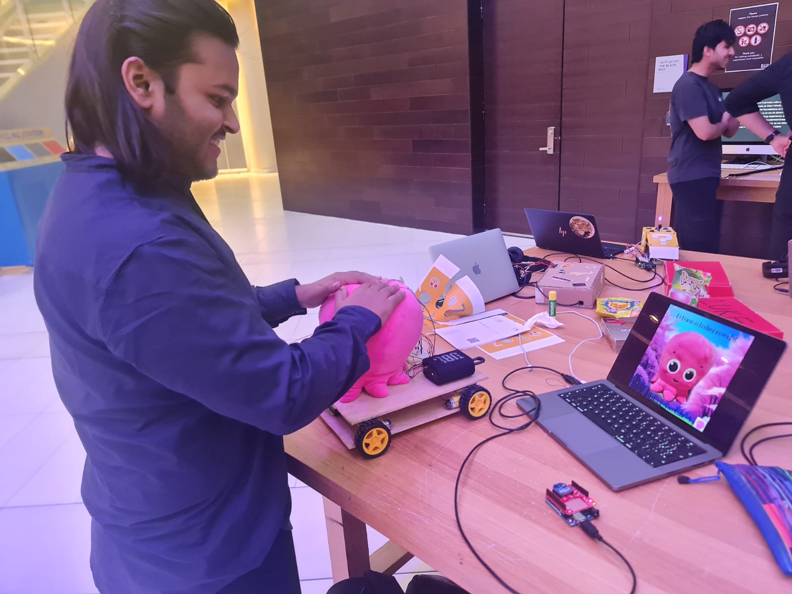
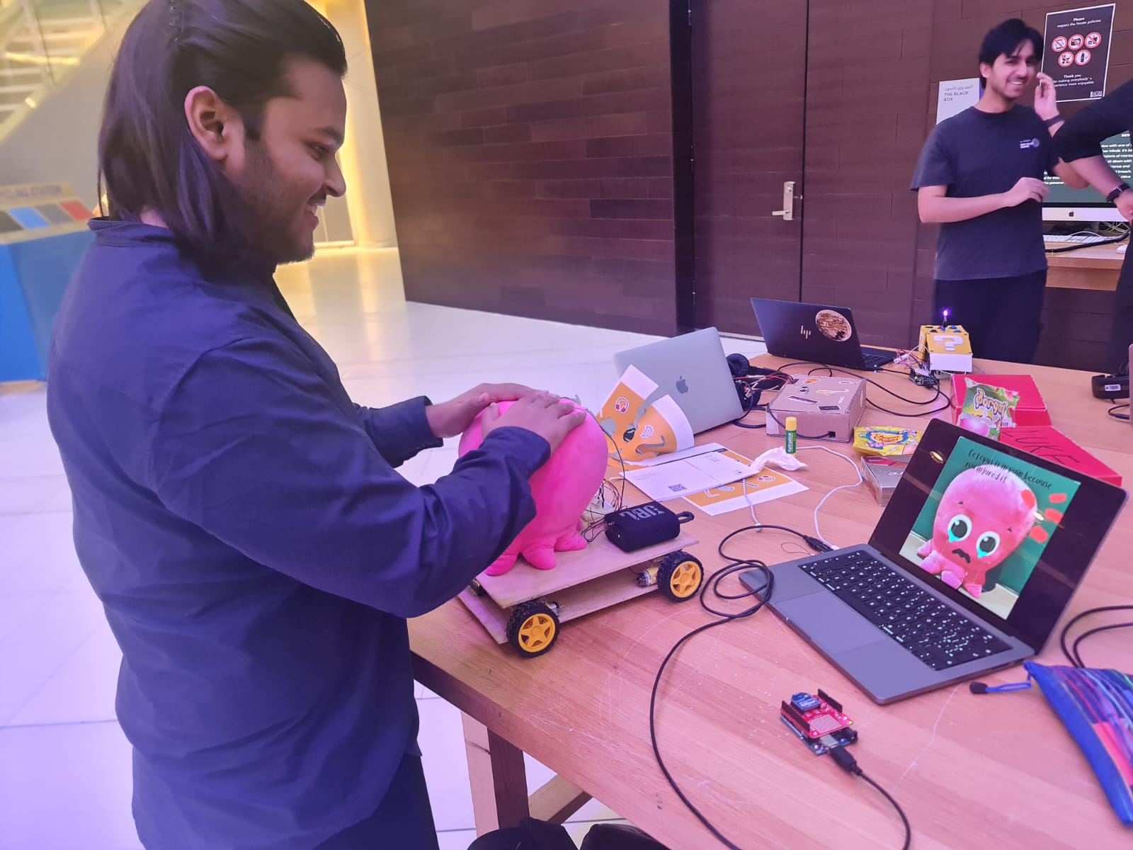
Interactive Mr Octopus is a wireless robot that is design to simulate a pet. It can be controlled using the arrow keys on a laptop. It has emotional states depending on its surrounding conditions and the digital version on the laptop responds according to the current emotional state of the Physical Robot. It also has sound interaction depending on its current emotional state. The project was inspired by a quest to create something fun and challenging to simulate a moving robot that has emotions.
I also had an Instruction sheet for the IM Showcase in addition to the onscreen instructions on p5. This was because I observed that very few people would actually read the instructions in the beginning. A good way to make them read was to make them tangible by putting them on a piece of paper which somehow enhanced their ‘influence’ . Here is an image of the Instruction Sheet :
Here’s a Demonstration video from the IM Showcase:
Inspiration
This started off as a joke. Literally . My friends and I had won a plushy at a game store in Dubai and we joked about how it would be so cool if I could make it move and give character to it. It sounded like a crazy and cute idea. So, I said – why not? I wanted to make something ambitious for my final project that would move wirelessly. I had initially considered a giant plushy of a Pokemon character- JigglyPuff – but realized that it was too big and I would need something smaller. So, I changed my concept to using an Octopus plushy and decided to give character and emotions to it .
I had borrowed and tried and tested lots of different sensors and modules from the IM Lab before deciding what to do and which ones to use.
19 BOOKINGS !! However, these gave me a very good idea of the resources available and how I could use them.
Most of the sensors were unreliable on a moving object and so I just used two types of sensors. Experimenting with the modules gave me an idea of how to set up wireless communication.
Concept and Interaction Design
The project consists of two main interfaces :
The Mr Octopus Robot is capable of moving forward, left, right and backward. It houses the main Octopus plushy and the movement system (using motors). A Piezosensor on top of its head is capable of detecting touch and classifies the types of touch as – (1)no touch , (2) light pat , (3) hit/pinch/ squeeze . A Photosensor senses the lighting conditions and classifies them into (1) low light(dark) , (2) medium(normal) light , (3) bright light . The emotional state of the robot is decided based on a combination of inputs from these two sensors. Since each sensor has 3 inputs each , the Octopus has a total of 9 unique emotional states.
The Project also has a p5 interface that allows the user to control the Mr Octopus Robot . The user can also play audio through the p5 interface depending upon the environment that the robot is in . The p5 interface receives the emotional state from the robot and displays a sketch/plays audio accordingly.
The bidirectional communication between the p5 interface and the Octopus Robot is enabled by 2 Arduinos and 2 XBee modules. The overall project is a unique, and fun to interact with robot that simulates emotions- making it an exciting project for anyone interested in robots that have emotions or are interactive.
Implementation
Hardware
Construction
I wanted to build my robot by using 2 layers of wood. The bottom layer of wood has the Arduino for the robot , the motors , power supply and a breadboard with the motor drivers.
The top layer of wood has an Octopus plushy , Piezosensor , Photosensor, A Bluetooth speaker and a breadboard . The breadboard is connected to the main Arduino Uno through jumper wires that pass through holes drilled into the top layer.
The whole structure- that is the two layers are held together by means of velcro and folded cardboard on top of the motors .
I used the method of testing each small part of the project separately and perfecting it before integrating everything together
Below, I have given details of the steps involved in construction of the robot :
Choosing Chassis material
I used thin plywood that I was able to get from the scene shop. I drew an outline of my Octopus plushy on the plywood to get a sense of scale and left extra space for breadboard and any additional components that I would need to add in the future , then I cut two rectangles of equal size using a handsaw (Each one would form a layer of the Chassis). The scale of the framework was much bigger than the usual size of a remote-controlled robot because I needed space for the Octopus plushy on top.
Making the Lower level
I unit-tested the motors first . Since I needed four wheels, I connected two motors in parallel to each side of the motor driver. Then I wrote test code for movement, and taped the motors temporarily on their correct places to see if they work properly.
Once everything worked, I glued the motors to the lower level using glue gun. However, after sometime I noticed that the glue gun didn’t work well in some areas of the wood and the motors would easily come out. So, I used super glue to stick two of my 4 motors on the lower level.
Making The Upper Level.
The upper level would just contain the plushy and a breadboard for the photosensor and piezosensor connections (the photosensor would have to be at the top to detect light).
Since the Arduino Uno was on the lower level, I would need some way of connecting wires on upper level with the lower level. I measured the diameter of the jumper wires and drilled 6 holes into the upper layer above the place where the Arduino was on the lower level to allow the wires to pass through. The diameter of the holes was just smaller than the jumper wires so that the ends could be held in their place . Thus, The wires didn’t pass but just the metal ends passed through.
There was another issue. The Arduino that I used in the lower layer would be taller than usual because I would have to use an XBee shield for wireless communication. There would also have to be enough space between the two layers to allow the wires to connect. This meant that I could not just stick the top layer on top of the motors directly , rather I needed some sort of padding in between to increase the height between the tp and the bottom layers.
For this purpose, I cut strips of cardboard, folded them , stuck each fold with glue gun to use as padding. One end of the cardboard padding would be attached to the motor via velcro and the other end would be attached to the top layer via velcro. Below is an image showing this: Velcro on top layer
The use of velcro was vital as this allowed me to take the top layer off whenever I wanted.
Testing Sensors
Once the motors were working , it was now time to test the sensors . For this, I used a separate breadboard and Arduino and wrote some test code to test some values and print them out on the Serial monitor to check whether the sensors were working correctly and test their range as well as the circuit connections.
The above image is of me testing a sound sensor and a photosensor. Although I spent a lot of time in testing and figuring out how to use the sound sensor, I decided not to include it in my final project as it was very unreliable and picked up small vibrations as sound too.
Eventually, I decided to use a piezosensor for sensing pressure on the plushy and referred to this circuit diagram – Piezosensor Circuit Diagram
Here, they recommended a 1 MegaOhm resistor but for my case , I found out that 330 Ohm resistor worked well and gave good decently spaced out values . I had some confusion while referring to the above diagram so I made the connection of the piezosensor as a classic voltage divider circuit that we studied in class. I made test code to log the values of the sensor to see how sensitive it was and what values it gave when pressed with various degrees of force.
NOTE: (For anyone trying to do this in the future), the hardest part of using the piezosensor(surprisingly) was soldering metal on the outer ring. (Please try to find an already soldered sensor) . What happens is that you have to wait for the whole sensor to get hot enough to melt the solder and this takes a very long time. I successfully soldered one sensor but then the solder came out after some time. Then, I tried with another one and the sensor broke when I applied excessive force. Eventually , everything worked fine with the third one and I was able to use that in my final project.
Integrating Power
Since I had everything on the robot running wirelessly, I needed to integrate power . Initially I had just supplied 6V to the Arduino on the robot thinking that it would be enough to power both the Arduino as well as the motors. However, it turned out that 6V was not enough to run the whole thing. So, I used a separate 6V power supply for the motors by powering the Vm pin of the motor driver with it . Even then the motors were not running at full speed. I checked the documentation for the motors and was surprised to learn that EACH MOTOR required power of 4.5 Volts to run properly which made the total power requirement 18 Volts to run the entire system properly.
However, I was supplying only 6 Volts which is a third of what is required. Despite this, At maximum speed, the motors would work and the whole robot would move at a decent pace . Also, since I did not want the robot to go too fast, this was fine as long as I ensured that the batteries were replaced frequently.
Each 6V supply consisted of 4 AA batteries connected in series. The Arduino was powered through the jack. One thing I noticed was that the motors consumed a lot of power and I had to replace the batteries for the motors quite frequently. I realized that if the batteries drained even a little bit, the Voltage they would supply would go below 5 Volts and would not be enough to run the motor properly. I had tried replacing 6V supply with a 9V battery but after consulting with Professor Shiloh , I realized that the internal resistance of a single 9V battery meant that it supplied LESS current than 4 AA batteries connected in series. So, I stuck with the 6V power supply.
I arranged the cells in a battery connector from consumables .
Putting everything together (Final Integration)
This step involved sticking everything to the wooden frame at the appropriate place. For the lower level, I kept the breadboard in the center, The Arduino close to one of the edges (so that I could access its port and change code when I wanted) , and the power supply close to the Arduino (so that I could easily plug and unplug it) . For the upper layer, I arranged the plushy to the front of the board , and kept the wireless speaker and breadboard at the back. For sticking the breadboards, I just peeled the sticker at the back . The upper layer was easily joined using the velcro with cardboard padding described earlier.
I placed the plushy on top , soldered some wires and put the piezosensor on top of it .The wires are held in place by tape.
I am using an XBee module for wireless communication. An XBee module uses radio communication . The special thing about these modules is that once configured, they can send and receive data AT THE SAME TIME. The AT THE SAME TIME part is very important as a standard radio module like NRF24L01 is not capable of this. In such modules, you will have to write code to have it receive and send data at different times. However, XBees save us from this hassle. Here is the link to the wireless kit by sparkfun – https://www.sparkfun.com/products/15936 (All components of this kit are available in the IM Lab booking system as of May 2024). The Board along with the shield looks like this : Arduino Board with XBee Shield and XBee Transmitter
I had an Arduino connected to my laptop with an XBee module – say XBee1 mounted on top with an Xbee Shield. I had another arduino on the main robot with another XBee module – say XBee2 mounted on top with another Xbee Shield.
What this does is it basically allows the two XBees to communicate with one another via radio communication.
My communication network then is as follows:
p5 <-> Arduino for communication <-> XBee1 <-> XBee2 <->Arduino on Robot
The communication is bidirectional at every step. It is a 5 step bidirectional communication.
XBee1 takes information from Arduino_for_communication and forwards it to XBee2. At the same time , it listens for data from XBee2.
Similarly, XBee2 takes information from Arduino_main_robot and forwards it to XBee1. At the same time , it listens for data from XBee1.
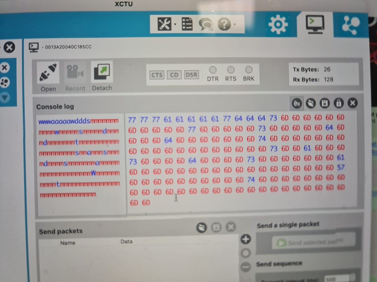
I included the <SoftwareSerial.h> library for interfacing with the XBee’s . Initially I had tested their communication and configuration and tried sending messages through XCTU which worked quite well. XCTU provided me a way to debug by seeing what messages were sent and received by the XBee.
The software consists of the p5 sketch , and two sketches for each of the arduinos . The arduino connected to the computer is called Arduino_for_comms and the one on the main robot is called Arduino_main_robot.
Arduino_for_comms reads data from p5 and forwards it to the XBee module . The XBee module on Arduino_main_robot reads this and forwards it to the arduino on the main robot. At the same time, Arduino_for_comms reads the data from XBee module and forwards it to the p5 sketch.
Arduino_main_robot reads data from the XBee module and carries out movement action according to it. At the same time, it also send data to the XBee module which forwards it to Arduino_for_comms.
One key thing to note is that Arduino to p5 communication and Arduino to Sensor communication relies on Integers , However XBee to XBee communication relies on characters. I thus needed an effective way to switch between these two data types. Neglecting this initially caused a lot of complications that are lengthy to be explained here and took a lot of time to debug but it all boils down to using the right data type.
Software side for Arduino
As mentioned, there were two Arduinos and thus two Arduino codes. The link to both of the .ino files is here :
Listens for data from p5 sketch and sends any data it hears to the XBee module – which then forwards it to the Xbee on Arduino_main_robot . At the same time it listens to data from the Xbee module mounted on top and sends it out to the p5 sketch.
Listens for data from sensors – combines it to output a character and sends it to the XBee module – which then forwards it to the Xbee on Arduino_for_comms . At the same time it listens to data from the Xbee module mounted on top and moves the motors accordingly.
In addition, I had also used several Arduino sketches for unit testing motors, sensors and communication . The following is a link to these sketches :
To check and test, run it on Chrome , setup the serial , and you can change Val1 in the code to switch the sketch, press option to play introduction sound when sketch is happy and shift to play sound according to the emotional state
Description of emotional states of the robot
The p5 sketch changes according to the environment or emotional state of the robot. The robot has the following emotional states:
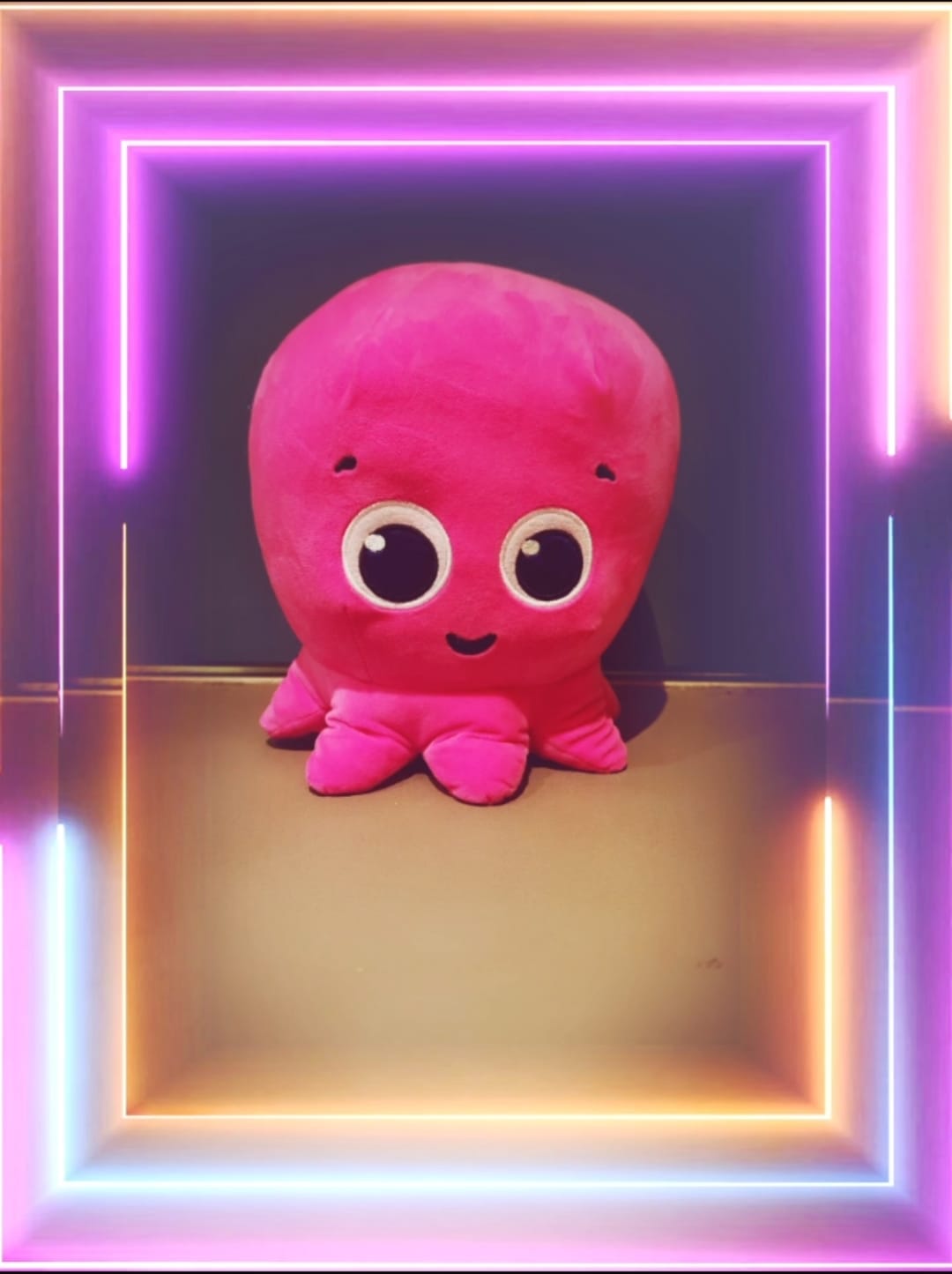
Peaceful (Normal light , no touch)
Vibing in the light (High light, no touch)
Sadness in the dark (Low light, no touch)
Loved normal (Normal light, Gentle touch)
Loved Bright (Bright light, Gentle touch)
Loved Dark (Low light, Gentle touch)
Hurt normal (Normal light, Hit/pinch)
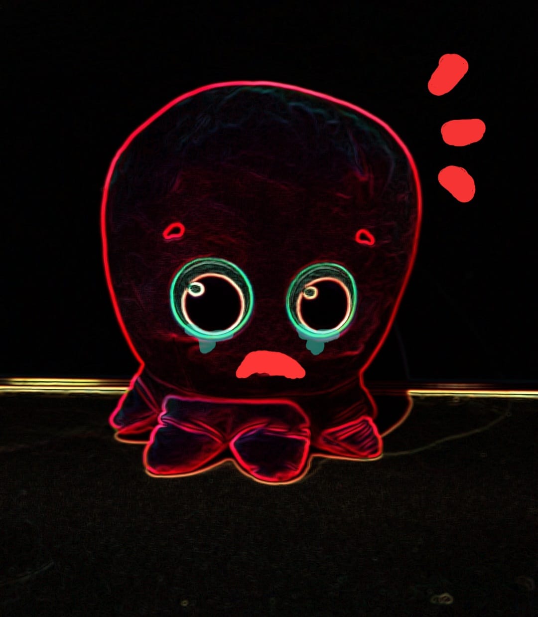
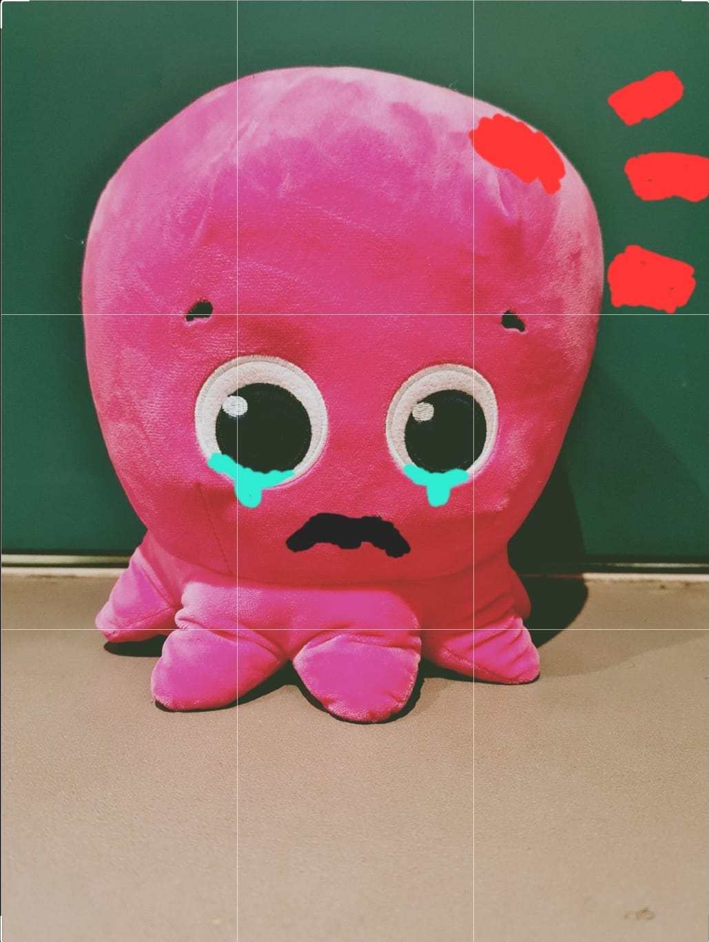
Hurt dark (Low light, Hurt/pinch)
Hurt Bright (Bright light,Hurt/pinch)
The p5 sketch changes according to the emotional states of the robot . These states are determined by the following readings from the piezo sensor and photosensor ( I tweaked them a little to adjust for light in the arts center).
For Piezosensor :
>= 70 is counted as a hit
>20 and <70 is counted as a pat
<20 is counted as no touch
For Photosensor :
>900 is counted as bright
<900 and >550 is counted as normal light
<550 is counted as dark .
Design elements
Visuals
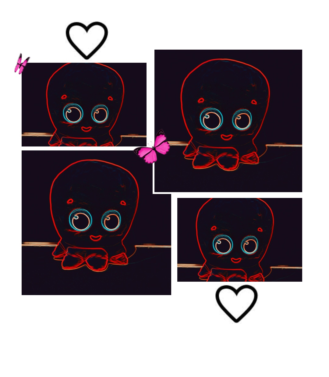
I have a different image for each of the emotional states. The images are listed below :
Octopus hit in darkOctopus hit in normal lightOctopus hit in bright lightOctopus normal in bright lightOctopus loved in darkOctopus loved in bright lightOctopus loved in normal lightOctopus peaceful – normal light and no touchOctopus sad in darkness – no light and no touch
Every Visual above was generated using a mixture of snapchat filters, the LUMI app . Some features were drawn by SPen on my mobile phone. Snapchat filters were very useful for the whole visual generating process.
Audio
I used the following audio files in my project :
Octopus Trimmed.mp3 – which is an audio that introduces the Octopus, it is a snippet of the following YouTube video : PinkFog Octopus hello
Peace_Trimmed.mp3 – This is the peaceful sound effect that I adapted from Kung Fu Panda.
Sad_Piano.mp3 – Sad sound sourced from Pixabay
Loved_music.mp3 – Calm soothing sound effect from Pixabay
Vibe_music.mp3 – Groovy sound effect from Pixabay.
The sounds are played according to the emotional state of the Octopus . The introduction sound can be played by pressing the (option) key when the octopus is in an emotional state that is NOT SAD.
Fonts
I have used the following Fonts in my project:
ArtFully Regular.ttf
Hartford.ttf
NoteToSelf – Regular.ttf
NoteWorthy Bold.ttf
Sportfield Varsity Stacked.ttf
Summary
Here’s a summary of all assets I have used (code snippet from p5):
The users reported that the sideways movement is a bit slow. I suspect this is due to the 6V power supplied for the motors instead of the 12V that they require (Each motor requires around 3V -> but I have supplied all 4 motors with 6 Volts) . This is fine as I do not want the robot to move too fast.
Initially I was using a click mechanism for playing sound but a user said that using the option key and the shift key would be much better so I decided to use these keys in addition to the click mechanism. This is also reflected in the Instructions sheet.
I don’t have any particular videos of User testing but I asked for advice from Lab assistants and other people working at the IM Lab. Here’s a video of a user testing movement and the introduction interaction
I realized the movement should be faster and the reason it wasn’t fast enough was because the batteries had drained and were supplying less voltage than usual so I just took the top off (which was easy since it is attached by velcro) and replaced the batteries.
IM Showcase
The Showcase went amazing!! People gave really good reviews and a lot of people enjoyed playing with the robot and interacting with it. At times , they would drive it over to random people and say hello. Several people said that the project was technically impressive and cute.
A lot of people took photos with and of my project . There is a slight issue though – I barely took any videos 🙁 – However, I do have some recordings of people trying it out and they are attached below :
I felt very happy watching people interact with it and really enjoyed watching them get surprised when trying out different interactions such as the introduction sound and pressing with force on the piezosensor(on the top of the Octopus) that triggers hurt sound and hurt image.
Potential Future Developments
This project could be potentially improved by :
Making a stronger frame or chassis that would enable the whole structure to move faster without risk of damage.
Integrate more sensors such as sound sensor and human presence sensor.
Play audio through a Music maker shield rather than using a bluetooth audio speaker.
Easier braking system – right now , because of the way the code and character conversion works the only way to brake is to press the down key followed by either left or right arrows. With a little bit more code editing and correct power for the motors, I could fix this and change the key binding for brake to something simpler such as a spacebar.
A system for autonomous movement
Challenges and Things learned
Heads up to anyone making something similar in the future- You have chosen an ambitious project !! The following are some challenges I faced that I can recall and how I fixed that . Hopefully, this can be of some help to you –
Integrating power – The DAGU motors we are given in the sparkfun kit need a power of 4.5 V EACH for optimal running. This sounds like a lot and it is a lot but be mindful that anything less than this and the motors may not function properly or may turn slower than expected. This is the issue I faced when the motors were not working correctly
Wireless Communication – Use XBees : People have used NRFL01 modules previously because they are cheaper and smaller but if XBees are available in the booking system , use them. The difference is that XBees can SEND and RECEIVE data at THE SAME TIME. Check out the sparkfun tutorial on setting them up and you should be fine . This is not possible for the NRF modules and it is a hassle to achieve wireless bidirectional communication with them (people have done it in the past , but it’s more difficult than just using XBee) . NOTE: XBee modules used pins 2 and 3 for Rf-Tf on Arduino UNO for communications so do NOT connect anything to these pins. I missed that and spent a lot of time debugging.
Use VELCRO: Lifesaver !! I could dismantle by whole project to replace new batteries or upload code to the Arduino or rewire connections because I had connected the layers with Velcro. Velcro is super super useful .
Soldering on a Piezosensor – Very difficult !! Try using a sensor that already has soldered wires. If not check the construction section of this documentation. I faced a lot of difficulty soldering them. Some are very sensitive and break if you apply too much pressure.
Playing Audio in p5 – Always set play mode to ‘restart’ if you are calling play() in loop . you can use setVolume() function to adjust the audio in your sketch (you have to include a library but this is very useful) .
Make Room for Recalibration- I ended up gluing my Arduino to a hard to reach place in the lowerlevel . This was a serious issue as I faced difficulty trying to reprogram it . Eventually, I was able to somehow sneak the connector in. If you are using light or infrared sensors, you will HAVE TO RECALIBRATE them while setting up as the lighting during showcase is different from lighting in IM lab . Be mindful of this and make sure you can recalibrate easily.
If using XBee, be mindful of the datatypes they can send and receive, use XCTU for debugging. I spent a lot of time debugging because I used the wrong datatype.
Try to reuse the starter code given by professor and adapt it accordingly – it’s way easier than writing from scratch which is what I tried doing initially.
Reflections (Proud Of !!)
When I had selected this topic , I knew it was a fun challenging project to work on. Looking at past documentation, I realized that very few students had implemented bidirectional wireless communication before and this is generally difficult to implement. I spent several days trying to configure my XBees and setting the power for my project correctly. Then , I spent several hours trying to figure out how to convert between appropriate datatypes for the 5 way communication. at one point, I thought that I wouldn’t be able to complete on time .
Despite that I was able to not only set up bidirectional wireless communication, but was also able to create a great design for the p5 sketch which I am really proud of . The project at the end turned out better than my expectations and the positive reviews and appreciation from Professors and Students at the IM Showcase made me very happy !!
There were lots of things I had to learn on my own for this project – from setting up XBees, to integrating power, soldering wires the right way, testing several sensors, making a chassis, using a piezosensor- It was a great experience. At the end , I was able to deliver on the high expectations I had for myself for the final project and I am very proud of that .
Special Thanks to ……
I would like to Thank the following people . This project wouldn’t be possible without their help, support and guidance-
Professor Aya Riad for teaching the course, following through with my project, encouraging me to make innovative projects , and helping me with ideas.
Professor Michael Shiloh for help with debugging and testing the motors +help with soldering on the piezosensors.
Stefania and Ume for their help with using IM equipment and support .
All the Lab Assistants – Basil , Khadijah , Ramsha, Raya, Aadhar, Moeez, Dania, Arslan, Aya for helping and assisting me in my project as well as dealing with all of my check ins and check outs .
Sanansh Garg for allowing me to kidnap his Octopus Plushy and for User testing.
Swostik Pati and Sri Pranav Srivatsavai for guidance on how to set up bidirectional communication , for their amazing documentation – and for starting the joke to put a Jigglypuff on top of a car.
Nikhil Mundra for the mini JBL Speaker that made wireless audio possible.
All of my Classmates across all sections especially in mine.
Everyone who came to the IM Showcase .
Everyone else who helped me , provided support and kept company . It was a pleasure working with you all !!
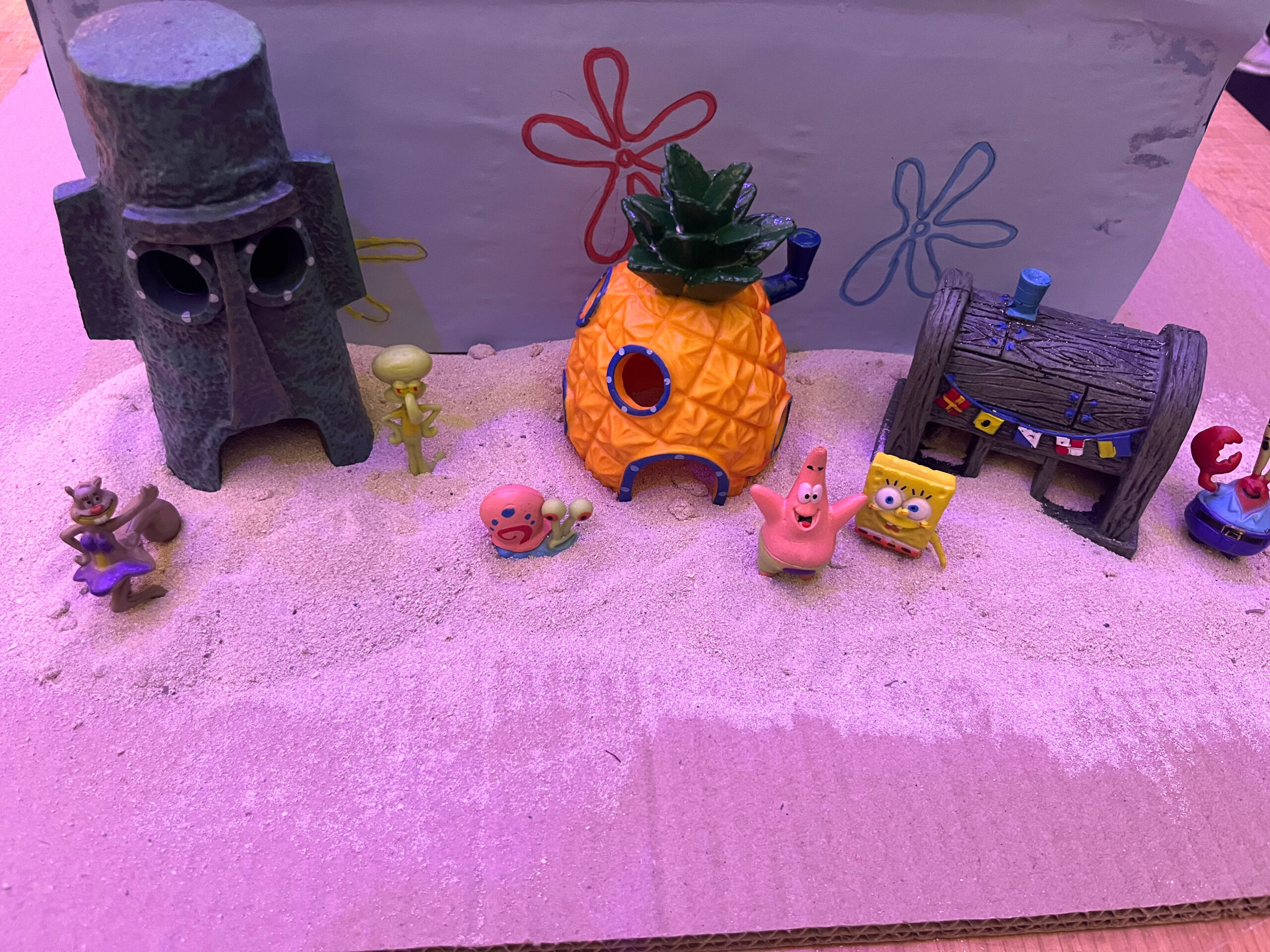
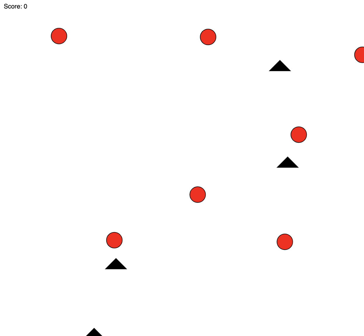
When I look at how F1 drivers train their reflexes, one of the machines inspired me to create this game. However, this game is not to train your reflexes but your memory. Inspired by this, my project, “SpongBlob” aims to enhance users’ color memory skills through an interactive game developed using Arduino and p5.js. This game not only serves as an entertaining experience but also as an educational tool to study color perception and memory. The game is also aimed for kids who are at risk of losing their focus span to the developing social media and short video world, which makes this game a tool for them to gain their focus back. This inspired the SpongeBob theme, so that it is more kid friendly.
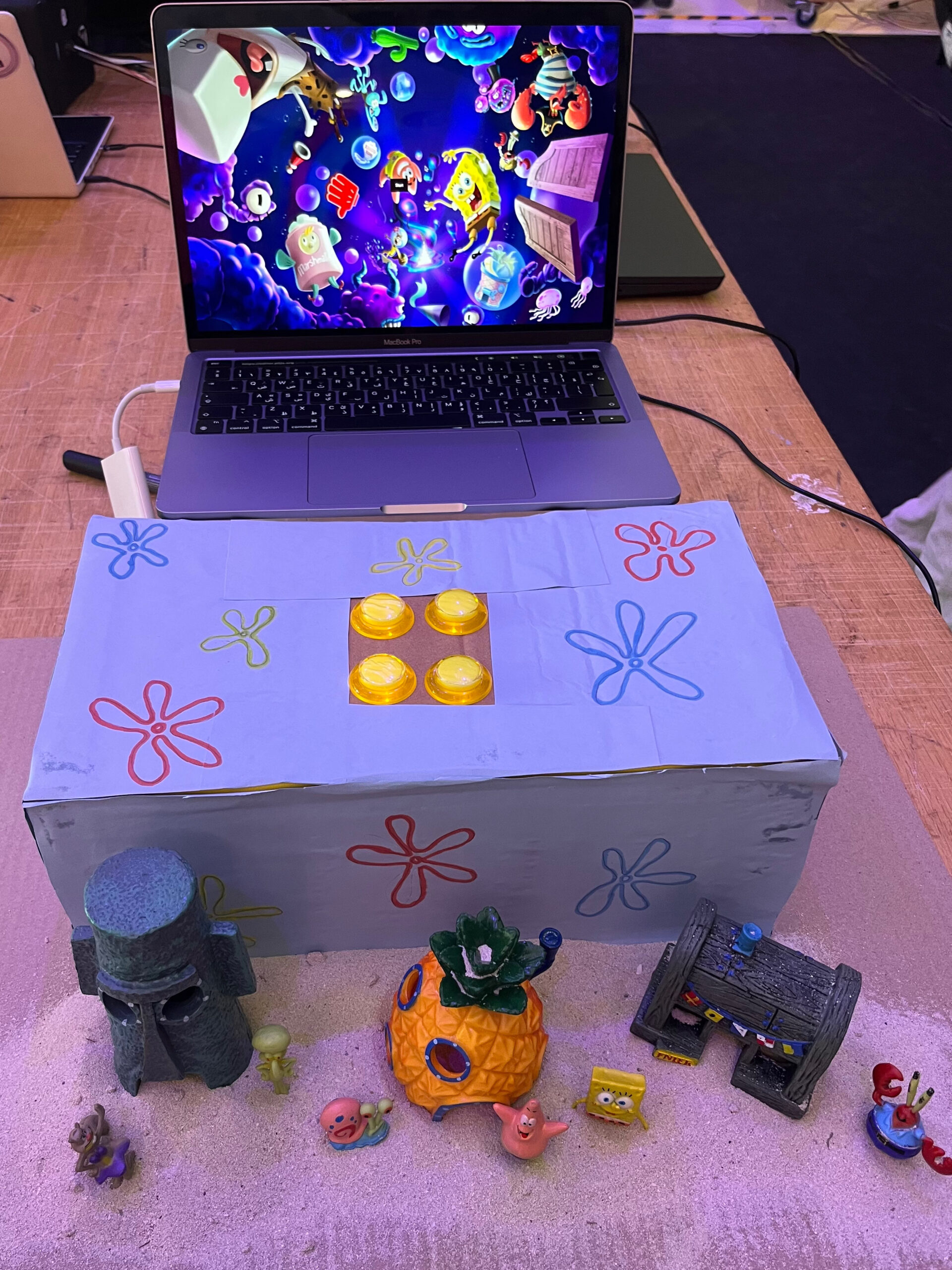
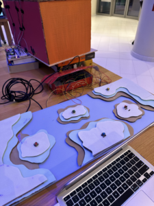
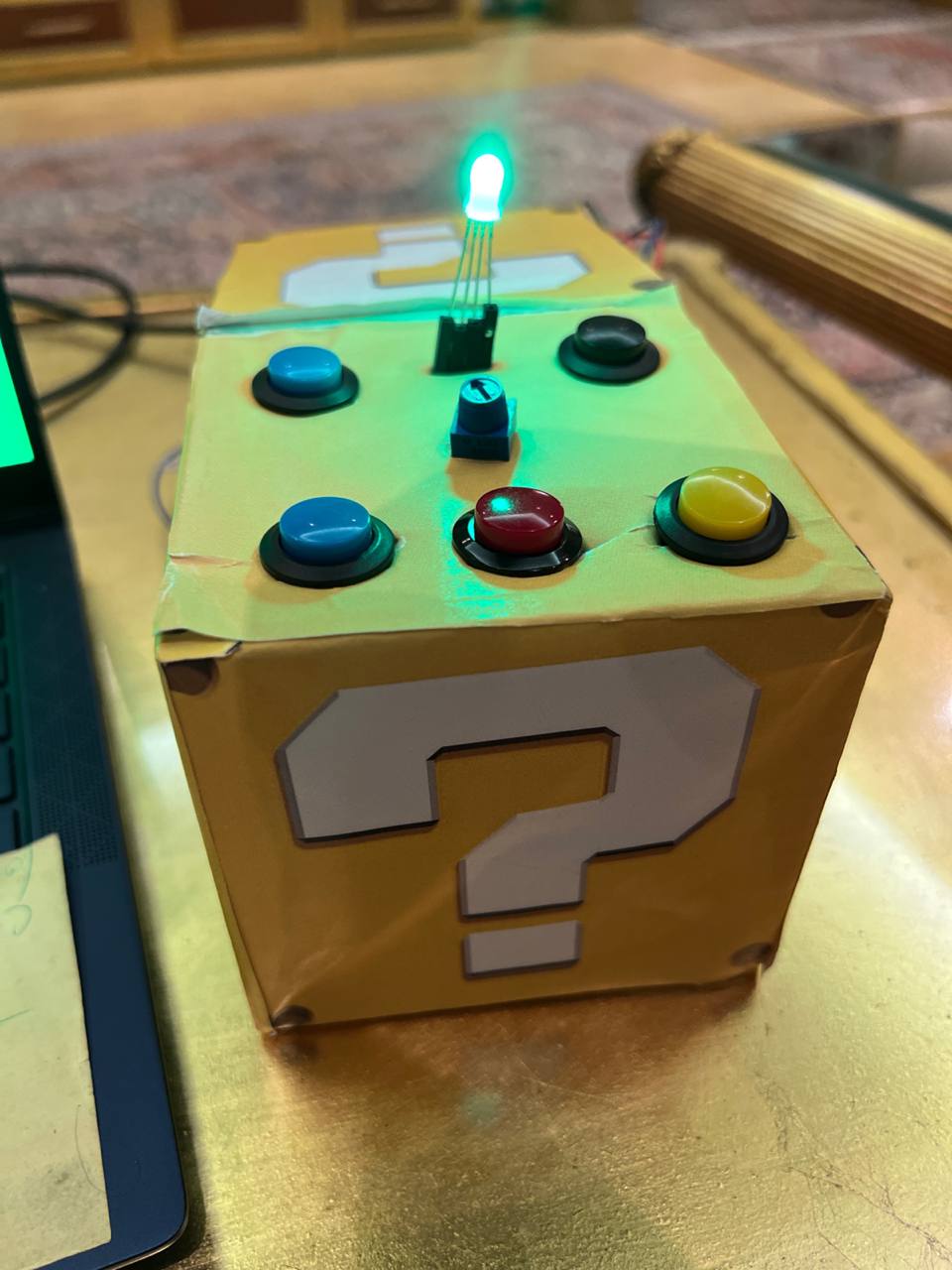
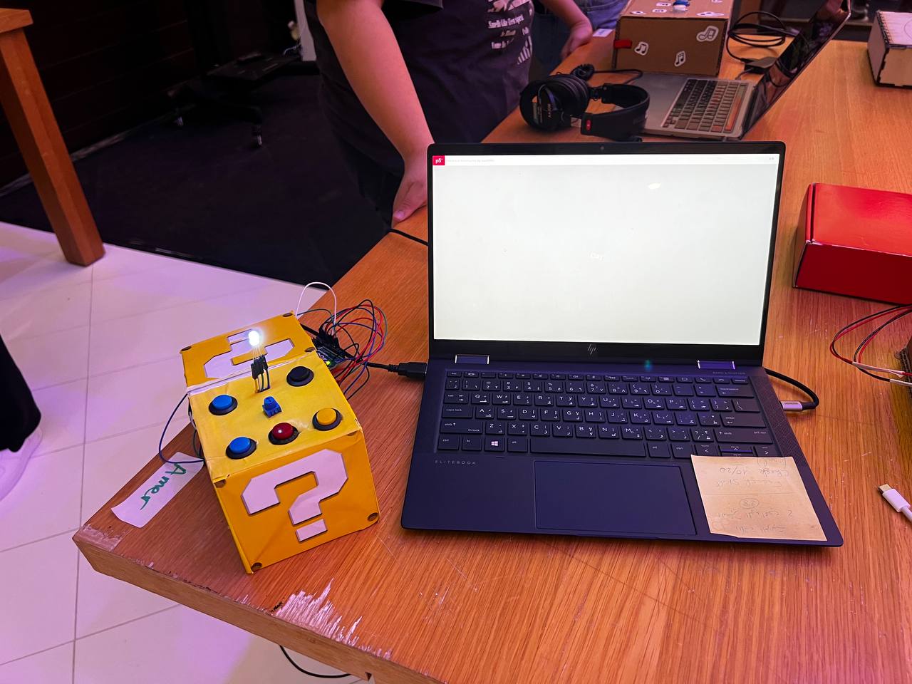
Game setup:
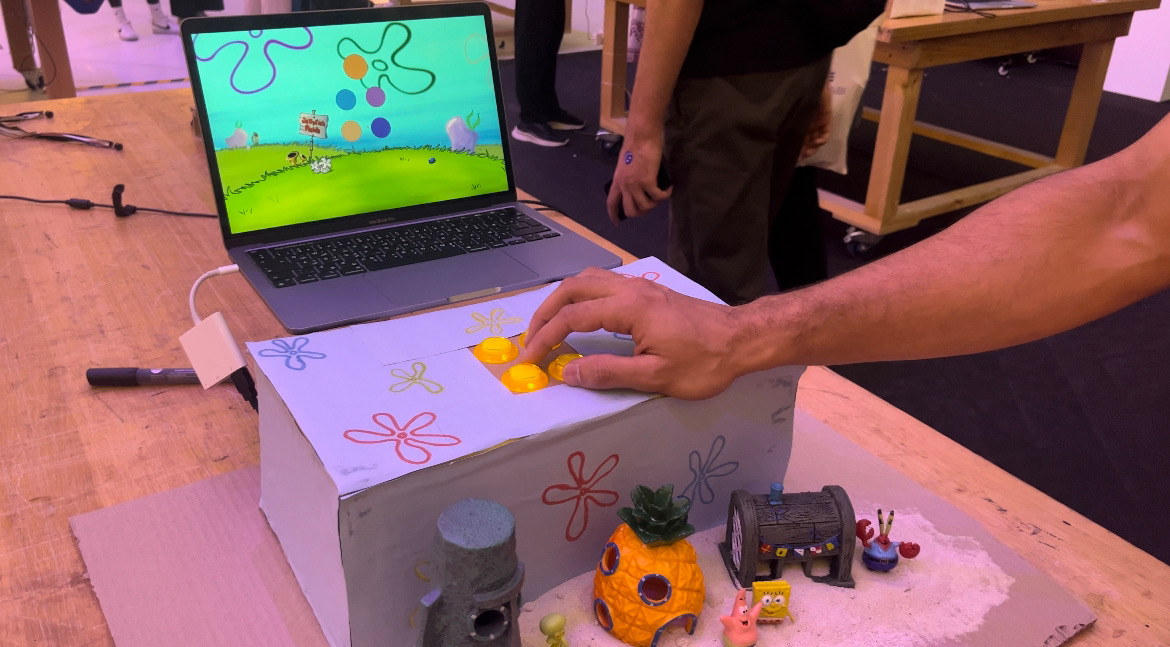
The game has an interactive set up with 4 buttons replacing the keys on the keyboard. By pressing the buttons, the players are interacting with the game on the P5 sketch. This is shown in the following pictures:
As shown in the picture, the aesthetics of the game are really important especially since this game is also targeting kids. Having a nice set up of “Bikini Bottom” was really important in my opinion to make sure that the game is not just functioning well but also looks appealing to the players.
The use of these buttons makes it so much easier than the keyboard according to the users that tested the game. Moreover, when user testing, most of the students suggested having a less hectic and messy background so that the player can focus and memorize the colors of the circles without getting distracted by the background. There was some debate over whether the users should get to see the score they achieved or not. Since it is a memory game, I thought the players should focus more on memorizing and enhancing their focus span than focus on the score, so I did not make it visible to the players.
// Define pin numbers for buttons
const int leftButtonPin = 2;
const int upButtonPin = 3;
const int downButtonPin = 4;
const int rightButtonPin = 5;

void setup() {
  Serial.begin(9600);
  // Set button pins as inputs
  pinMode(leftButtonPin, INPUT);
  pinMode(upButtonPin, INPUT);
  pinMode(downButtonPin, INPUT);
  pinMode(rightButtonPin, INPUT);
}

void loop() {
  // Read button states and send data over serial
  int leftButton = digitalRead(leftButtonPin);
  int upButton = digitalRead(upButtonPin);
  int downButton = digitalRead(downButtonPin);
  int rightButton = digitalRead(rightButtonPin);

  // Send button states to serial
  Serial.print(leftButton);
  Serial.print(",");
  Serial.print(upButton);
  Serial.print(",");
  Serial.print(downButton);
  Serial.print(",");
  Serial.println(rightButton);

  // Delay to control the rate of data transmission
  delay(100);
}
This Arduino sketch manages four buttons connected to the board, using pins 2, 3, 4, and 5 for left, up, down, and right buttons respectively. The setup() function initializes serial communication at 9600 baud and sets the button pins to input mode. The loop() function continuously reads the state of each button using digitalRead() and sends these states over the serial connection using Serial.print(). Each button state is outputted sequentially and separated by commas, with a newline at the end of each set via Serial.println(). A delay(100) is included to control the rate of data transmission, preventing data overflow and ensuring manageable communication speeds.
function drawGamePage() {
  //song.play();
  background(backgroundImage);
  if (currentPage == 2 || currentPage == 3) {
    let selected = -1;

    // Map arrow keys to grid positions
    if (ArrowUp == 1 && ButtonPressed == 0) {
      selected = 0; // Top-left
      ButtonPressed = 1;
    } else if (ArrowDown == 1 && ButtonPressed == 0) {
      selected = 1;
      ButtonPressed = 1; // Top-right
    } else if (ArrowRight == 1 && ButtonPressed == 0) {
      selected = 2;
      ButtonPressed = 1; // Bottom-left
    } else if (ArrowLeft == 1 && ButtonPressed == 0) {
      selected = 3;
      ButtonPressed = 1; // Bottom-right
    } else if (
      ArrowLeft == 0 &&
      ArrowRight == 0 &&
      ArrowUp == 0 &&
      ArrowDown == 0
    ) {
      ButtonPressed = 0;
    }

    // Check if the selected color matches the currentColor
    if (selected != -1) {
      if (gridColors[selected] == currentColor) {
        prepareNextLevel();
      } else {
        currentPage = -1;
      }
    }
  }

  fill(nextColor);
  ellipse(windowWidth / 2, 200, 120, 120);
  let padding1 = windowWidth / 2 - 75;
  let padding2 = windowHeight / 2 - 100;
  for (let i = 0; i < gridSize; i++) {
    for (let j = 0; j < gridSize; j++) {
      fill(gridColors[i * gridSize + j]);
      ellipse(
        padding1 + j * (ellipseSize + 50),
        padding2 + i * (ellipseSize + 50),
        ellipseSize,
        ellipseSize
      );
    }
  }
}

function drawOverPage() {
  //laugh.play();
  background(gameOverImage);
  textAlign(CENTER, CENTER);
  textSize(32);
  fill(0);
  text("Game Over", width / 2, height / 2 - 100);

  // Draw "Again" button
  fill(200); // Light grey button background
  rect(width / 2 - 100, height / 2, 200, 50);
  fill(0); // Black text
  text("Again", width / 2, height / 2 + 25);

  // Draw "Home" button
  fill(200); // Light grey button background
  rect(width / 2 - 100, height / 2 + 70, 200, 50);
  fill(0); // Black text
  text("Home", width / 2, height / 2 + 95);
}

function drawInstructionPage() {
  //song.play();
  background(instructionsImage);
  fill(0);
  textSize(24);
  textAlign(LEFT, LEFT);
  text("Instructions", width - 810, height - 710);
  textSize(16);
  text("Welcome to the Memory Game! Here's how to play:", width - 840, height - 655);
  text("1. Memorize the colors shown on top of the screen.", width - 840, height - 625);
  text("2. Use the buttons to select the correct color from the grid.", width - 840, height - 595);
  text("3. Match the colors correctly to advance to the next level.", width - 840, height - 565);
  text("Press Space Bar to select Serial Port", width - 840, height - 535);
  textAlign(CENTER, CENTER);
  rect(width - 780, height / 2 - 40, 80, 40);
  fill(200);
  text("Continue", width - 740, height / 2 - 20);
}


function draw() {
  background(220);
  if (!serialActive) {
    text("Press Space Bar to select Serial Port", 20, 30);
  } else {
    text("Connected", 20, 30);
  }

  if (currentPage == 0) {
    drawStartPage();
  } else if (currentPage == 1) {
    drawInstructionPage();
  } else if (currentPage == 2) {
    drawFirstPage();
  } else if (currentPage == 3) {
    drawGamePage();
  } else if (currentPage == -1) {
    drawOverPage();
  }
}
The P5 sketch code is maily about the game page which has the conditions that make the game more interesting. The drawGamePage() function in this p5.js code is designed for a memory game, where it handles the game logic and user interactions during gameplay. It first sets the background and checks if the game is on specific pages (like a game level). The function maps arrow key inputs to grid selections, managing state with a ButtonPressed flag to avoid repeated selections. If a selected color from the grid matches a target color (currentColor), the game progresses to the next level; otherwise, it switches to a game over page. It dynamically renders colored ellipses on a grid, representing game elements. Additionally, other functions like drawOverPage() handle the game over screen, displaying buttons for restarting or returning to the home screen, and drawInstructionPage() displays the game instructions. The main draw() function coordinates these pages based on the current game state, updating the display and handling transitions between different parts of the game, such as starting, instructions, gameplay, and game over scenarios.
Aspects of the project I am proud of:
Game Logic Implementation: The effective mapping of user inputs (arrow keys) to game actions and the incorporation of game state management ensures that the gameplay is both challenging and engaging.
Serial Communication: The use of serial communication to connect Arduino inputs to the p5.js game logic demonstrates a robust application of cross-platform communication techniques, vital for interactive media projects.
Areas for Future Improvement:
Complexity and Features: Introducing additional levels of difficulty, more complex game mechanics, or multiplayer capabilities could increase the game’s replay value and appeal to a broader audience. Also having new shapes, characters to memorize and not just the circles can be fun!
Extensive Testing and Debugging: Conducting more thorough testing across different platforms and setups could identify and resolve any existing bugs or issues with user interactions, ensuring a smooth and reliable user experience.
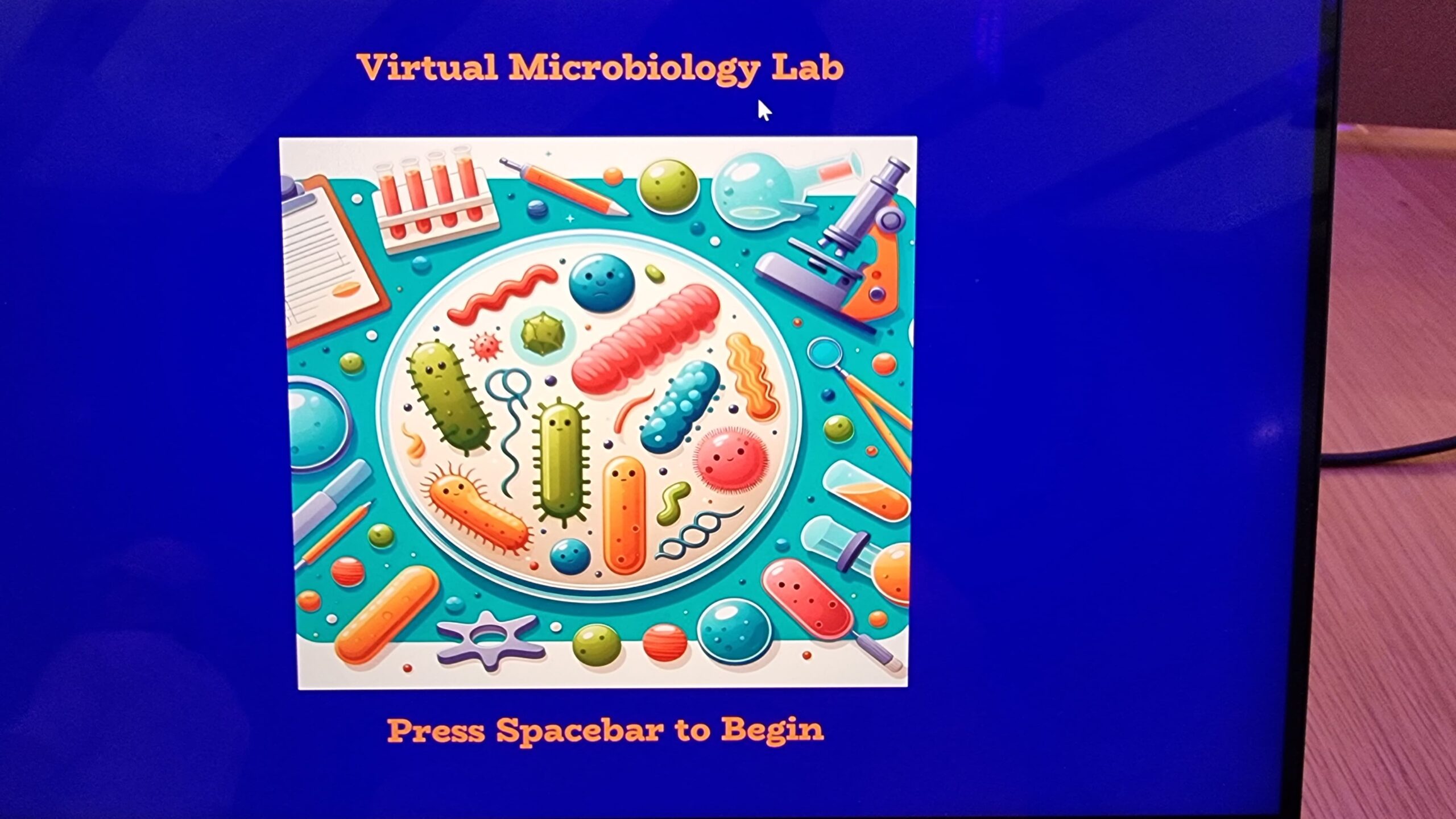
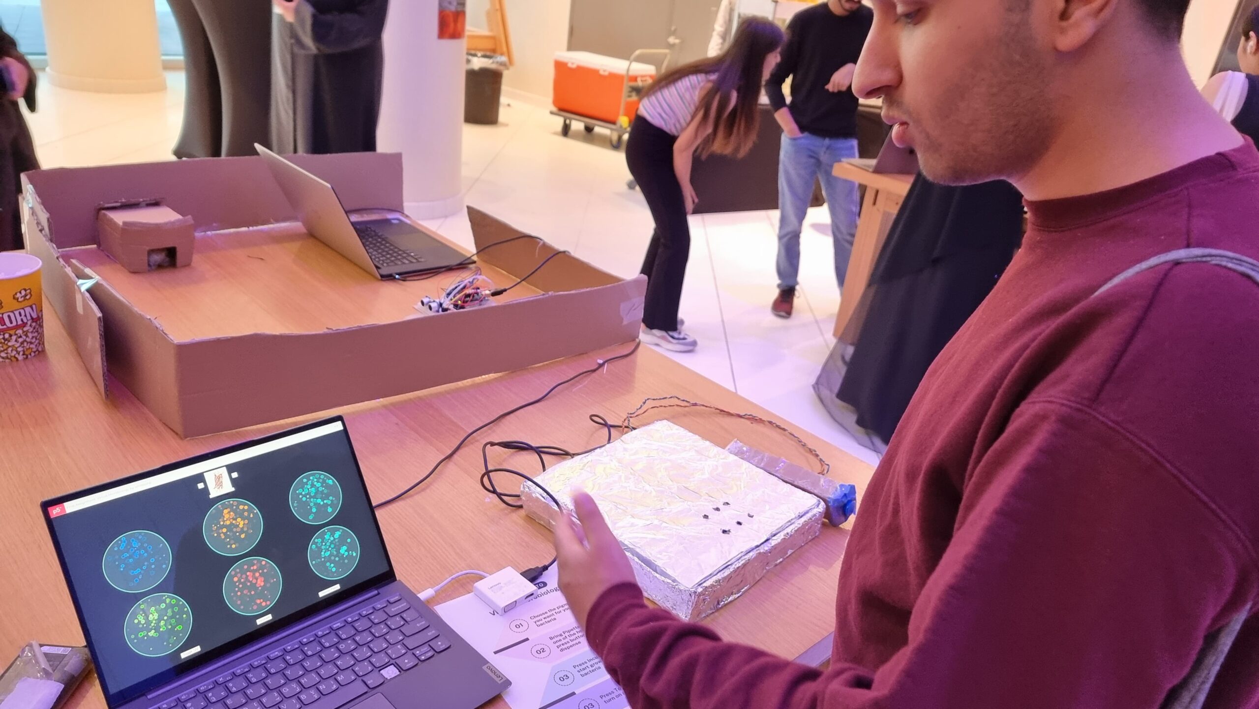
Throughout the semester, I’ve created projects that, in a sense, gamified concepts in Biology. Back when I worked on my Assignment 2, I had expressed a desire to allow users to select multiple color options for the bacteria. So, this project grew out of that desire, in addition to giving people a chance to practice very basic Synthetic Biology / Microbiology.
In essence the concept is simple. There are six prepared agar plates. Additionally, there are six fluorescent proteins: Green Fluorescent Protein [green], mCherry [pinkish-red], mOrange [orange], mKO [yellow], mCerulean [cyan], and Blue Fluorescent Protein [BFP]. All of these proteins fluoresce naturally under UV light and are not usually produced by bacteria. Instead, they are obtained from bioluminescent animals and can thus be used as a method to verify whether a certain gene editing technique worked in bacteria. But that biology-heavy introduction aside, the idea was that users select the fluorescent protein-modified bacteria they want and “pipette” them into the corresponding plate. Then, they can incubate the bacteria to watch them grow and toggle the UV light to actually see the fluorescence.
Implementation
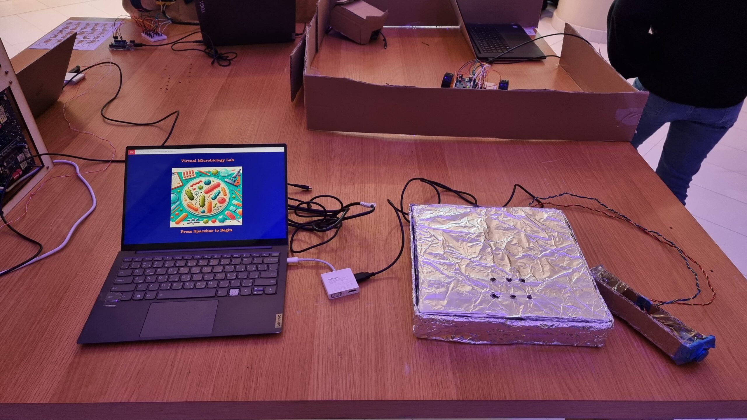
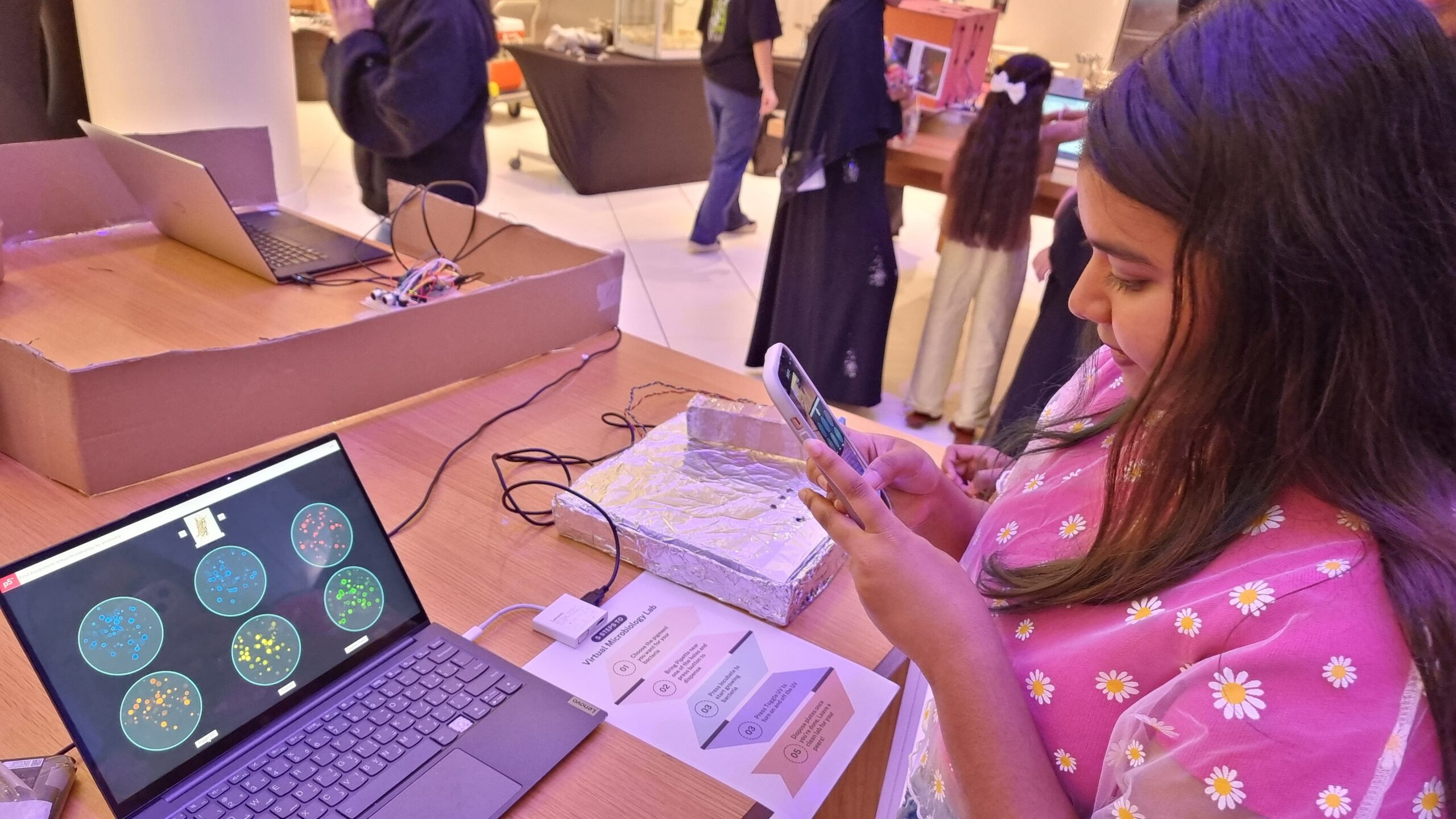
Interaction Design
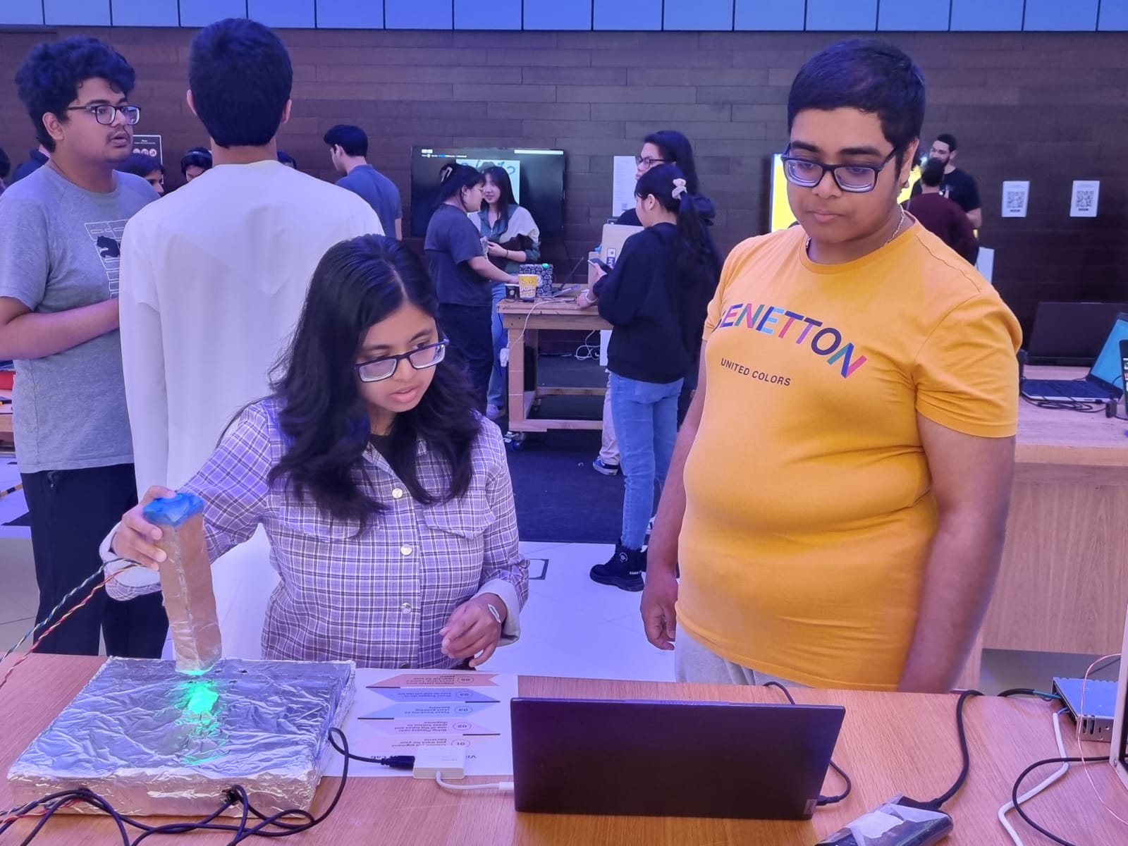
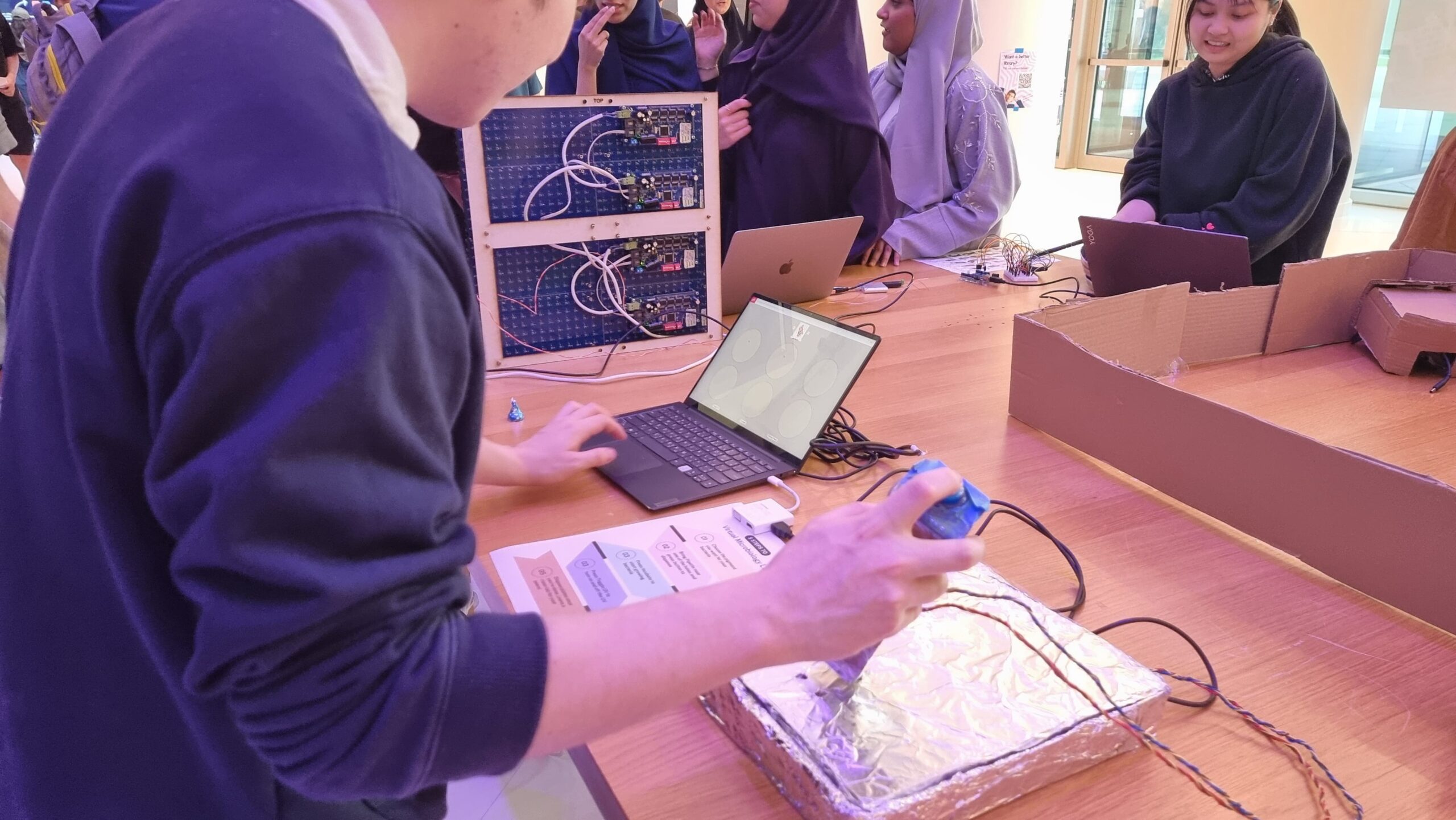
As mentioned above, the interaction design has two main parts: the laptop-focused part, and the physical prototype part. On the laptop, the user can press on-screen buttons to change the fluorescent protein, incubate the bacteria already plated, toggle the UV lamp, and dispose of the plates. On the physical prototype, the user has to bring the pipette to one of six holes (each of which contains a hidden photoresistor) and press a button to “dispense” bacteria. The idea is that the user controls which color of bacteria they want to grow on which plate.
Arduino Code
The Arduino code was relatively simplistic, as its main purpose was to read the values from the hidden photoresistor and send them to p5. The secondary function was to receive color values from p5 and control an RGB LED with it to glow with the corresponding color.
The above code basically detects light intensity crossing a certain threshold value above the background light intensity. The reason why pin 0 had a lower threshold was because the associated photoresistor appeared to be more sensitive to light and reached near maximum intensity even under ambient light conditions. Three separate photoresistors behaved that way, so I decided to just change the code instead. It is likely that all three photoresistors were of the same type (i.e. one that was different from the others).
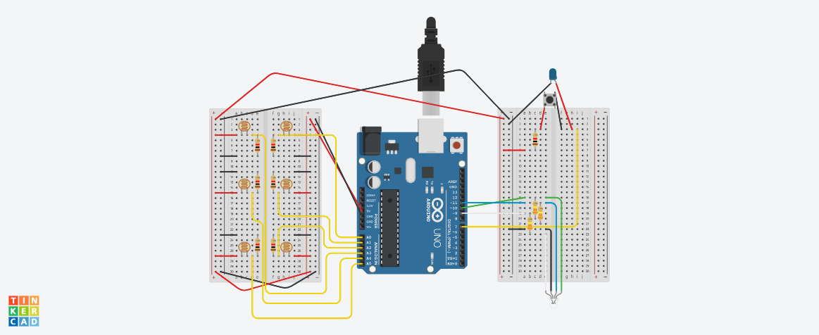
Below is my (highly confusing) assembly diagram of the project, as created using TinkerCAD.
p5 Code
The p5 code was mostly based on my old code from Assignment 2. However, I had to modify it quite a bit to both work with Serial Communication and also restrict the agar growth to specific plates rather than the entire area of the sketch. Like last time, I used randomGaussian() for the growth. I used this instead of Perlin Noise as I rather liked the higher degree of randomness the Gaussian random gave me, as the Perlin Noise did tend towards aggregation rather than spread, as expected.
Also, to avoid colonies from appearing beyond the plate borders, I just used an if() statement to only display those colonies that were generated within borders. While I originally wanted to use a while() loop to truly restrict generation to within the plate, I soon discovered that a while() loop interfered with Serial Communication, thus causing the program to crash. Since a minimum of 5 and a maximum of 30 colonies were generated every frame, or 60 times per second, I felt that the few colonies leaving the plate borders that would not be displayed wouldn’t really be missed.
for (let i = 0; i < numColonies; i++) {
  // Gaussian random to ensure aggregation towards center
  colonyX = randomGaussian(cultures[d].x, spread);
  colonyY = randomGaussian(cultures[d].y, spread);
  colonyR = random(2, 15);
  if (
    dist(
      colonyX,
      colonyY,
      plates[cultures[d].loc].x,
      plates[cultures[d].loc].y
    ) <=
    plates[d].diameter / 2 - colonyR - 3
  ) {
    strokeWeight(3);
    if (uv) {
      stroke(cultures[d].border);
      fill(cultures[d].col);
    } else {
      stroke(colonyBorder);
      fill(colonyColor);
    }
    ellipse(colonyX, colonyY, colonyR);
  }
}
Serial Communication
Serial Communication in this project was two-directional.
From the p5 sketch, the RGB values of the fluorescent protein colors were sent to the Arduino, which would use these as inputs for red, blue, and green light. I converted the hexadecimal color value to decimal using parseInt() which I learned to use from this tutorial.
let colRgb = hexToRgb(colonyUVColors[currentProt]);
let sendToArduino = colRgb[0] + "," + colRgb[1] + "," + colRgb[2] + "\n";
writeSerial(sendToArduino);
From the Arduino component, the information about which photoresistor had crossed the threshold and was thus the plate on which the user had “dispensed the bacteria” was communicated to the p5 sketch. As explained earlier, this information would only be sent when the light intensity crossed a certain value above background light intensity.
There were numerous challenges faced. I enumerate some of them below.
1) To detect? Or not to detect?
As anyone who uses photoresistors (or any kind of variable resistance sensors really) must know, photoresistors have wildly inconsistent results. Not just that, since their resistance changes according to light intensity, any changes in background light intensity would also potentially trigger false positives, or could even mask actual detections leading to false negatives. Both are bad.
There are two ways of combatting this. The first is to create an enclosure that minimizes background light intensity. A “dark room” as such. My original plan included this in some aspect, as I had planned to build a mini version of a laminar flow hood as the housing for the project. However, due to my lack of any abilities in fabrication, this was out of the question.
So, the next solution lies in code. Instead of trying to detect light intensity above a certain threshold, using the difference in intensity between background light intensity and the light to be detected would be a better solution. So, I decided to put statements asking the Arduino to measure light intensity at startup through the setup() function. But this presents another problem, as you might have guessed. How would I account for changing light intensity during runtime? This could be done by using the button output (the one the user was pressing to pipette) as a condition for when the actual light intensity was being sensed, and otherwise continually detecting background light intensity while the user did not press the button. This actually worked surprisingly reliably, even in weird lighting conditions.
2) Watch me crank that (solder) boy
Soldering was a pain. It looks easy from the outside but I was clearly doing something wrong because making 8 solder connections took me 2.5 hours. One mistake that I discovered I was doing is that in order to “beautify” the solder, I was trying to melt it a bit so that it flowed around the wire better and looked smoother, but the whole thing would melt off and drop unceremoniously. I quickly learned not to do that.
3) If it can’t be fixed by tape, you’re not using enough
As mentioned in my Resources Used section, much of my project is held together with a ton of Scotch tape. I mean, half of an entire roll of Scotch tape. I initially wanted to join the cardboard segments making up the pipette with hot glue, but I quickly discovered that hot glue guns wouldn’t work too well. Not because of the strength of hot glue (hot glue was strong enough), but because the cardboard itself was too weak to handle shear stress from being pressed on while only being linked using hot glue to one/two joints. Tape allows for more surface area of contact and also holds the pieces together like a rubber band would instead of just creating a joint. Also, a bunch of tape was used to hold the aluminium taut against the pizza box both to prevent crinkles and also to avoid the foil itself from shifting around and covering the potentiometer windows.
4) Serial communication: More drama than Hindi TV serials
Serial Communication. It’s a useful tool to create projects linking digital artwork on p5 to physical processes through an Arduino.
But it requires so much bug-fixing to get right.
Right off the bat, as described earlier, a while() loop to keep regenerating random positions that were only within disc borders, while working perfectly fine in a p5-only situation, would crash as soon as it came to Serial Communication, most likely because the while() loop interfered with the Serial receiving/sending of data. This required me to switch to an if() statement to only display those colonies that generated within the plate borders, using the dist() function to calculate distance between centers of colonies and plates.
Also, I noticed that occasionally, Serial communication would stop entirely between the p5 and Arduino components. This, I found, was because my code initially sent a number associated with each light sensor when the corresponding light sensor detected the LED. What happens if it doesn’t detect the LED? You’re right, the Arduino stops sending data, breaking the Serial Communication. This, I fixed by asking the Arduino to send an arbitrarily picked ‘6’ whenever no sensor detected the LED.
The final challenge in fact couldn’t be solved by me. I noticed both during User Testing and the show itself that if the user switched colors too quickly (as excited users wanting to try out the different colors are wont to do) Serial lagged on the Arduino side and the LED would display a color associated with a different protein. The time taken to recover gradually increased with runtime, eventually reaching a longest period of 1 minute of recovery time. I found that p5 was indeed sending the correct information with virtually no delay, but without the ability to get Serial callouts from the Arduino while Serial Communication was running meant that I could not identify what was causing the lag in the Arduino.
User Testing
Reflections
Overall, I’m rather proud of my project. It allowed me to convey my love for Biology and allowed people, irrespective of their background, to try their hand at a simple experiment, without requiring any prior lab prep work or worry of contamination and other challenges when it comes to growing bacteria. Also, the simulation was a lot faster than actual bacteria growth (taking E. coli for example, at full growth, each second is equivalent to about 6 hours). Seeing the excited faces at the IM showcase as the fluorescence under UV was revealed to them was (as cheesy as it sounds) worth all the time I spent on this project. That I would say is the aspect I am most proud of. But other than that, I am particularly proud of my way of detecting the LED light using a difference in light intensity method than a raw threshold, as it eliminated the biggest possible source of variation.
However, there is definitely room for improvement. Most of what I include below comes from feedback actually given to me during the IM showcase, or from behaviors that I observed.
The project was essentially not very intuitive. While I did have a poster with written instructions, like all other written forms of instruction, it was ignored, thus leaving most users confused about what to do without my assistance. The instructions being unclear also didn’t help.
The interaction could flow better. I could map the change in fluorescent proteins to the keyboard instead of mouse clicks as (a) a lot of MacBook users kept accidentally right-clicking on my Windows laptop due to the differences in what is sensed by each device’s trackpad; and (b) most people stuck to the same color for all six plates as they forgot or did not bother with changing the color.
As some of my Biology major friends pointed out, it would be cool if I had six tubes with six LEDs of different colors representing each of the fluorescent proteins. And then, instead of selecting the protein from the screen, I could potentially ask the user to “pipette” from one of the tubes and into each well, just like in a real Biology lab. However, this would require both an RGB sensor, as well as a way to distinguish between pipetting in and out. One button with two different depths (like in real pipettes) wouldn’t work, and two separate would be too cumbersome to hold and press. But, it would definitely increase the immersion if possible.
Resources Used
Most of the electronics were from the base Sparkfun Arduino Uno Rev3 SMD kit. I had to borrow additional photoresistors and an arcade button from the IM lab consumables for the photoresistors. Additionally, I borrowed solid core wires and solder to extend my connections and electrical tape to insulate them.
For the physical prototype itself, the pipette was made of cardboard from the IM lab held together with a LOT of tape a hole was punched into one side of the pipette for the wires, and at the bottom for the LED. A larger hole was made at the top for the arcade button.
The main working surface was based on a pizza box that was covered in foil and punched with six holes to serve as windows for the photoresistors. All of my circuitry went into the pizza box, which would make it convenient to make any quick fixes. I could just open the box and work on it rather than have to cut anything out of a more permanent casing.
Software side, the cover image was generated using DALLE3, while the images of the fluorescent proteins were obtained from the Protein Data Bank (PDB) maintained by the Research Collaboratory for Structural Bioinformatics (RCSB).
My original idea was to create an interactive world map where users could click on regions to listen to the music typical of that area, introducing them to different cultures. However, I later shifted gears to develop a project where users could hear languages spoken in those regions instead. I found this idea exciting because it provides an opportunity to become familiar with various dialects and accents. At one point, I questioned if I was just creating a translator, something readily available through apps like Google. But then I realized the simplicity of my concept: a straightforward map highlighting regions with less commonly known languages. When users click on these areas, they hear their own words spoken back to them in the local language. I want to acknowledge that my inspiration came from the installations at Lulu Island, Manarat Abu Dhabi.
How does the implementation work?
I used switches connected to the Arduino for input handling. Each switch corresponds to a country. When a user presses a switch, the Arduino records which country was selected. I also integrate a microphone to capture the user’s spoken words. The Arduino was set up to process this input when the user spoke. For the Visual Interface I used p5.js which was handling the graphical part of my project, it provided visual feedback when a country was selected and showed the status of voice input and translation. After capturing the audio input from the Arduino, use p5.js to handle the audio data, possibly sending it to a server for speech recognition and translation. The translated text can then be converted back into audio. An important implementation was the Interaction Between Arduino and p5.js their Communication using serial communication to pass the selected country and the captured audio from the Arduino to the p5.js application. I also had to Implement a speech recognition module to transcribe the spoken words into text. For that, I used translation API to translate the text into the selected language. In the end, ensured the implementation for Speech-to-text – TRANSLATION – text-to-Speech was working properly and in the right order.
Description of interaction design
Initially, the design was supposed to be a layered map of the world [the laser cut design] but with the restraint of only being able to use it and the fact that I can only use 6 digital Arduino pins, I have to come up with 6 countries and then mapped out on the world, also than placed them in their respective location, so each. Because of not being able to utilize the laser machines, I had a plan to DYI my map, for I used the available contrasting color papers and then laminated them to get the surface but strong and then Layered them on top of each other {with the wholes so that wiring of the switches was easier).
Description of Arduino code + code snippets
This Arduino script is designed to handle inputs from six different switches, each corresponding to a unique country, and controls an LED and serial communication for each switch. When a switch is pressed, the associated LED turns on and a specific number is sent via serial to a connected p5.js application, indicating the country selected. Each button press triggers a brief activation of the LED and a serial print, followed by a deactivation of the LED after a short delay, ensuring clear feedback for each interaction. The code also debounces the switches to prevent multiple activations from a single press.
#include <Arduino.h>

const int switchPin1 = 2; //turkish
const int switchPin2 = 3; //korean
const int switchPin3 = 4; //arabic
const int switchPin4 = 5; //spanish
const int switchPin5 = 6; //Russian
const int switchPin6 = 7; //Japanease

const int ledPin1 = 8; //turkish
const int ledPin2 = 9; //korean
const int ledPin3 = 10; //arabic
const int ledPin4 = 11; //spanish
const int ledPin5 = 12; //Russian
const int ledPin6 = 13; //Japanease

// Variables to store the last state of each button
bool lastState1 = HIGH; //turkish
bool lastState2 = HIGH; //korean
bool lastState3 = HIGH; //arabic
bool lastState4 = HIGH;
bool lastState5 = HIGH;
bool lastState6 = HIGH;

void setup() {
  pinMode(ledPin1, OUTPUT); //turkish
  pinMode(ledPin2, OUTPUT); //korean
  pinMode(ledPin3, OUTPUT); //arabic
  pinMode(ledPin4, OUTPUT);
  pinMode(ledPin5, OUTPUT);
  pinMode(ledPin6, OUTPUT);

  pinMode(switchPin1, INPUT_PULLUP); //turkish
  pinMode(switchPin2, INPUT_PULLUP); //korean
  pinMode(switchPin3, INPUT_PULLUP); //arabic
  pinMode(switchPin4, INPUT_PULLUP);
  pinMode(switchPin5, INPUT_PULLUP);
  pinMode(switchPin6, INPUT_PULLUP);

  Serial.begin(9600);
}

void loop() {
  bool currentState1 = digitalRead(switchPin1); //turkish
  bool currentState2 = digitalRead(switchPin2); //korean
  bool currentState3 = digitalRead(switchPin3); //arabic
  bool currentState4 = digitalRead(switchPin4);
  bool currentState5 = digitalRead(switchPin5);
  bool currentState6 = digitalRead(switchPin6);

  // Check if button 2 was pressed (state change from HIGH to LOW)
  if (lastState1 == HIGH && currentState1 == LOW) { //turkish
    digitalWrite(ledPin1, HIGH); // Turn on LED
    Serial.println("1"); // Send "2" to p5.js
    delay(3000); // Short debounce delay
    digitalWrite(ledPin1, LOW); // Turn off LED
  }

  // Check if button 2 was pressed (state change from HIGH to LOW)
  if (lastState2 == HIGH && currentState2 == LOW) { //korean
    digitalWrite(ledPin2, HIGH); // Turn on LED
    Serial.println("2"); // Send "2" to p5.js
    delay(3000); // Short debounce delay
    digitalWrite(ledPin2, LOW); // Turn off LED
  }

  // Check if button 3 was pressed (state change from HIGH to LOW)
  if (lastState3 == HIGH && currentState3 == LOW) { //arabic
    digitalWrite(ledPin3, HIGH); // Turn on LED
    Serial.println("3"); // Send "3" to p5.js
    delay(3000); // Short debounce delay
    digitalWrite(ledPin3, LOW); // Turn off LED
  }

  // Check if button 4 was pressed (state change from HIGH to LOW)
  if (lastState4 == HIGH && currentState4 == LOW) {
    digitalWrite(ledPin4, HIGH); // Turn on LED
    Serial.println("4"); // Send "4" to p5.js
    delay(10); // Short debounce delay
    digitalWrite(ledPin4, LOW); // Turn off LED
  }

  // Check if button 5 was pressed (state change from HIGH to LOW)
  if (lastState5 == HIGH && currentState5 == LOW) {
    digitalWrite(ledPin5, HIGH); // Turn on LED
    Serial.println("5"); // Send "5" to p5.js
    delay(3000); // Short debounce delay
    digitalWrite(ledPin5, LOW); // Turn off LED
  }

  // Check if button 6 was pressed (state change from HIGH to LOW)
  if (lastState6 == HIGH && currentState6 == LOW) {
    digitalWrite(ledPin6, HIGH); // Turn on LED
    Serial.println("6"); // Send "6" to p5.js
    delay(3000); // Short debounce delay
    digitalWrite(ledPin6, LOW); // Turn off LED
  }

  // Update last states
  lastState1 = currentState1;
  lastState2 = currentState2;
  lastState3 = currentState3;
  lastState4 = currentState4;
  lastState5 = currentState5;
  lastState6 = currentState6;

  delay(100); // Optional: Additional delay to reduce loop cycling speed
}
Description of p5.js code + code snippets + embedded sketch
This p5.js code manages a web-based interface that integrates with Arduino for a language translation project. It handles speech recognition and synthesis, and dynamically changes UI states to guide the user through different stages: from initial welcome, through instructions, to active speech input. The script uses serial communication to receive language selection from Arduino, updates the UI based on this input, and switches between different background images to reflect the current state. Users can initiate speech-to-text translation, which is then translated into the selected language and spoken back, providing an interactive system.
// Global variables for speech recognition and synthesis
let speechRec, speech, output, fromText, toText, langFrom, langTo, latestData;
let serial; // Serial communication object
let screenState = "welcome";
let languages = {};
let bg_img1, bg_img2, bg_img3, bg_img;
let prevData="0";

function preload(){
  bg_img1 = loadImage('assets/Screen1.png');
  bg_img2 = loadImage('assets/Screen2.png');
  bg_img3 = loadImage('assets/Screen3.png');
  bg_img4 = loadImage('assets/Screen1.png');
}
function setup() {
  // bg_img1.loadPixels();
  // bg_img2.loadPixels();
  // bg_img3.loadPixels();
  // bg_img4.loadPixels();
  // noCanvas();
  createCanvas(windowWidth, windowHeight);

  // DOM elements
  output = select("#speech");
  fromText = select("#from-text");
  toText = select("#to-text");
  langFrom = select("#lang-from");
  langTo = select("#lang-to");

  // Populate language dropdowns
  // populateLanguageOptions();

  // Initialize serial communication
  serial = new p5.SerialPort();

  // Event handlers for serial communication
  serial.on("connected", serverConnected);
  serial.on("open", portOpen);
  // serial.on("data", serialEvent);
  // serial.on("error", serialError);
  // serial.on("close", portClose);

  // select("#connect").mousePressed(connectSerial);

  // Open the serial port to your Arduino
  serial.open("/dev/cu.usbmodem1201"); // Adjust to match your Arduino's serial port
}

async function connectSerial() {
  // Prompt user to select any serial port.
  port = await navigator.serial.requestPort();
  // Wait for the serial port to open.
  await port.open({ baudRate: 9600 });

  let decoder = new TextDecoderStream();
  inputDone = port.readable.pipeTo(decoder.writable);
  inputStream = decoder.readable;

  reader = inputStream.getReader();
  readLoop();
  loop(); // Start the draw loop again
}

async function readLoop() {
  while (true) {
    const { value, done } = await reader.read();
    if (value) {
      console.log(`Received: ${value}`);
      latestData = value.trim();
    }
    if (done) {
      console.log("Closed the reader stream");
      reader.releaseLock();
      break;
    }
  }
}

function draw() {
  // Use the draw function to react to changes in data received from Arduino

  if (screenState === "welcome") {
    // background(220, 0, 0);
    image(bg_img1,0,0,windowWidth, windowHeight);

  }
  else if (screenState === "instruction") {
    // background(0, 0, 255);
    image(bg_img2,0,0,windowWidth, windowHeight);
  }
  else if (screenState === "speak") {
    // background(0, 255, 0);
    image(bg_img3,0,0,windowWidth, windowHeight);
    serialLanguageChange();
    text("Please Speak Whats on Your Mind", windowWidth/4, (windowHeight/4 - 50))
    text(fromText.value(), windowWidth/4, windowHeight/4)
    text(languages[langTo.value()], windowWidth/4, (windowHeight/4 + 50))
    text(toText.value(), windowWidth/4, (windowHeight/4 + 100))
  }
  else {
    // background(100);
    console.log('last_screen');
    image(bg_img4,0,0,windowWidth, windowHeight);
  }


}

// Populate language selection dropdowns
function populateLanguageOptions() {
  languages = {
    "en-GB": "English",
    "tr-TR": "Turkish",
    "ko-KR": "You were in Korea",
    "ar-SA": "Arabic",
    "ru-RU": "Russian",
    "ja-JP": "Japanese",
    "es-ES": "Spanish",
  };

  for (const [code, name] of Object.entries(languages)) {
    langFrom.option(name, code);
    langTo.option(name, code);
  }

  langFrom.selected("en-GB"); // Default language from
  langTo.selected("en-GB"); // Default language to
}

// Callback for received speech
function gotSpeech() {
  if (speechRec.resultValue) {
    let said = speechRec.resultString;
    // output.html("okay");
    fromText.value(said);
  }
}

// Serial data event handling
function serialEvent() {
  // console.log("In Serial Event");
  // let data = serial.readStringUntil("\r\n").trim(); // Read incoming data
  // console.log("Received from Arduino:", data); // Debugging log
  // if (latestData == "1" && prevData!="1") {
  //   console.log(data, "in");
  //   changeLanguage("tr-TR"); // Change to Korean
  //   prevData=1;
  // } else if (latestData == "2" && prevData!="2") {
  //   changeLanguage("ko-KR"); // Change to Turkish
  //   prevData=2;
  // } else if (latestData === "3" && prevData!="3") {
  //   changeLanguage("ar-SA"); // Change to Turkish
  //   prevData=3;
  // } else if (latestData === "4" && prevData!="4") {
  //   changeLanguage("ru-RU"); // Change to Turkish
  //   prevData=4;
  // } else if (latestData === "5" && prevData!="5") {
  //   changeLanguage("ja-JP"); // Change to Turkish
  //   prevData=5;
  // } else if (latestData === "6" && prevData!="6") {
  //   changeLanguage("uk-UA"); // Change to Turkish
  //   prevData=6;
  // }
}

// Change the translation language and translate text
function changeLanguage(langCode) {
  console.log("Changing language to:", langCode); // Debugging log
  console.log(prevData);
  langTo.selected(langCode); // Set translation language
  if (fromText.value().trim() !== "") {
    translateText(); // Translate the text if non-empty
  }
}

// Translate text using an external API
function translateText() {
  let text = fromText.value().trim();
  let translateFrom = langFrom.value();
  let translateTo = langTo.value();

  console.log("Translating from", translateFrom, "to", translateTo); // Debugging log

  let apiUrl = `https://api.mymemory.translated.net/get?q=${encodeURIComponent(
    text
  )}&langpair=${encodeURIComponent(translateFrom)}|${encodeURIComponent(
    translateTo
  )}`;

  fetch(apiUrl)
    .then((response) => response.json())
    .then((data) => {
      let translatedText = data.responseData.translatedText;
      toText.value(translatedText);
      console.log("Translation complete:", translatedText); // Debugging log
      speakText(translatedText, translateTo);
    })
    .catch((err) => console.error("Translation error:", err));
}

// Speak out the translated text
function speakText(text, lang) {
  speech.setLang(lang); // Set the speech language
  speech.speak(text); // Speak the text
}
// Serial event handlers
function serverConnected() {
  console.log("Connected to Serial Server");
}

function portOpen() {
  console.log("The serial port is open.");
}

function serialError(err) {
  console.log("Serial Error:", err);
}

function portClose() {
  console.log("The serial port is closed.");
}

function keyTyped() {
  if (screenState === "welcome") {
    if (key == "c") {
    connectSerial()
    }

    if (keyCode == ENTER) {
      screenState = "instruction";

    }
  }
  else if (screenState === "instruction") {
    if (keyCode == ENTER) {
      htmlElements();
      populateLanguageOptions();
      // Initialize speech recognition and synthesis
      speechRec = new p5.SpeechRec("en-US", gotSpeech);
      speech = new p5.Speech();
      speechRec.continuous = true;
      speechRec.interimResults = false;
      speechRec.start();
      serial.on("data", serialEvent);
      serial.on("error", serialError);
      serial.on("close", portClose);
      screenState = "speak";
    }
  }
  else if (screenState === "speak") {
    if (key === "r") {
      removeHtmlElements();
      resetAll();
      screenState = "welcome";
    }
  }
}

function htmlElements() {
  fromText = createInput('');
  fromText.position(-1000, -30);
  fromText.size(160);
  fromText.attribute('placeholder', 'Text to translate');
  fromText.id('from-text');  // Assign ID for consistency

  toText = createInput('');
  toText.position(-1000, -60);
  toText.size(160);
  toText.attribute('placeholder', 'Translated text will appear here');
  toText.attribute('disabled', true);
  toText.id('to-text');  // Assign ID for consistency

  langFrom = createSelect();
  langFrom.position(-1000, -90);
  langFrom.id('lang-from');  // Assign ID for consistency

  langTo = createSelect();
  langTo.position(-1000, -120);
  langTo.id('lang-to');
}


function removeHtmlElements() {
  if (fromText) {
    fromText.remove();
    fromText = null; // Clear the variable to prevent errors
  }
  if (toText) {
    toText.remove();
    toText = null; // Clear the variable to prevent errors
  }
  if (langFrom) {
    langFrom.remove();
    langFrom = null; // Clear the variable to prevent errors
  }
  if (langTo) {
    langTo.remove();
    langTo = null; // Clear the variable to prevent errors
  }
}

function serialLanguageChange(){
  if (latestData === "1" && prevData!="1") {
    changeLanguage("tr-TR"); // Change to Turkish
    prevData="1"
  } else if (latestData === "2" && prevData!="2") {
    changeLanguage("ko-KR"); // Change to Korean
    prevData="2"
  } else if (latestData === "3" && prevData!="3") {
    changeLanguage("ar-SA"); // Change to Arabic
    prevData="3"
  } else if (latestData === "4" && prevData!="4") {
    changeLanguage("ru-RU"); // Change to Thai
    prevData="4"
  } else if (latestData === "5" && prevData!="5") {
    changeLanguage("ja-JP"); // Change to German
    prevData="5"
  } else if (latestData === "6" && prevData!="6") {
    changeLanguage("es-ES"); // Change to Kazakh
    prevData="6"
   }
}


function resetAll() {
  // Remove HTML elements
  // removeHtmlElements();

  // Reset the speech recognizer and synthesizer
  // if (speechRec) {
  //   speechRec.stop(); // Stop the speech recognizer
  // }
  if (speech) {
    speech.cancel(); // Stop any ongoing speech synthesis
  }

  // Optionally reset any other state, e.g., clearing input fields or logs
  // if (output) {
  //   output.html(""); // Clear any displayed output
  // }

  // Reset the serial communication or any other interfaces
  if (serial) {
    serial.clear(); // Clear the data from the serial port
    serial.close(); // Close the serial port
  }

  // Reset global variables if necessary
  latestData = null;

  // if (speechRec) {
  //   speechRec.stop(); // Stop the speech recognizer if it's running
  // }

  // Reinitialize components if needed immediately
  // setupSpeech();
  // setupHtmlElements();  // Assume you have a function to setup HTML elements again if needed immediately
  // populateLanguageOptions();
}
Challenges faced and how you tried to overcome them
There were 3 main phases in which I faced the challenges: Ideation (what should it be, a music system telling about the different regions or language translator) – Figuring out the Arduino ( I was planning that each time when the user presses on the country using the button there would be a LED with it too which will glow) – and finally integrating the API and ensuring its serial communication with Arduino, also the API was giving me the translation but then connecting that with the P5js speech library was another task that I had a really hard time figuring out. Also when I was making the text-to-speech activated after the translation, I had to make sure that the translated text was spoken in the particular region’s Language. Because It was giving me the error of speaking the translated text in an English accent, it was just like a foreigner trying to speak your native language, so I had to fix and I think this took the most time for my error to resolve time. Apart from that When I was integrating the images for different screens, when I added the last screen it gave me a hard time again, but yeah it was just about playing around with the code that then helped me fix the error.
What are some areas for future improvement?
The API I was using did not help me in translating lots of languages, only the main languages that were translated were the common ones, and also if I could get a good physical interface that would fit my Arduino init hiding all of the wiring and connections. Also, I can integrate more pins in the digital pins section to add more countries?
For my final project, I made an interactive mood lamp with five push-buttons corresponding to five moods: Day, Calm, Study, Energetic, and Night. Each mood lights up with a matching color on the arduino and p5, as well as background music from p5.
Implementation
I used a total of 5 push-buttons (obtained from the IM Lab), each for one of the moods. I also used a potentiometer to control the light brightness, an RGB LED for the light itself, and some 220ohm resistors I had at home (because I lost the ones from the kit), as well as the breadboard and jumper wires.
Each button is connected to one of the arduino’s digital ports; I used the internal pullup resistors for them to reduce the amount of components needed and to make the circuit simpler. The RGB LED is connected through resistors to PWM ports to have control over the brightness. The potentiometer is connected to an analog input.
When the arduino starts, the light is set to orange as a starting color, with a matching screen on p5 prompting the user to select a mood. Whenever any of the five buttons are pressed, the light switches to that mood’s color, as well as the p5 screen, and matching music is played. Light brightness can be controlled continuously through the potentiometer.
Arduino Code
// Pin definitions for buttons
const int greenButtonPin = 2;
const int redButtonPin = 4;
const int blueButtonPin = 7;
const int whiteButtonPin = 5;
const int blackButtonPin = 6;

// Pin definitions for RGB LED
const int redLEDPin = 9;
const int greenLEDPin = 10;
const int blueLEDPin = 11;

// Pin definition for the potentiometer
const int potPin = A0;

// Variable to store the last pressed button
int lastPressedButton = 0;

// Current color variables (Default set to orange)
int currentRed = 255;
int currentGreen = 50;
int currentBlue = 0;

void setup() {
  Serial.begin(9600);

  // Initialize button pins
  pinMode(greenButtonPin, INPUT_PULLUP);
  pinMode(redButtonPin, INPUT_PULLUP);
  pinMode(blueButtonPin, INPUT_PULLUP);
  pinMode(whiteButtonPin, INPUT_PULLUP);
  pinMode(blackButtonPin, INPUT_PULLUP);

  // Initialize RGB LED pins
  pinMode(redLEDPin, OUTPUT);
  pinMode(greenLEDPin, OUTPUT);
  pinMode(blueLEDPin, OUTPUT);

  // Set initial LED color and brightness to maximum
  updateBrightness(255); // Ensure full brightness on startup
  setColor(currentRed, currentGreen, currentBlue); // Start with default mood 'Start' (Orange)
  Serial.println("Start");
}

void loop() {
  // Continuously adjust the brightness based on potentiometer reading
  int brightness = analogRead(potPin) / 4; // Scale to 0-255
  updateBrightness(brightness);

  // Check each button and change the LED color and print the mood if changed
  checkButton(greenButtonPin, "Study", 0, 255, 0);
  checkButton(redButtonPin, "Energetic", 255, 0, 0);
  checkButton(blueButtonPin, "Calm", 0, 0, 255);
  checkButton(whiteButtonPin, "Day", 255, 255, 255);
  checkButton(blackButtonPin, "Night", 128, 0, 128);
}

void setColor(int red, int green, int blue) {
  // Store the current color settings
  currentRed = red;
  currentGreen = green;
  currentBlue = blue;
}

void updateBrightness(int brightness) {
  // Adjust the PWM output to LED pins based on the current color and new brightness
  analogWrite(redLEDPin, map(currentRed, 0, 255, 0, brightness));
  analogWrite(greenLEDPin, map(currentGreen, 0, 255, 0, brightness));
  analogWrite(blueLEDPin, map(currentBlue, 0, 255, 0, brightness));
}

void checkButton(int buttonPin, String mood, int red, int green, int blue) {
  if (digitalRead(buttonPin) == LOW && lastPressedButton != buttonPin) {
    delay(50); // Debounce delay
    if (digitalRead(buttonPin) == LOW) { // Confirm the button is still pressed
      lastPressedButton = buttonPin;
      setColor(red, green, blue);
      updateBrightness(analogRead(potPin) / 4); // Update brightness immediately with new color
      Serial.println(mood);
    }
  }
}
Basically, whenever a button corresponding to a mood other than the current one is clicked, the LED color is updated to the color corresponding to the new mood and the mood name is sent to P5 over serial communication. Additionally, the LED brightness is being continuously updated based on changes to the reading from the potentiometer.
P5 Code
let bgColor = [255, 165, 0]; // Orange Starting Color
let moodText = "Mood Lamp"; // Default text to display
let mood = "Start"

// Music Variables
let dayMusic;
let calmMusic;
let studyMusic;
let energeticMusic;
let nightMusic;

// Load all audio
function preload() {
  dayMusic = loadSound('Wii Sports - Title (HQ).mp3');
  calmMusic = loadSound('Animal Crossing New Leaf Music - Main Theme.mp3');
  studyMusic = loadSound('Gusty Garden Galaxy Theme - Super Mario Galaxy.mp3');
  energeticMusic = loadSound('Title Screen - Mario Kart Wii.mp3');
  nightMusic = loadSound('Luma - Super Mario Galaxy.mp3');
}

// Setup canvas
function setup() {
  createCanvas(windowWidth, windowHeight);
  textSize(32);
  textAlign(CENTER, CENTER);
}

function draw() {
  background(bgColor);
  fill(255);
  text(moodText, width / 2, height / 2);

  if (!serialActive) {
    text("Click the screen to select Serial Port", width / 2, height / 2+50)
  }
  else if (mood == "Start") {
    bgColor = [255, 165, 0];
    moodText = "Select one of the mood buttons to being...";
    dayMusic.stop();
    calmMusic.stop();
    studyMusic.stop();
    energeticMusic.stop();
    nightMusic.stop();
  }

  if (mood == "Day") {
    bgColor = [200, 200, 200];
    moodText = mood;
    calmMusic.stop();
    studyMusic.stop();
    energeticMusic.stop();
    nightMusic.stop();
    if (!dayMusic.isPlaying()) dayMusic.loop();
  }

  if (mood == "Calm") {
    bgColor = [0, 0, 255];
    moodText = mood;
    dayMusic.stop();
    studyMusic.stop();
    energeticMusic.stop();
    nightMusic.stop();
    if (!calmMusic.isPlaying()) calmMusic.loop();
  }

  if (mood == "Study") {
    bgColor = [0, 255, 0];
    moodText = mood;
    calmMusic.stop();
    dayMusic.stop();
    energeticMusic.stop();
    nightMusic.stop();
    if (!studyMusic.isPlaying()) studyMusic.loop();
  }

  if (mood == "Energetic") {
    bgColor = [255, 0, 0];
    moodText = mood;
    calmMusic.stop();
    dayMusic.stop();
    studyMusic.stop();
    nightMusic.stop();
    if (!energeticMusic.isPlaying()) energeticMusic.loop();
  }

  if (mood == "Night") {
    bgColor = [128, 0, 128];
    moodText = mood;
    calmMusic.stop();
    dayMusic.stop();
    studyMusic.stop();
    energeticMusic.stop();
    if (!nightMusic.isPlaying()) nightMusic.loop();
  }

}

// Serial code copied from example sketch, with some modifications

function mousePressed() {
  if (!serialActive) {
    // important to have in order to start the serial connection!!
    setUpSerial();
  } else mood = "Start";
}

function readSerial(data) {
  if (data != null) {
    // make sure there is actually a message
    // split the message
    mood = trim(data);
  }
}

function windowResized() {
  resizeCanvas(windowWidth, windowHeight);
}
Basically, after serial connection is established by the user, the canvas is updated to reflect the current mood whenever a new mood is read from the arduino on the serial connection, and the corresponding audio plays as well.
P5 Embedded
User Testing
I had each of my sisters my project to try (prior to making a case and finalizing it).
My first sister managed to figure it out without any instructions from me, surprisingly even knew which COM port to select. She did not figure out that brightness can be controlled by the potentiometer though.
My other (younger) sister managed the same, but did not know which what to do when the COM port prompt came up. She also did not realize that brightness can be controlled.
I had built the casing using cardboard I got from Rahaf from Student Affairs. The material is very flimsy and I should replace it with something more permanent and stable. I had to solder wires to the red button immediately before the showcase because it didn’t have any; I also used two blue buttons because I couldn’t find a white one.
Additionally, I could aim to make the project more fun and interactive, but overall it’s a nice idea that people seemed to enjoy at the showcase.
To summarize this project was about making a game that was like Russian Roulette but without the gun. Instead two players would stand opposite each other and would have two options. First there is a “gun” (it just exists in the p5js sketch) that is loaded with a certain amount of live rounds and the rest are blank and then like the real Russian Roulette each player would get chances to shoot the other opponent or not or shoot themselves. If a player shoots themselves and its a blank then they get another turn making it more likely that the next round will be live and hence more likely that they will win and if they do shoot the other player and it is blank then their turn ends and they swap and the cycle continues. There is also 3 lives for each player and if one of them loses, i.e. runs out of lives they have to use a shock pen. The purpose of the shock pen was to create some kind of stakes just like the real Russian Roulette but more sane.
To me this project represents more than a fun creation. Genuinely, while I did enjoy it this was a huge learning experience and not just when it came to coding and soldering and whatever other physical things I did. I’ll explain how so as I go from beginning to end.
I originally had this idea before the midterm and I thought about creating a Russian roulette for my midterm. I chose a different path and made a Mexican Standoff game for my midterm. It was arguably slightly harder to make and for me going into it I really had little idea what I was doing. I learned how to change from different scenes (thanks to Pi telling me about a scene management class), but more importantly I learned a lot about planning as halfway through making it I had to sit down and I sketched a diagram of what I wanted the game to be like on a whiteboard in a library study room.
So in the midterm I just began to plan things properly and I wasn’t very efficient at it. So going into this project I also planned but unlike before I also had to consider the physical: Making and wiring all the components that I’ll need. Even planning it was difficult to be honest. Difficult because I didn’t really know where to start but also I didn’t know what was available in the intro to IM lab. I was very fortunate to learn more about what was available through our lessons where we learned about renting equipment but also saw the different sections in the lab, like the consumables or the blue closet (i dont know if it has a name).
Then when I had to start I had to learn serial communication. I think a lot of people can agree when I say it was very confusing and I would argue it remained a problem with my project from beginning to end even though I thought I understood it at the beginning. That was the biggest hurdle by far mentally because it had been bothering me for a couple days before because when I would go to try to understand the code from professor Aaron and change it to fit my project (4 buttons, a potentiometer and 2 LEDs) it wouldn’t work even though just before that it I felt I understood it when working with Snehil and Khalifa on the previous assignment.
Include some pictures / video of your project interaction
How does the implementation work?
Description of interaction design
Description of Arduino code and include or link to full Arduino sketch
Description of p5.js code and embed p5.js sketch in post
Description of communication between Arduino and p5.js
What are some aspects of the project that you’re particularly proud of?
What are some areas for future improvement?
The way that my project works is first that the Arduino detects the button presses from each of the four buttons as well as the input from the potentiometer. Then using serial communication the Arduino sends the signals received from the buttons and potentiometer to the p5js sketch and in response the sketch relays back a message to create a handshake.
The p5js code is slightly more complex. First I have multiple scenes each of which managed by a scene management class where depending on the number that the class receives it calls on different functions, each of those functions are actually the scenes. For example the disclaimer scene is actually just a function which has all the shapes and so on being drawn and the function itself is only called upon when the scene number is 2. The same goes for the other scenes. As for the game itself: Firstly, after the animation there is an array of booleans totaling 6. If an element is true it means it is a live round and vice versa and then there is another global variable called selected_round and that is added up incrementally to signify which round is being selected from the chamber. As for the players, they have two options represented as two buttons. One button (the red one) means that the player can shoot themselves, and the other (the blue button) means that the player can shoot the other person in front of them. If the player chooses to shoot themselves and it’s a blank then it remains their turn and makes it more likely that the next round will be live and hence more likely that they can win the round. However, if a player chooses to shoot the other but it’s blank they switch turns making the odds in the favor of the other player as its now more likely for them that the next round is live. Furthermore, I added difficulties which means that depending on the difficulty chosen by the player there will be a varying amount of live rounds with the easiest difficulty being “Standard” which means only one live round, and the hardest being “Masochist” which can have between 3 and 5. Each of the players have 3 lives, then at the end of it all, if they choose to the loser has to use a shock pen so that there are stakes and to make the game more interesting.
I’m particularly proud of the UI elements, specifically holding down a button to go to the next page and so on. To me it felt the most satisfying.
For the future there are a lot of things I would change. I would have started by making the game aspect first, as I had made the mistake of starting at the start page ironically. This would have made my life a lot easier but at the same time I am somewhat glad that I did what I did because I felt that the UI was a large part of what I liked and I hope others liked about the game.
The sketch on p5js may be a bit weird because I had coded it on vscode and made it such that the canvas fit my mac screen so it may take a while to load and/or may be hard to use.

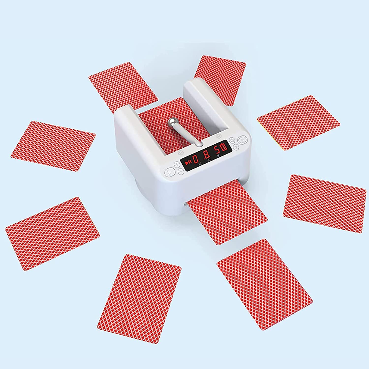
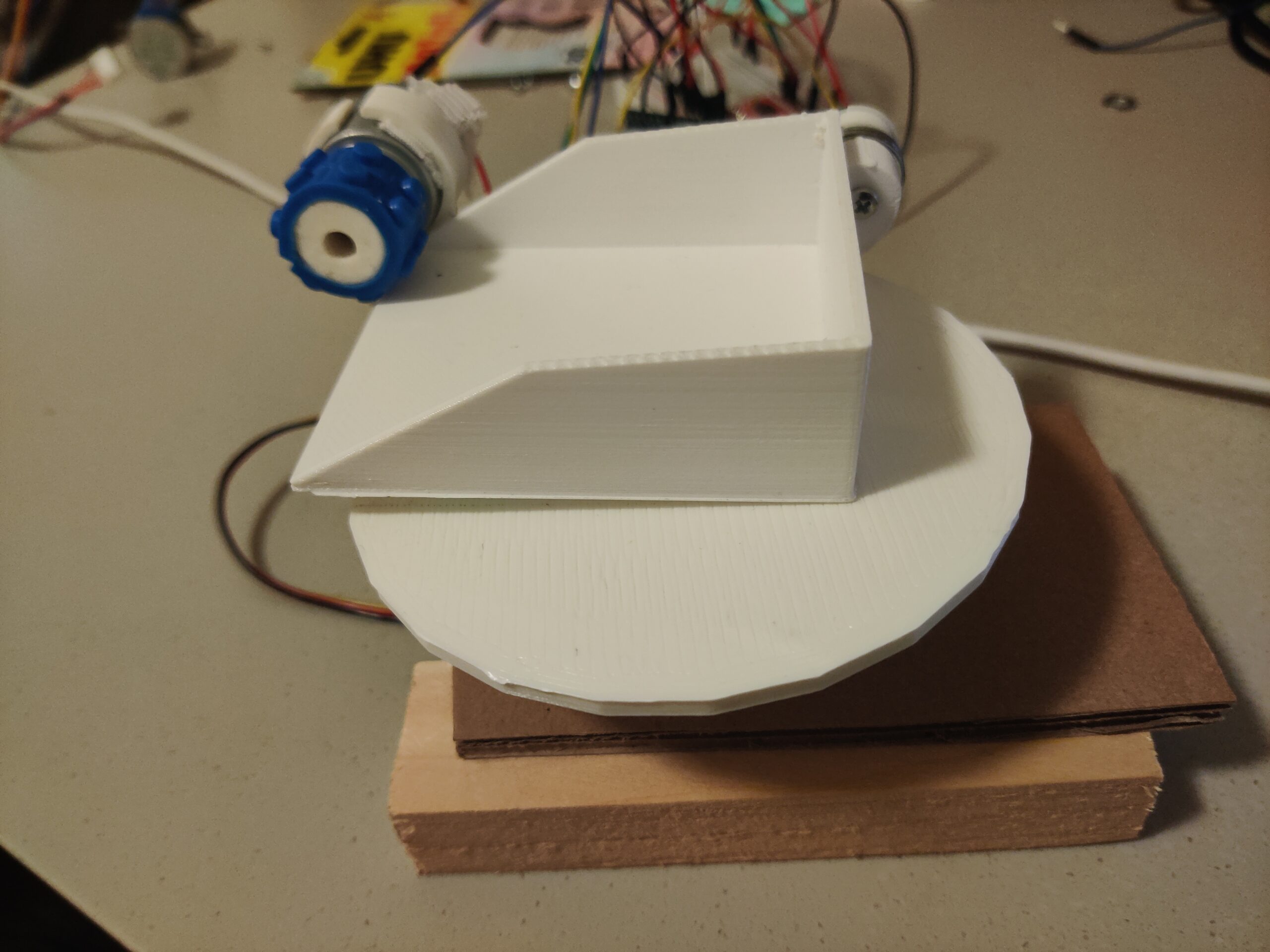
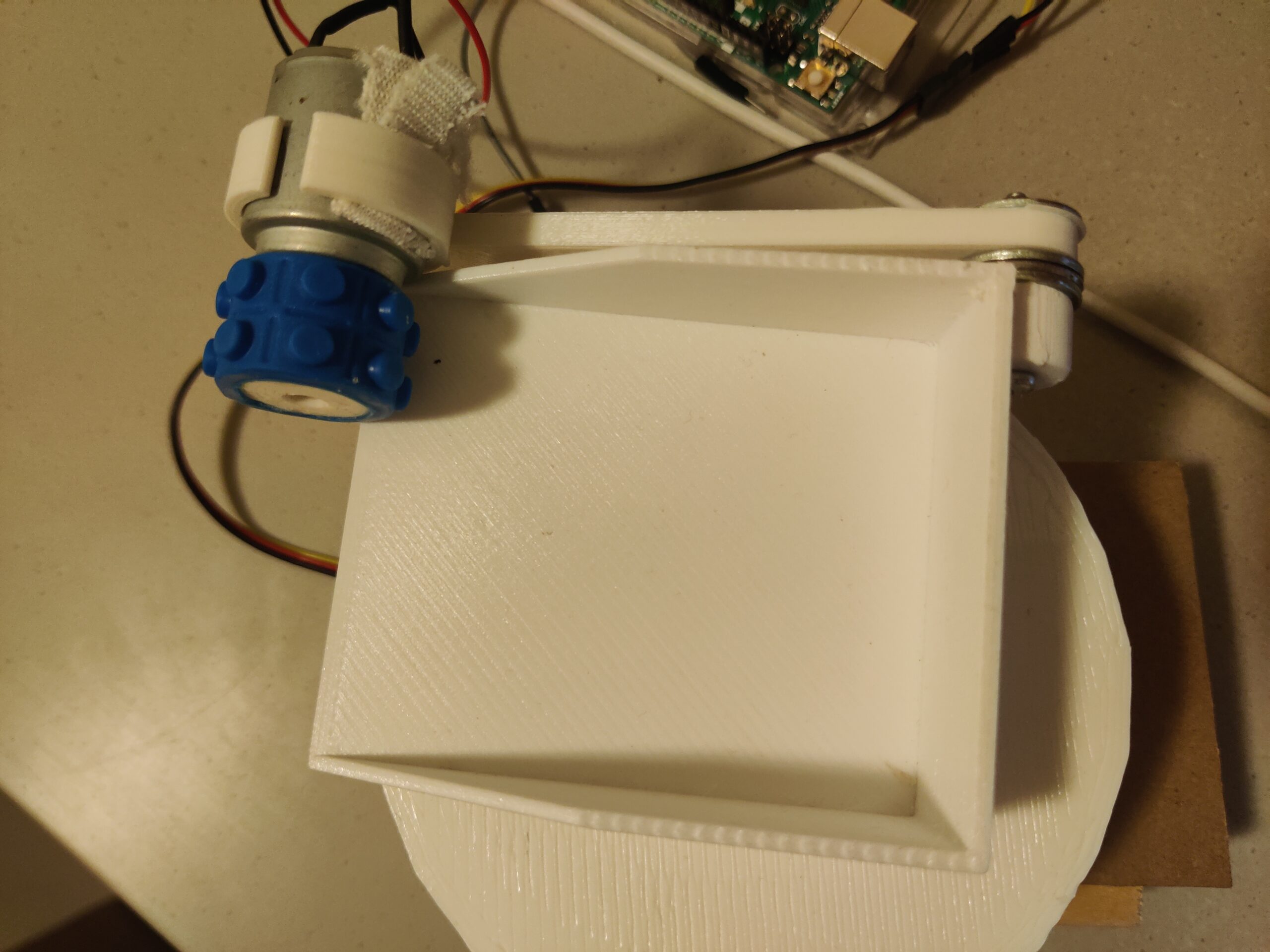
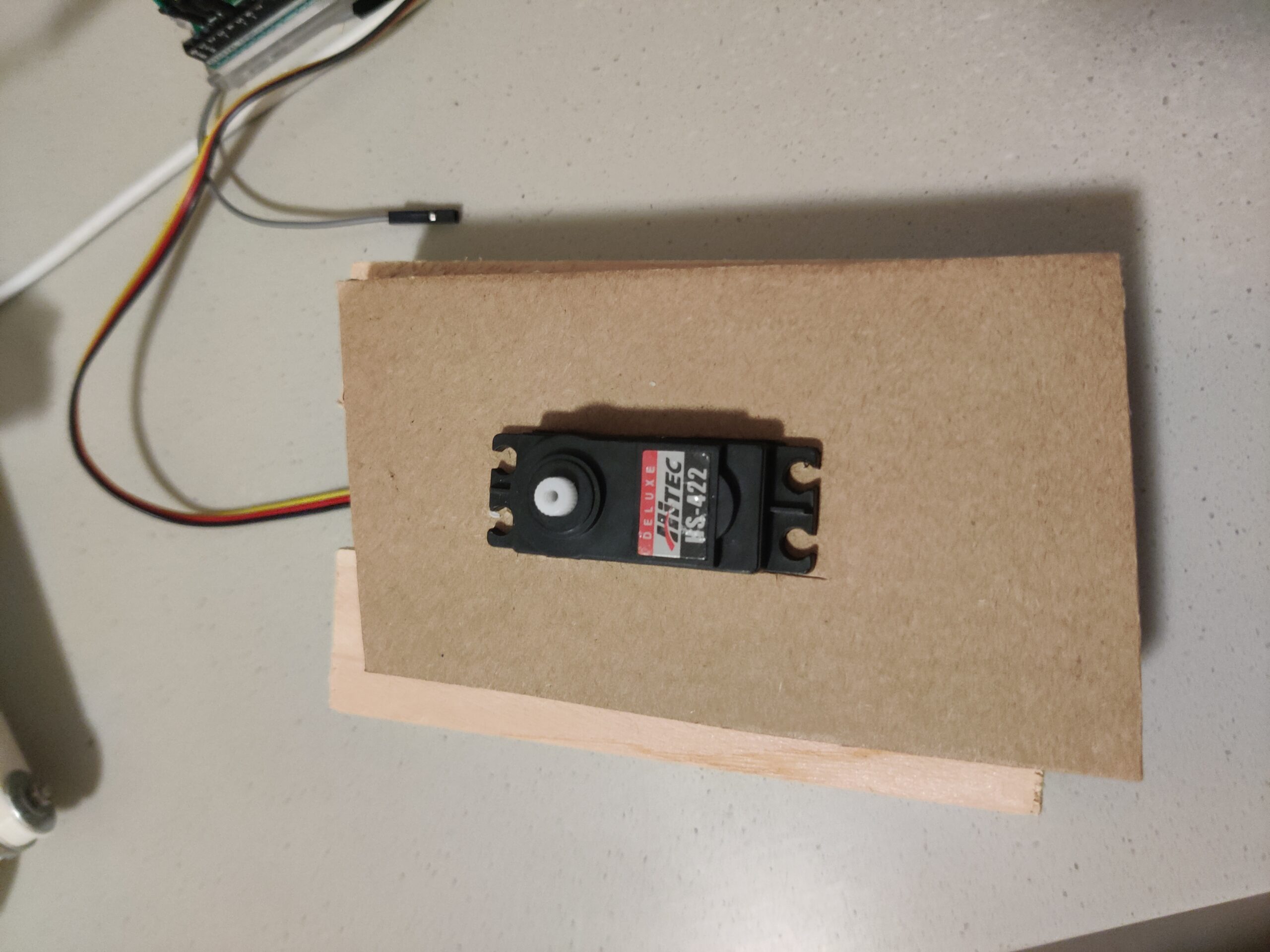
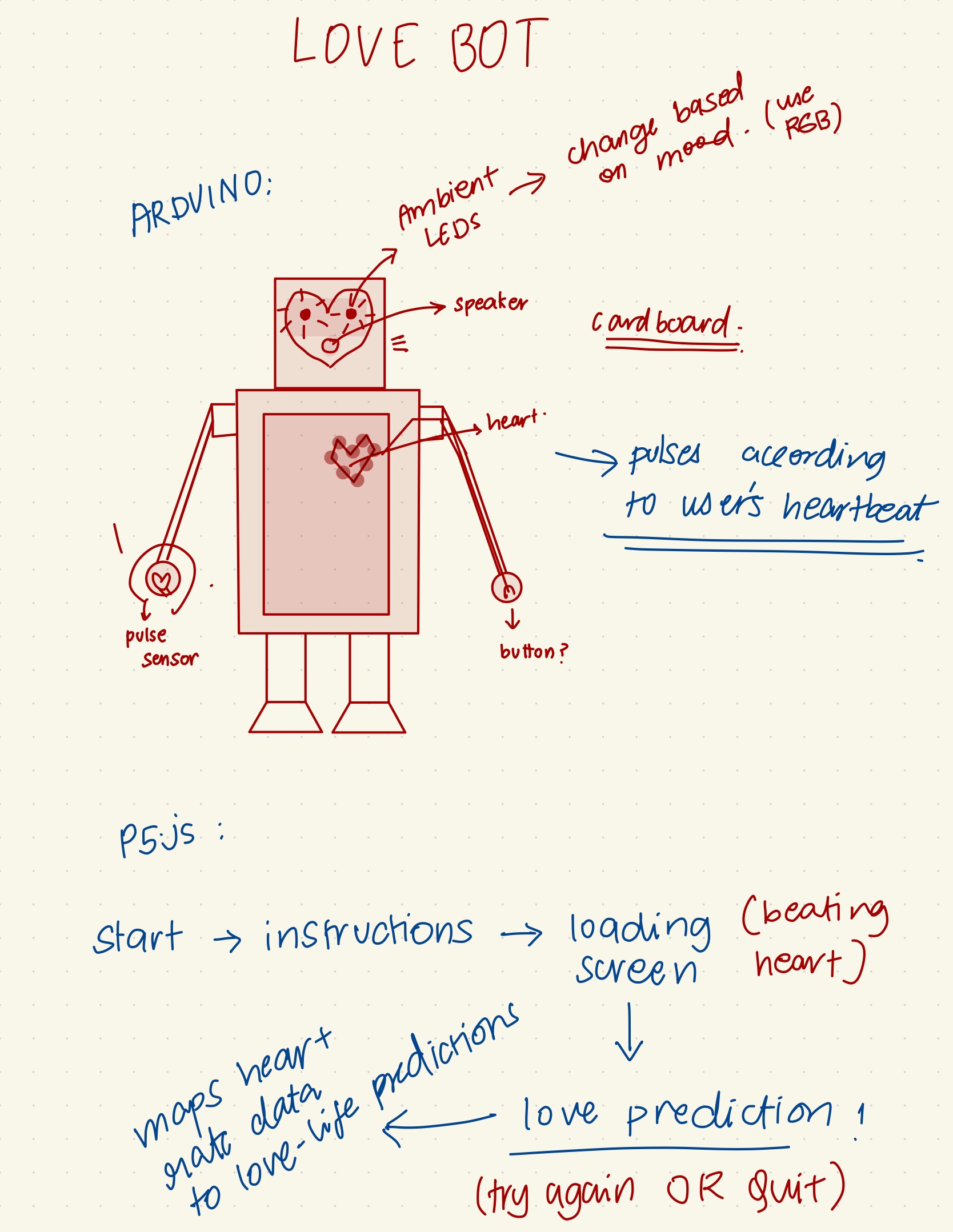
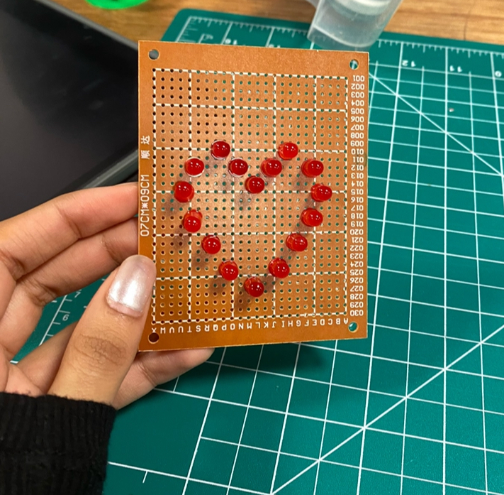
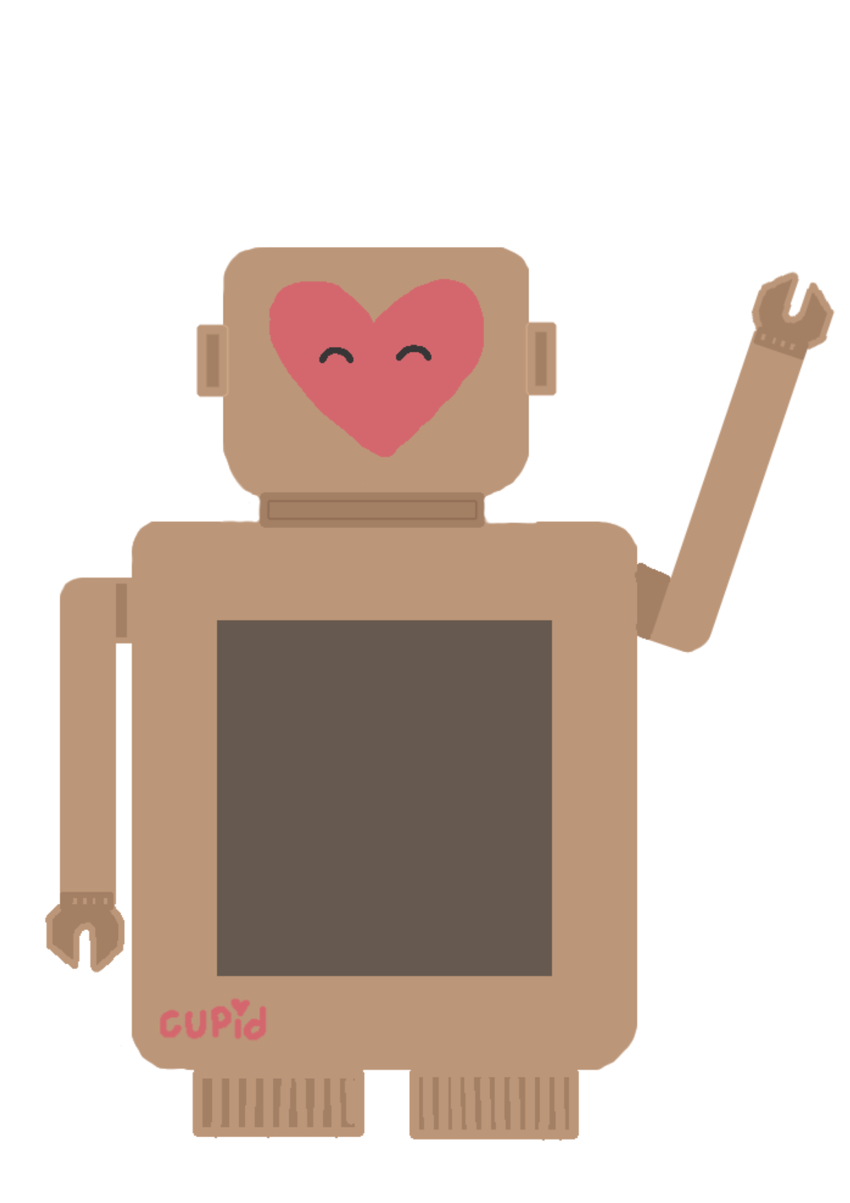

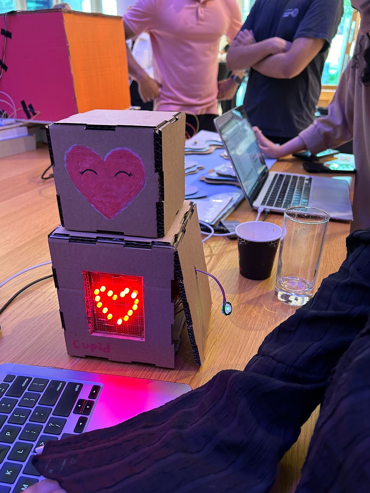
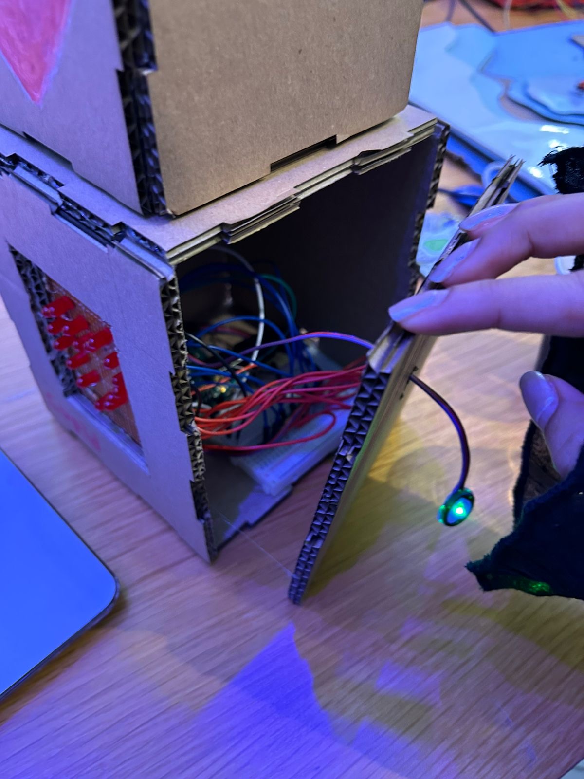
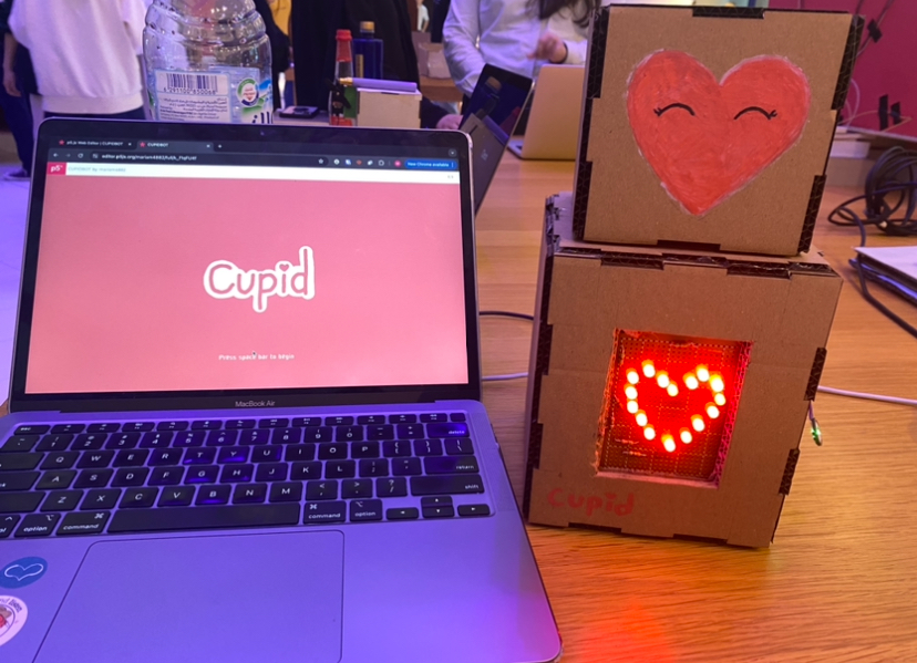
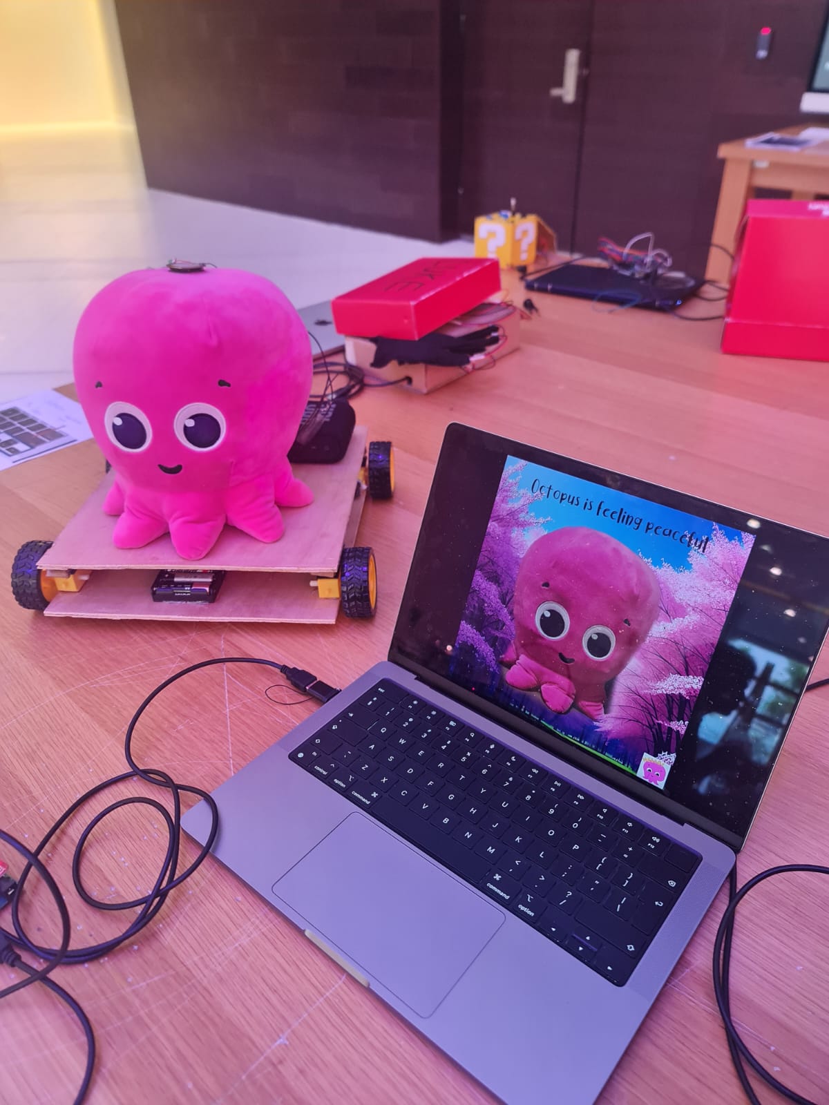 Cover Photo
 Instruction text
 Key Bind visuals
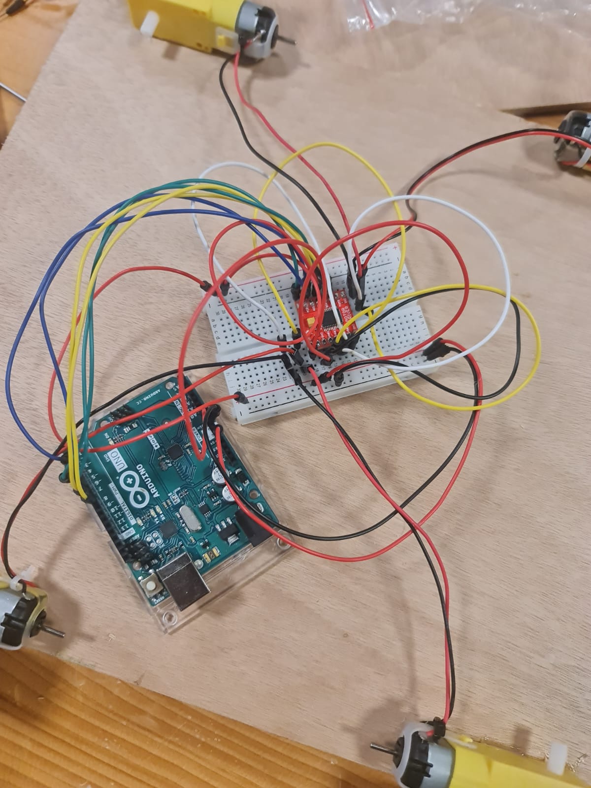 Connections
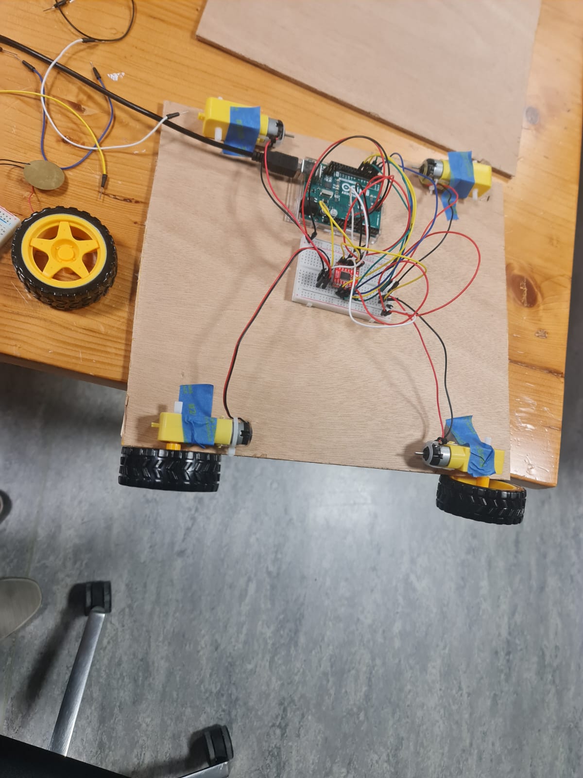 Taped Motors
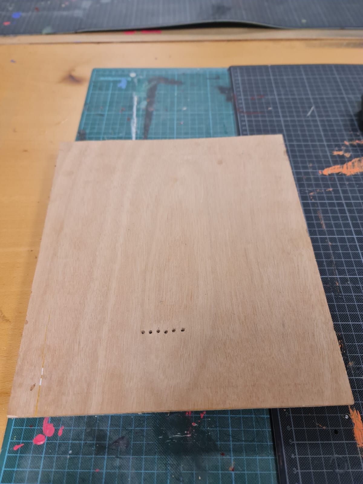 Holes for the wires
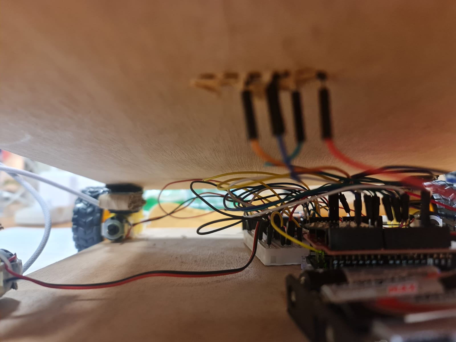 Demonstration of how wires from lower layer were eventually connected
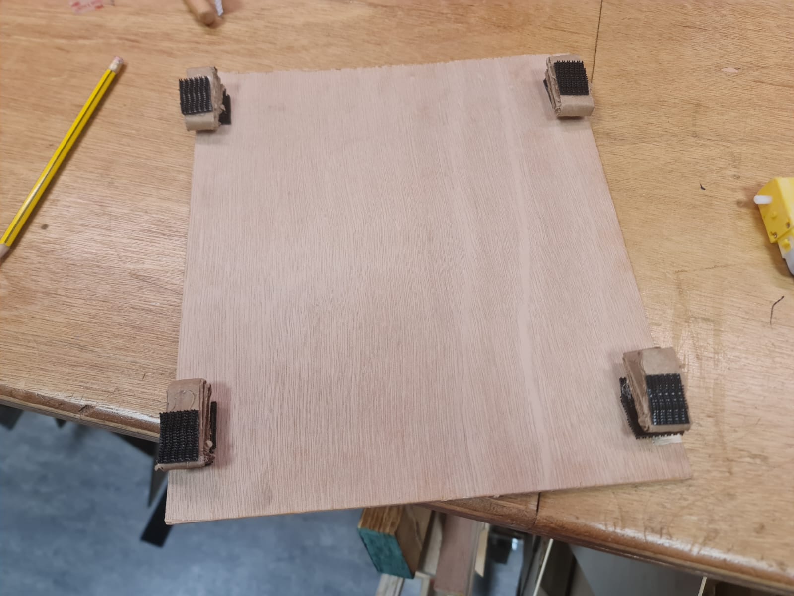 Velcro on top layer
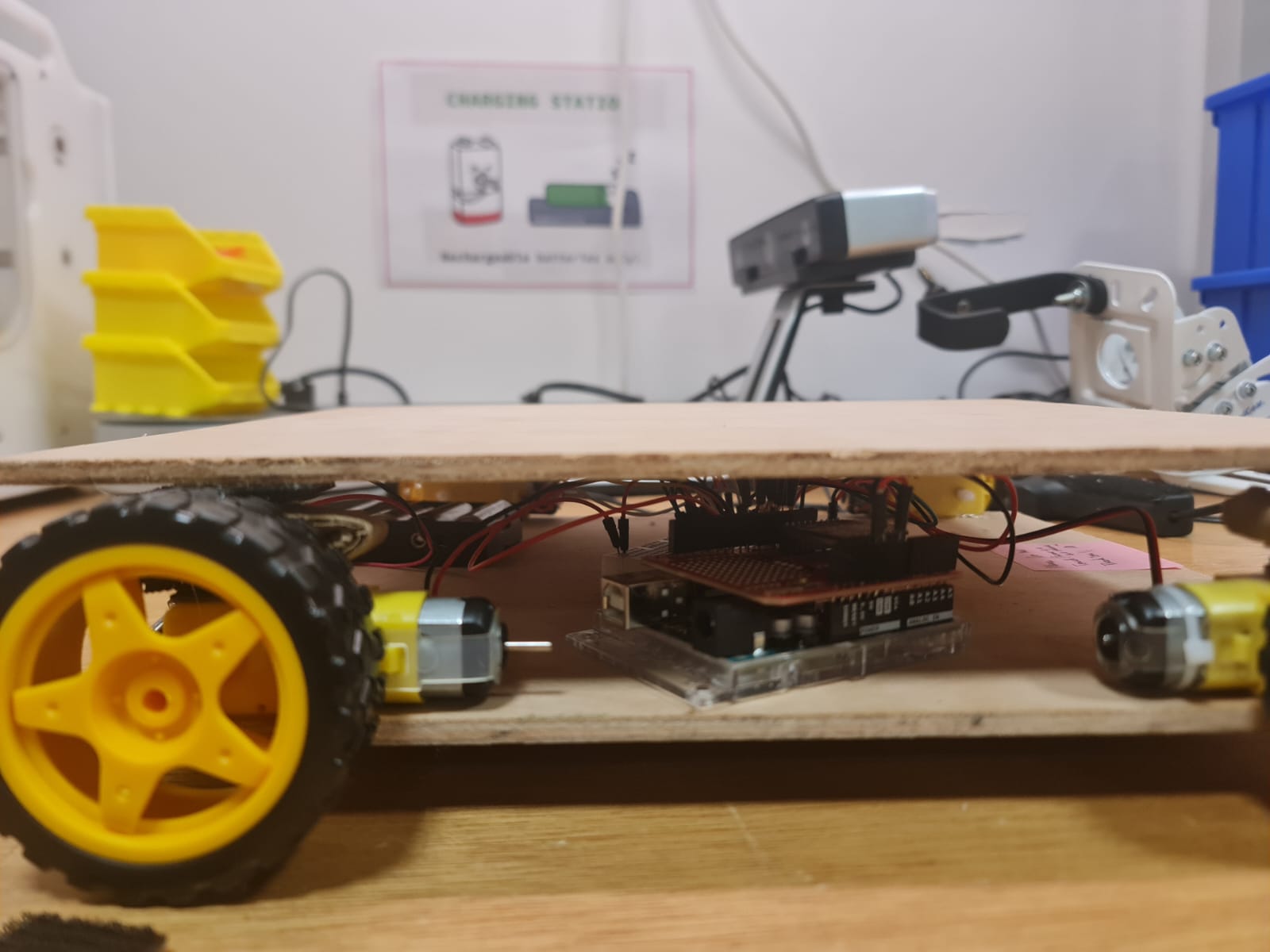 How the layers are joined and the amount of spacing between them
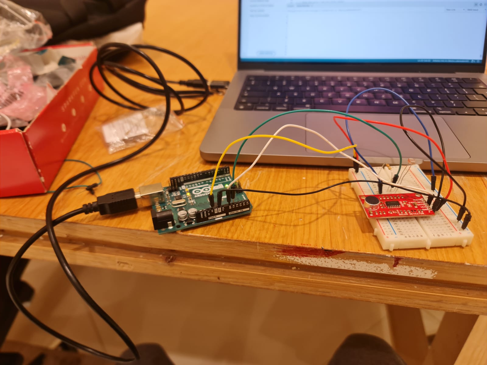 Testing sensors separately
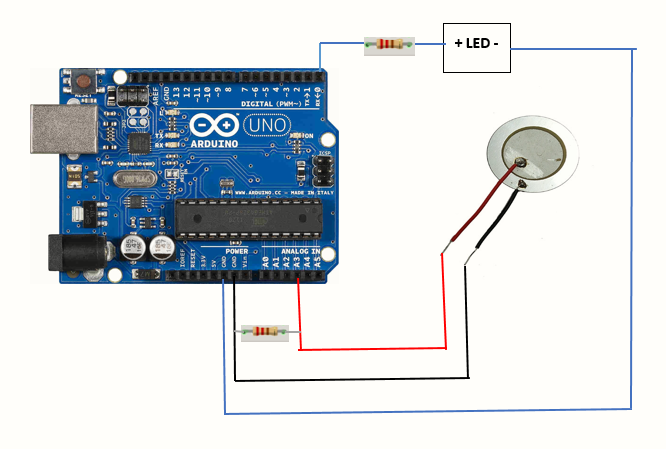 Piezosensor Circuit Diagram
 Motors that came with the kit
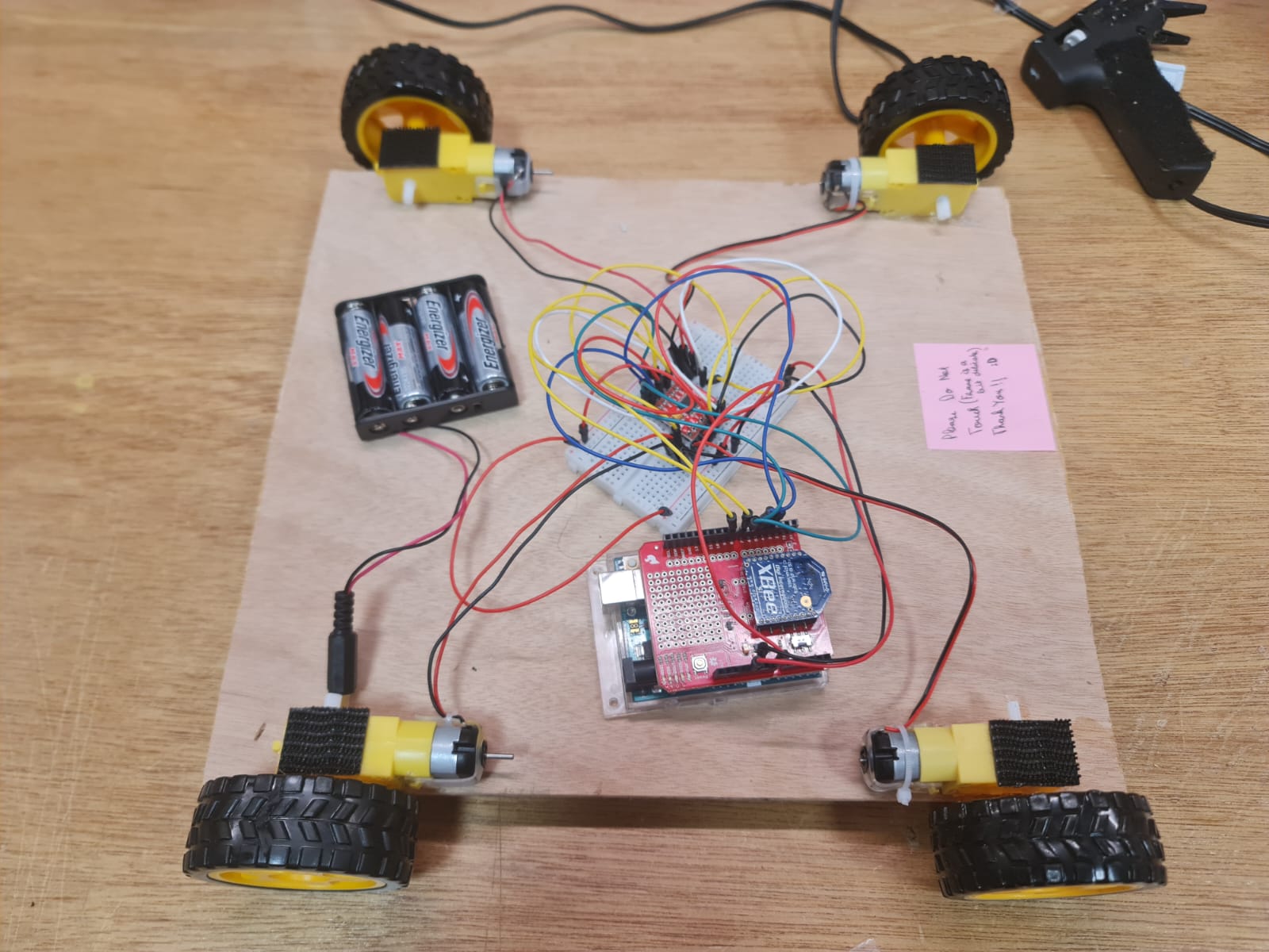 Figuring out power
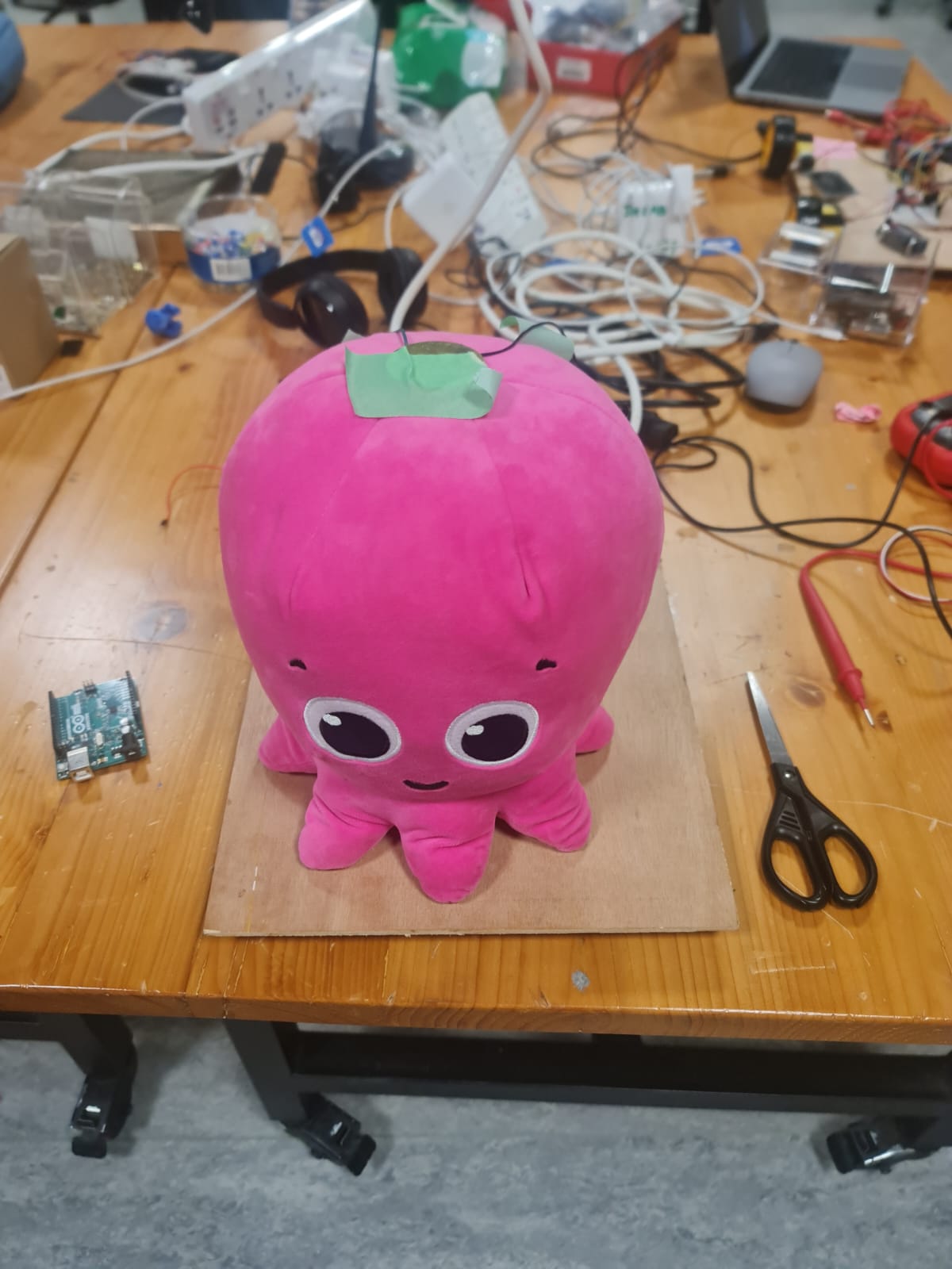 Initial placement
 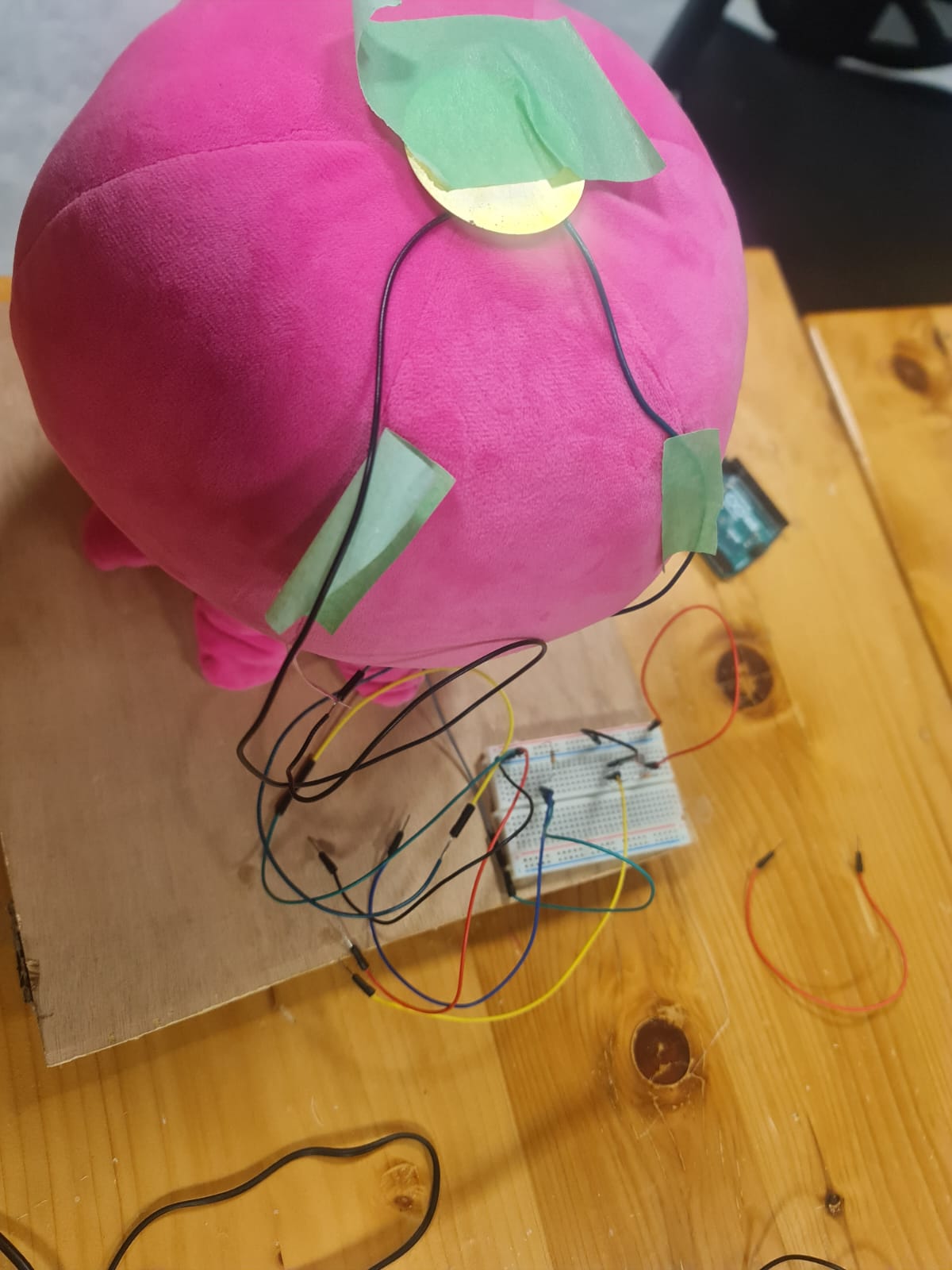 Placement of piezo sensor and photosensor
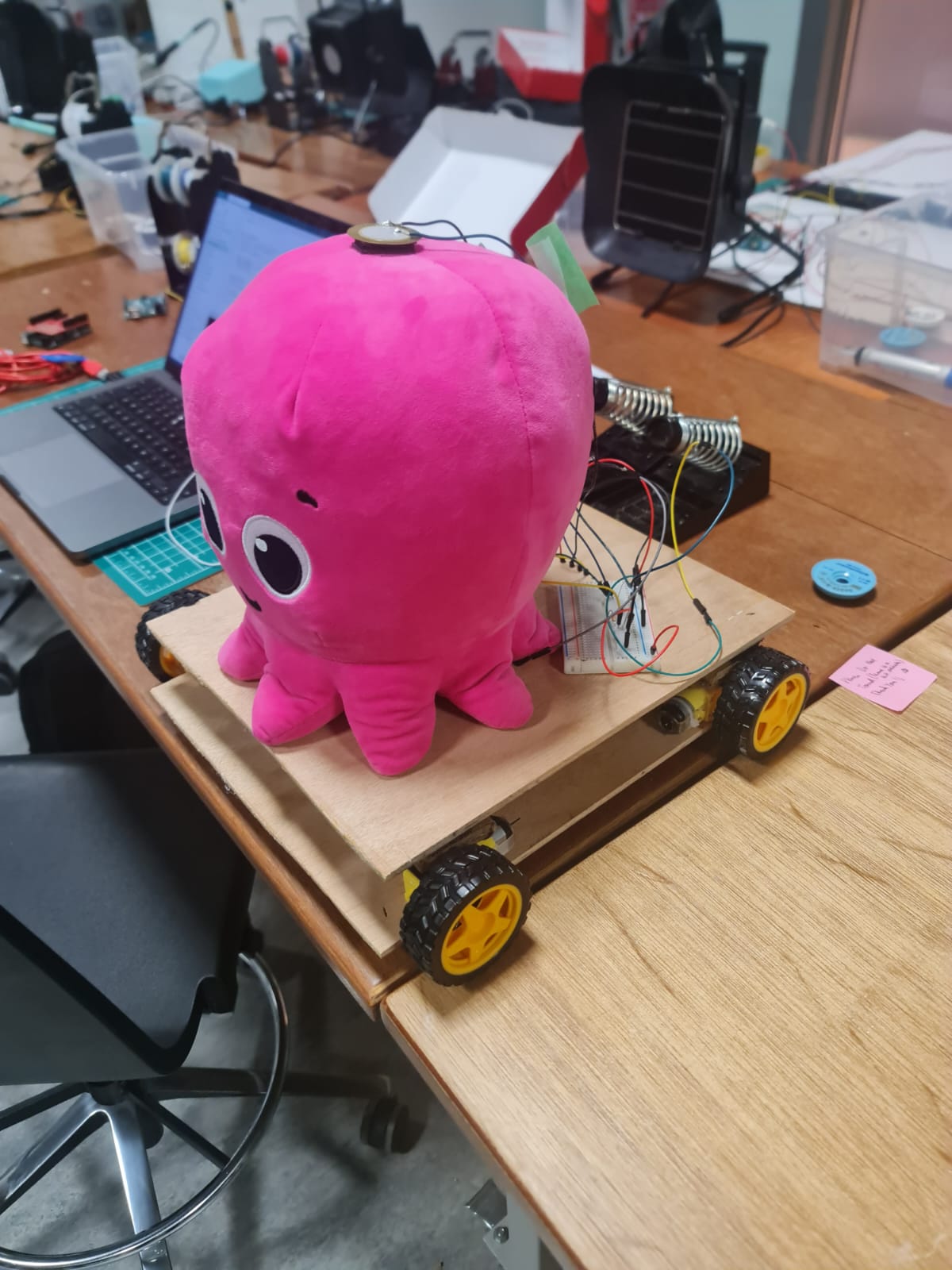 Final placement on top layer
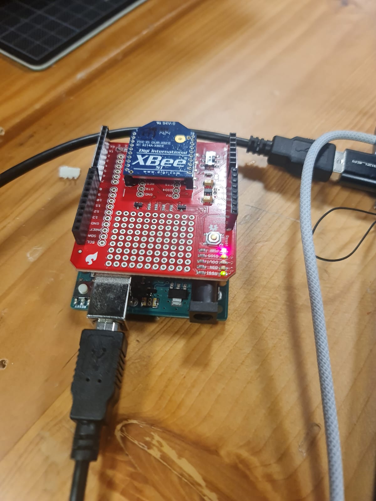 Arduino Board with XBee Shield and XBee Transmitter
 This configuration is important to have everything running