the boulder

  • Describe your concept
  • Include some pictures / video of your project interaction
  • How does the implementation work?
    • Description of interaction design
    • Description of Arduino code and include or link to full Arduino sketch
    • Description of p5.js code and embed p5.js sketch in post
    • Description of communication between Arduino and p5.js
  • What are some aspects of the project that you’re particularly proud of?
  • What are some areas for future improvement?


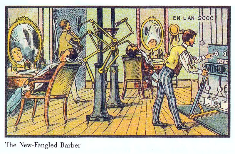
My idea was to creating an art piece using Arduino and p5 that lets user draw pattens on sand, something like this:

I was tempted to change my idea multiple times, because it just seemed too complicated to implement. But I’m glad I stuck with it!

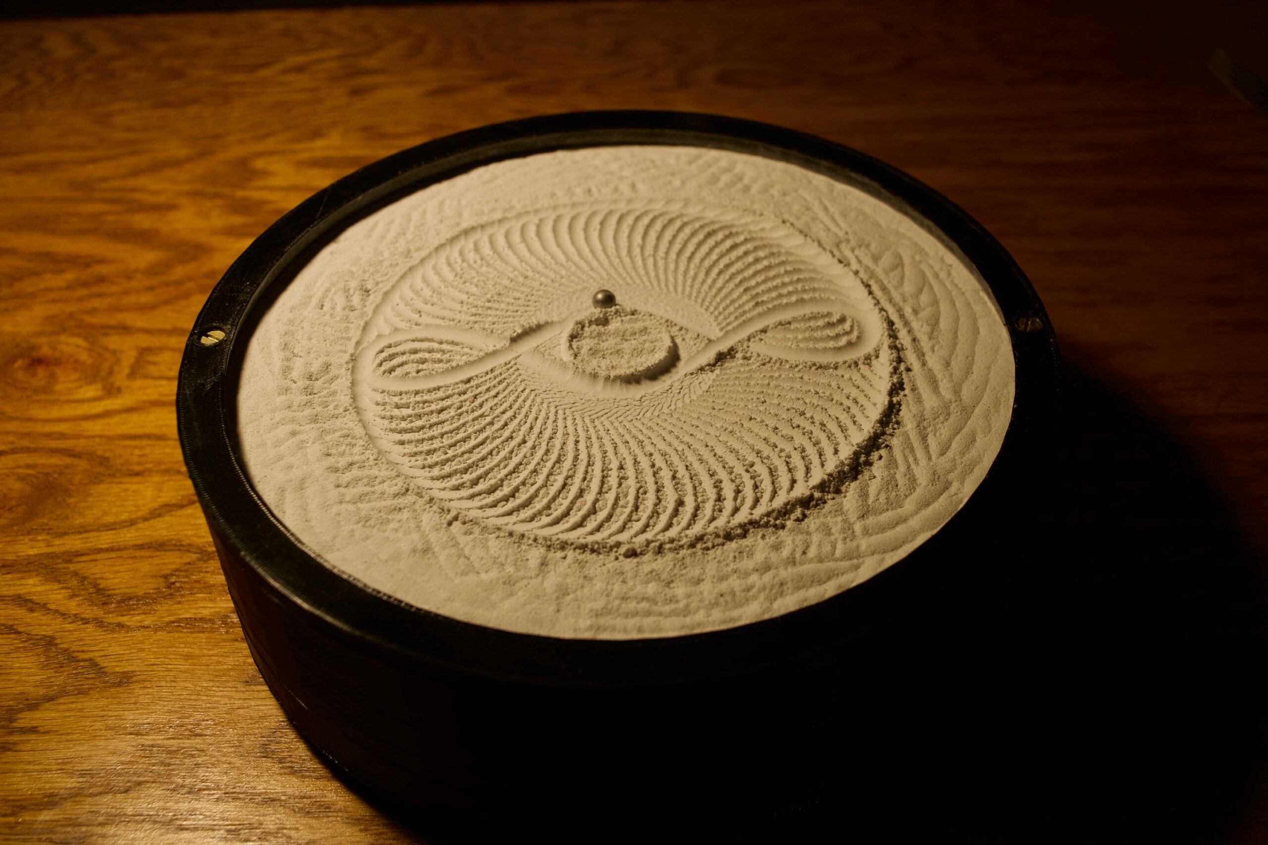
The idea is that there will be something magnetic underneath the platform, hidden from view, and users will be able to move it using an interface. When the magnet underneath the platform moves, the steel ball above will also move with it, leaving patterns on the sand in its wake. In my case, I’ve made a four wheel robot that can go front, back, left, and right.

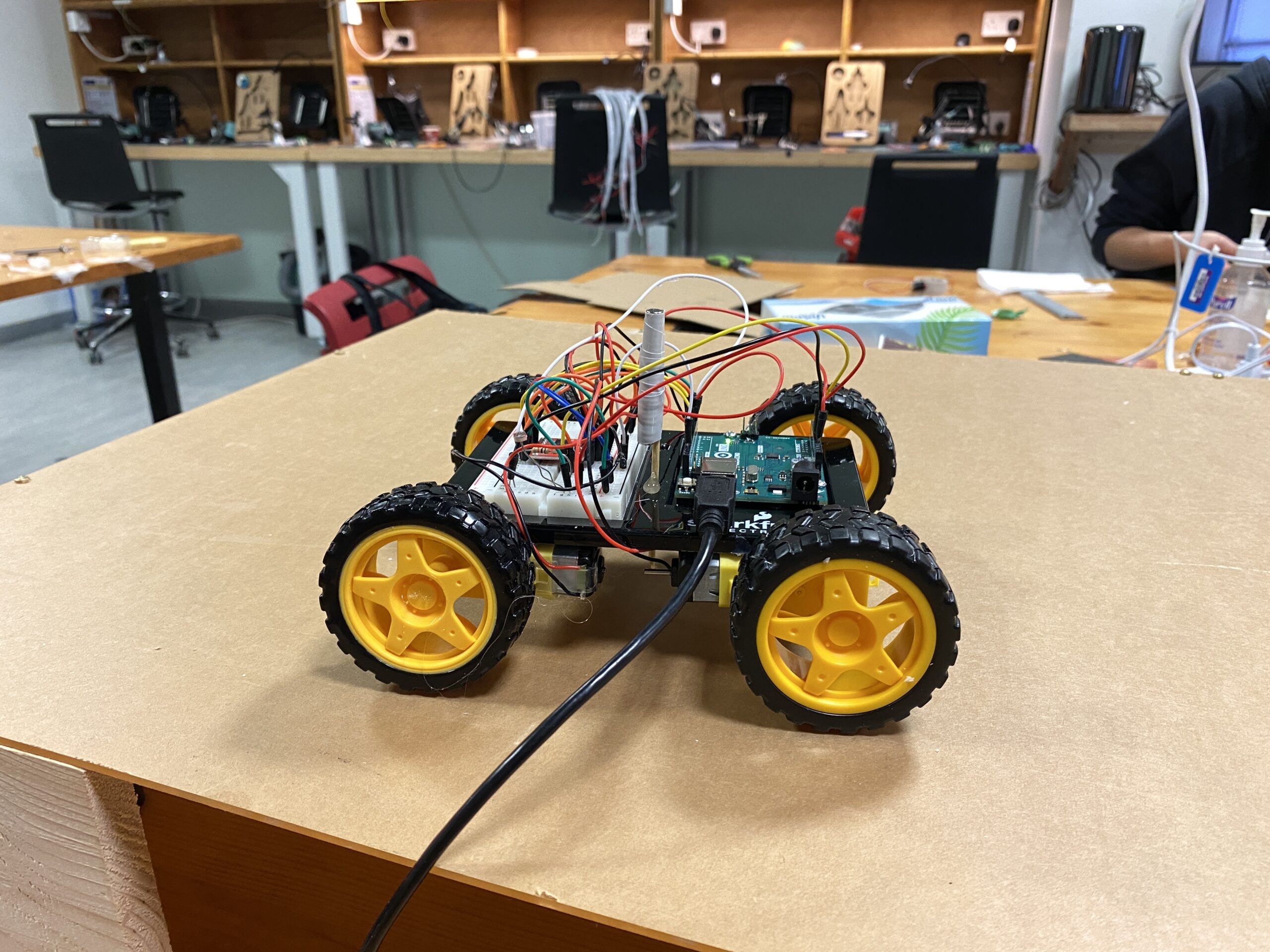
The white thing sticking out of the robot is a stack of magnets, raised to a height just enough to scrape the bottom surface of the platform. Here’s the Arduino code:

const int ain1Pin = 3;
const int ain2Pin = 4;
const int pwmAPin = 5;

const int bin1Pin = 8;
const int bin2Pin = 7;
const int pwmBPin = 6;


void setup() {
  Serial.begin(9600);
  pinMode(ain1Pin, OUTPUT);
  pinMode(ain2Pin, OUTPUT);

  while (Serial.available() <= 0) {
    Serial.println("0,0");
    delay(300);
    digitalWrite(LED_BUILTIN, LOW);
    delay(50);
  }

  // set speed
  analogWrite(pwmAPin, 255);
  analogWrite(pwmBPin, 255);
}

void loop() {
  while (Serial.available()) {
    int left = Serial.parseInt();
    int right = Serial.parseInt();
    if (Serial.read() == '\n') {
      if (left == 1 && right == 0) {
        analogWrite(pwmAPin, 100);
        analogWrite(pwmBPin, 255);
        digitalWrite(ain1Pin, HIGH);
        digitalWrite(ain2Pin, LOW);
        digitalWrite(bin1Pin, HIGH);
        digitalWrite(bin2Pin, LOW);
      }
      if (left == 1 && right == 1) {
        analogWrite(pwmAPin, 255);
        analogWrite(pwmBPin, 255);
        digitalWrite(ain1Pin, HIGH);
        digitalWrite(ain2Pin, LOW);
        digitalWrite(bin1Pin, HIGH);
        digitalWrite(bin2Pin, LOW);
      }
      if (left == 0 && right == 1) {
        analogWrite(pwmAPin, 255);
        analogWrite(pwmBPin, 100);
        digitalWrite(ain1Pin, HIGH);
        digitalWrite(ain2Pin, LOW);
        digitalWrite(bin1Pin, HIGH);
        digitalWrite(bin2Pin, LOW);
      }
      if (left == -1 && right == -1) {
        analogWrite(pwmAPin, 255);
        analogWrite(pwmBPin, 255);
        digitalWrite(ain1Pin, LOW);
        digitalWrite(ain2Pin, HIGH);
        digitalWrite(bin1Pin, LOW);
        digitalWrite(bin2Pin, HIGH);
      } else if (left == 0 && right == 0) {
        digitalWrite(ain1Pin, LOW);
        digitalWrite(ain2Pin, LOW);
        digitalWrite(bin1Pin, LOW);
        digitalWrite(bin2Pin, LOW);
      }
      int sensor = analogRead(A0);
      delay(5);
      int sensor2 = analogRead(A0);
      delay(5);
      Serial.print(sensor);
      Serial.print(',');
      Serial.println(sensor2);
    }
  }
  digitalWrite(LED_BUILTIN, LOW);
}

Front and back motion is fairly simple — all wheels turn at full speed in the same direction. For left and right, I could’ve just made the wheels on one side turn. But I tried this out, and this created strange 360 degree motions. While the robot was turning, the ball on top of the plane wouldn’t move much. This created a strange user experience. So I thought of the velocity differential of each wheel with respect to the other. If the wheel on this side moves faster than the other side, the robot will turn nicely to this side. That’s how real cars work anyway. I ended up going with this logic, and the ball/robot’s motion is now much much smoother.

I was going to just use two wheels on each side. Two motors work fine with Arduino, as we’ve seen in class. In my first prototype, I had only two wheels, that wasn’t enough power, and the robot’s motion was very slow. So I tried to add two more, but it wouldn’t work, even with another motor driver. The Arduino wouldn’t turn on with four motors and two motor drivers connected. I realized that I didn’t need all four wheels to act independently — the front wheels could just imitate the pair at the back, or vice versa. So I plugged in each front wheel in series with the corresponding back wheel, and it worked great!

On the p5.side, things are much simpler. Here’s the link to the full code.

The user can control the robot’s motion by dragging the mouse, and it creates ripples like this:

I wish I could’ve made the magnet attachment better, though. Right now, it’s just taped to a bamboo skewer, stuck into one of the Sparkfun kit baseplates. A better way to do this would be to make an attachment specifically for this purpose.

user testing

I just finished the prototype, so I haven’t added the sand on top of the platform yet. I’ll just add the sand on the day of the showcase.

I asked my friends to try it out, and I think they liked it (refer to the video above). I just told them how to control the robot (with arrow keys for now, just for testing, even though I have the mouse interaction already programmed). I think if I could incorporate a joystick in the project, it would really come together, and also its use would be very intuitive. But without mouse/keyboard input, there wouldn’t be any use for p5.js, so I had to keep it the way it is now.

Sometimes they would drive the ball off the edge of the platform, and so they suggested adding edges to the platform. I think the edges are important anyway because there’s going to be sand, and without edges the sand will just be everywhere.

final project final idea

I’m still sticking to my original idea, but I’ve changed my process considerably. Instead of using pulleys and belts, I’ve just decided to make a raised platform and have a moving robot underneath it. The robot will have a magnet, which will move the ball above the platform. It will make no difference to the user (hopefully), but will make the implementation much easier. I realized I would also need lots of other tools to execute the idea the way I had originally planned, and I’d have to purchase them myself. If I use a moving robot, I can just use the stuff that’s around the lab.

final project proposal

I was building the 3D printer for the lab and noticed how the extruder moves across the X and Y axes. There are two motors, each moving the extruder in one or the other axis. By working both motors together, the extruder can be moved to any X or Y position. This is where I got my final project idea from. I’m going to make a raised tray and fill it with sand, and place one metal ball bearing on the sand surface, like in this picture:

There’s going to be a magnet underneath the table, which attracts the ball, and by moving the magnet, I’ll be able to move the ball on the sand and draw patterns. The magnet is going to be moved across the X and Y axes using two motors, like in the 3D printer. There are a bunch of belts in the IM lab storage, just like the ones that are used in the 3D printer, and I’m hoping that I get to use those for my purposes. If not, I would probably have to order them myself.

This is where p5 comes in: the Arduino controls the motors, but the Arduino is controlled by user input from p5. Users can maybe use keyboard arrows to move a virtual ball on the canvas, and that motion will be replicated by the real ball. I haven’t really pinned down what the user interaction would look like: it could also be users painting with their finger on a touch screen, but the issue with that might be that users might just move their fingers faster than the motors are able to move the ball, so that wouldn’t work. One simple way to tackle this would be to just reduce the frame rate on p5, so that users can’t draw that fast, and the motors are able to keep up.

I would also want to program a “default” mode, so that when there’s no users, the ball draws nice, symmetric shapes on its own. That way, the project could be a nice, standalone art installation, but also interactive.

week 11: reading reflection

The reference to Charles Eames really stuck with me. “Design depends largely on constraints” — I think so too. What is good design if not bad design? It is easy to define bad design. It’s a jumble of elements that do not fit together, but forced into a whole that bears a discordant existence. Good design on the other hand, seems harder to articulate, but what cannot be told can be suggested, which seems to be Pullin’s standpoint as he enters the discussion of designing for special needs. Discretion has been appreciated as a design element when designing for disability, but, on the other hand, in the case of eyewear, there is an existing positive image, and so invisibility is not necessarily a consideration here. This is understandable; that every product has a different context surrounding itself and its design should be in accordance. But then Puliln also says, “fashion can be understated, and discretion does not require invisibility.” The discussion that follows illustrates how several parameters interact in defining the constraints of design, and the design of something transcends the thing itself and blends into people’s perception of other, related concepts, as is in the case of the design of eyewear and fashion.

week 11: class exercise


  1. make something that uses only one sensor  on Arduino and makes the ellipse in p5 move on the horizontal axis, in the middle of the screen, and nothing on arduino is controlled by p5.

I took the existing Arduino and p5 code that we saw in class, and simply added this line in the p5 loop() function:

// move ellipse
ellipse(map(alpha, 0, 1023, 0, 640), width/2, 55, 55);

This allowed me to control the horizontal position of the ellipse by turning the potentiometer.


2. make something that controls the LED brightness from p5Again, starting with the same code, I just made some adjustments. Here’s the relevant part from the p5 code:

if (!serialActive) {
    text("Press Space Bar to select Serial Port", 20, 30);
  } else {
    text("Connected", 20, 30);

    // Print the current values
    text("rVal = " + str(rVal), 20, 50);
    text("alpha = " + str(alpha), 20, 70);
    
    mouseXMapped = map(mouseX, 0, width, 0, 255);
    right = int(mouseXMapped);
    mouseYMapped = map(mouseY, 0, height, 0, 255);
    left = int(mouseYMapped);
  }

This just informs the Arduino of the mouse’s X and Y coordinates.

On the Arduino code, I connected both LEDS to PWM capable ports, and simply added these two lines:

analogWrite(leftLedPin, left);
analogWrite(rightLedPin, right);

The brightness of the left LED increases as the cursor moves to the bottom of the p5 window, and the brightness of the right LED increases as the cursor moves to the right edge of the p5 window.

3. take the gravity wind example (https://editor.p5js.org/aaronsherwood/sketches/I7iQrNCul) and make it so every time the ball bounces one led lights up and then turns off, and you can control the wind from one analog sensorVideo

demo: https://www.youtube.com/shorts/-m7XMTdTVoUI

made the potentiometer control the wind speed (mapped from -1 to 1), and the blue LED blinks whenever the ball comes in contact with the ground. Here’s the complete p5 code, and I left the Arduino code almost untouched, except for a small delay after the LED blinks once, just to make it less jittery.

if (Serial.read() == '\\n') {
      digitalWrite(leftLedPin, left);
      if (left == HIGH) {
        delay (100);
      }
      int sensor = analogRead(A0);
      delay(5);
      int sensor2 = analogRead(A1);
      delay(5);
      Serial.print(sensor);
      Serial.print(',');
      Serial.println(sensor2);
    }


week 10: musical instrument (zion & lukrecija)

Demo:

Concept:

Our idea for the musical instrument was drawn from the classic guitar mechanism. By integrating Light-Dependent Resistors (LDRs) as the sensory input and buzzers as the output, we’ve created a playful experience. Each LDR is strategically positioned to represent a distinct musical note, and when covered, it triggers a corresponding buzzer, simulating the act of plucking strings on a guitar. There’s also a digital switch, which, when pressed, records the notes being played. When the switch is released, the notes are played back.

Items used:

    • Arduino Uno
    • 6 Light-Dependent Resistors (LDRs)
    • 6 Buzzers (Speakers)
    • Resistors (for LDRs )
    • Jumper Wires (for connecting components)
    • 2 Breadboards
    • 1 Momentary Switch

Technical Implementation:

In our musical instrument, each Light-Dependent Resistor (LDR) is assigned to represent a specific musical note, creating a musical sequence reminiscent of a guitar tuning. The choice of notes – E, A, D, G, B, E – corresponds to the standard tuning of the six strings on a guitar. When an LDR is covered, it changes the resistance and triggers the Arduino to interpret this change as a command to play the designated note through the corresponding buzzer.

The Arduino continuously reads the analog values from the LDRs and, upon detecting a significant change, maps the input to trigger the corresponding buzzer connected to a digital output pin. The code is designed to be modular, allowing for easy adjustments to resistor values or the addition of more sensors and buzzers for expanded musical possibilities. 

When the digital switch is pressed, the notes which are played are recorded in an integer array. As soon as the switch is released, the notes in the array are played back using the regular tone() function. 

 // check recording state

 if (digitalRead(SWITCH_PIN) == HIGH) {

   Serial.println("Recording");

   recordMode = true;

 } else if (digitalRead(SWITCH_PIN) == LOW) {

   if (noteCount > 0) {

     Serial.println("Playback");

     recordMode = false;

     for (int i = 0; i < noteCount; i++) {

       tone(playback_PIN, melody[i]);

       delay(200);

     }

     noTone(playback_PIN);

     noteCount = 0;

   }

 }

Future Improvements:

The array can only hold a maximum of 50 notes, and a future improvement could be adding some warning (LED flashing?) to indicate that the array capacity has been reached. There’s also no error handling at this stage, so there could be some unexpected errors if more than 50 notes are recorded.


reading reflection: week 10

First, I should make a point of saying that I have always believed writing to be conversational. When you write something, you open a conversation that remains unfinished business until you’ve heard back from your readers. I understand that this is not how a lot of people see the position of a writer, but it’s just my view, and I’ve lived by it ( — that’s why I’ve emailed all kinds of authors from John Green to Noam Chomsky). So, when I opened the second link under this week’s readings, I was pleasantly surprised to see an author continuing the conversation with his readers, in his humorous but not really condescending tone, which I appreciated very much.

Either way, maybe the author won me over with his jokes, but I feel inclined to agree more with him that with his critics. I have long harbored a slight distaste for VR/AR technologies, but I could never put a finger on where it was coming from. But the author’s “rant” offered the words I was looking for: this obsession with Pictures Under Glass genre of technology feels like a disservice to the human glory. They simply do not engage the full potential for interaction that humans possess, and by being such limited creations, they fall short of being tools that “fit the person”. It’s like giving a lumberjack a butterknife to chop down a tree. The lumberjack will probably just do his job with the knife because that’s all he has, but the creators in his society owe it to him that they start thinking in the general direction of a chainsaw instead of how to make the butter knife more aerodynamic. Simply because the lumberjack is capable of so much more.

I can’t trace how we ended up here, though. There are paintings from the year 1900 predicting how life in the 21st century would look like. Just a few generations ago, people were expecting so much more than just thin LCDs or holographic interaction panels. But somehow, someone along the way popularized these so called Pictures Under Glass technologies, and now we’re in this strange limbo.


There’s this short film from 1967, called 1999 A.D., which shows the life of a family in the future. It predicted many of the things that we have today: cell phones, email, and online shopping. However, these technologies are depicted in very different forms than how we know them today. For example, to reply to an electronic mail, the father has to handwrite his response on a machine with a glossy surface to write on. When the mother wants to go shopping, she turns some knobs on her “fingertip shopping” machine and she’s tuned into a real retailer, where a camera automatically scans across items for sale. These predictions are now fun to look at, with the knowledge that specialized, bulky machines for emailing or remote shopping isn’t the most convenient or realistic way to go. Still, it just goes to show that at some point in history, humans did have the vision to create more dynamic mediums of interaction “that we can see, feel, and manipulate,” but it seems that we have since gone astray.

reading reflection: week 9

Making Interactive Art: Set the Stage, Then Shut Up and Listen reads like meta commentary for this class. For all the work that we have done in the past weeks, we’ve produced supporting documentation backing our inspiration, thought process, methodology, and everything in between. The author speaks of such artists with disdain. “They pre-script what will happen. When you do that, you’re telling the participant what to think, and by extension, how to act. Is that what you wanted?” That is actually not what I want, and for my final project, I would like to work on this author’s terms. I don’t have an idea for my final project yet, but I think I want to create something expansive; something that houses at least the potential for serendipity. The projects that I am making right now are rather limited in functionality, so essentially I have already defined the scope for interactivity before the first interaction with my projects can even happen. But my goal for my final project is to design, for each individual user, unique experiences which exist in a larger permutative space.

The other reading offers some good ideas for thinking in this direction. Furthermore, even though most of the works listed are popular project ideas in the interactive art community, I liked how the author addressed this at the get-go. “So if you’re new to physical computing and thinking to yourself “I don’t want do to that, it’s already done,” stop thinking that way! There’s a lot you can add to these themes through your variation on them.” Usually, when I’m looking for inspiration on the blog for my weekly projects, I look at other people’s work and immediately close off ideas pertaining to the use of similar tools or methods. But looking at projects that use “body-as-cursor” or “hand-as-cursor”, it seems I don’t have to be that restrictive in my thinking. Everyone used Javascript to create all these cool projects in the first half of the semester — but every project came out so unique and with the emblem of each person’s individuality. So, if I see someone using an LDR for their project, I don’t think I should turn away from using LDRs in my project altogether. I can also probably make something cool with the same tools.

week 9: analog/digital

My project this week is fairly simple, and my goal was to just get more comfortable using the components with the Arduino (in preparation for following weeks!). I used an RGB LED controlled by a potentiometer, and a regular LED controlled by a momentary switch to do a little light show.

The RGB LED shines red, green, and blue continuously, but the speed is controlled by the voltage at the potentiometer. The mapping is done as such:

delayTime = map(analogRead(potentiometerPin), 0, 1023, 1, 10);
The other LED is always on. When the switch is pressed, it just turns off.
Here’s a little video demo:

One of the challenges was working with the delay() function for the RGB led, while asking the code to do other things, such as reading the potentiometer value. I was going to use the trick for calculating time, so the delay() function wouldn’t block the rest of the program, or even use a library I found for creating a non blocking timer. But I figured that wasn’t the point of this assignment, so I stuck with delay(). This led to some repetition in my code, and I would definitely not do it this way if I wanted cleaner, more robust code.