Concept
For my final project, I made an interactive mood lamp with five push-buttons corresponding to five moods: Day, Calm, Study, Energetic, and Night. Each mood lights up with a matching color on the arduino and p5, as well as background music from p5.
Implementation
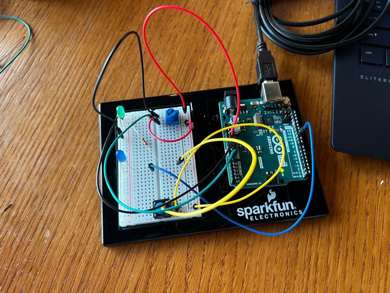
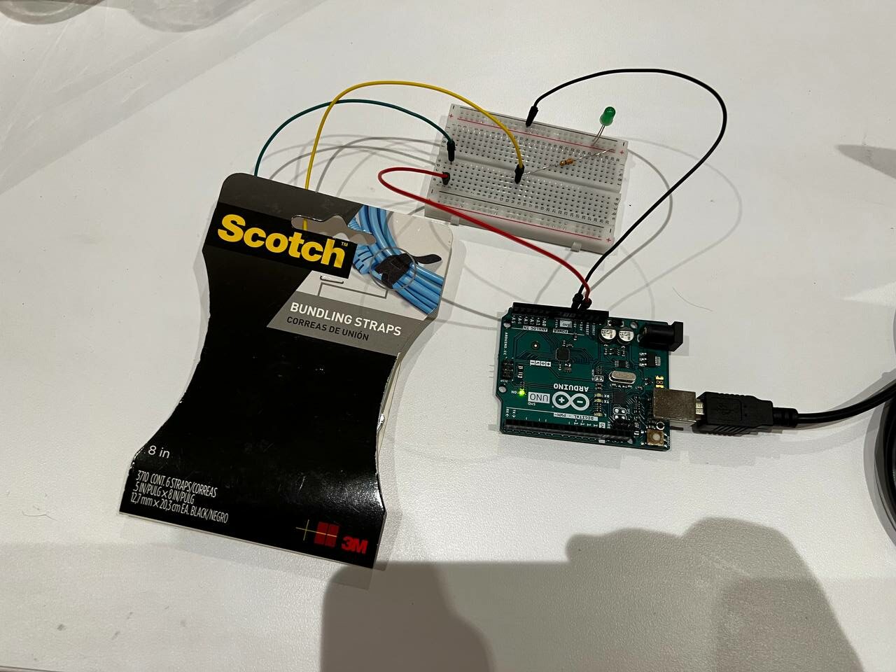
I used a total of 5 push-buttons (obtained from the IM Lab), each for one of the moods. I also used a potentiometer to control the light brightness, an RGB LED for the light itself, and some 220ohm resistors I had at home (because I lost the ones from the kit), as well as the breadboard and jumper wires.
Each button is connected to one of the arduino’s digital ports; I used the internal pullup resistors for them to reduce the amount of components needed and to make the circuit simpler. The RGB LED is connected through resistors to PWM ports to have control over the brightness. The potentiometer is connected to an analog input.
When the arduino starts, the light is set to orange as a starting color, with a matching screen on p5 prompting the user to select a mood. Whenever any of the five buttons are pressed, the light switches to that mood’s color, as well as the p5 screen, and matching music is played. Light brightness can be controlled continuously through the potentiometer.
Arduino Code
// Pin definitions for buttons
const int greenButtonPin = 2;
const int redButtonPin = 4;
const int blueButtonPin = 7;
const int whiteButtonPin = 5;
const int blackButtonPin = 6;

// Pin definitions for RGB LED
const int redLEDPin = 9;
const int greenLEDPin = 10;
const int blueLEDPin = 11;

// Pin definition for the potentiometer
const int potPin = A0;

// Variable to store the last pressed button
int lastPressedButton = 0;

// Current color variables (Default set to orange)
int currentRed = 255;
int currentGreen = 50;
int currentBlue = 0;

void setup() {
  Serial.begin(9600);

  // Initialize button pins
  pinMode(greenButtonPin, INPUT_PULLUP);
  pinMode(redButtonPin, INPUT_PULLUP);
  pinMode(blueButtonPin, INPUT_PULLUP);
  pinMode(whiteButtonPin, INPUT_PULLUP);
  pinMode(blackButtonPin, INPUT_PULLUP);

  // Initialize RGB LED pins
  pinMode(redLEDPin, OUTPUT);
  pinMode(greenLEDPin, OUTPUT);
  pinMode(blueLEDPin, OUTPUT);

  // Set initial LED color and brightness to maximum
  updateBrightness(255); // Ensure full brightness on startup
  setColor(currentRed, currentGreen, currentBlue); // Start with default mood 'Start' (Orange)
  Serial.println("Start");
}

void loop() {
  // Continuously adjust the brightness based on potentiometer reading
  int brightness = analogRead(potPin) / 4; // Scale to 0-255
  updateBrightness(brightness);

  // Check each button and change the LED color and print the mood if changed
  checkButton(greenButtonPin, "Study", 0, 255, 0);
  checkButton(redButtonPin, "Energetic", 255, 0, 0);
  checkButton(blueButtonPin, "Calm", 0, 0, 255);
  checkButton(whiteButtonPin, "Day", 255, 255, 255);
  checkButton(blackButtonPin, "Night", 128, 0, 128);
}

void setColor(int red, int green, int blue) {
  // Store the current color settings
  currentRed = red;
  currentGreen = green;
  currentBlue = blue;
}

void updateBrightness(int brightness) {
  // Adjust the PWM output to LED pins based on the current color and new brightness
  analogWrite(redLEDPin, map(currentRed, 0, 255, 0, brightness));
  analogWrite(greenLEDPin, map(currentGreen, 0, 255, 0, brightness));
  analogWrite(blueLEDPin, map(currentBlue, 0, 255, 0, brightness));
}

void checkButton(int buttonPin, String mood, int red, int green, int blue) {
  if (digitalRead(buttonPin) == LOW && lastPressedButton != buttonPin) {
    delay(50); // Debounce delay
    if (digitalRead(buttonPin) == LOW) { // Confirm the button is still pressed
      lastPressedButton = buttonPin;
      setColor(red, green, blue);
      updateBrightness(analogRead(potPin) / 4); // Update brightness immediately with new color
      Serial.println(mood);
    }
  }
}
Basically, whenever a button corresponding to a mood other than the current one is clicked, the LED color is updated to the color corresponding to the new mood and the mood name is sent to P5 over serial communication. Additionally, the LED brightness is being continuously updated based on changes to the reading from the potentiometer.
P5 Code
let bgColor = [255, 165, 0]; // Orange Starting Color
let moodText = "Mood Lamp"; // Default text to display
let mood = "Start"

// Music Variables
let dayMusic;
let calmMusic;
let studyMusic;
let energeticMusic;
let nightMusic;

// Load all audio
function preload() {
  dayMusic = loadSound('Wii Sports - Title (HQ).mp3');
  calmMusic = loadSound('Animal Crossing New Leaf Music - Main Theme.mp3');
  studyMusic = loadSound('Gusty Garden Galaxy Theme - Super Mario Galaxy.mp3');
  energeticMusic = loadSound('Title Screen - Mario Kart Wii.mp3');
  nightMusic = loadSound('Luma - Super Mario Galaxy.mp3');
}

// Setup canvas
function setup() {
  createCanvas(windowWidth, windowHeight);
  textSize(32);
  textAlign(CENTER, CENTER);
}

function draw() {
  background(bgColor);
  fill(255);
  text(moodText, width / 2, height / 2);

  if (!serialActive) {
    text("Click the screen to select Serial Port", width / 2, height / 2+50)
  }
  else if (mood == "Start") {
    bgColor = [255, 165, 0];
    moodText = "Select one of the mood buttons to being...";
    dayMusic.stop();
    calmMusic.stop();
    studyMusic.stop();
    energeticMusic.stop();
    nightMusic.stop();
  }

  if (mood == "Day") {
    bgColor = [200, 200, 200];
    moodText = mood;
    calmMusic.stop();
    studyMusic.stop();
    energeticMusic.stop();
    nightMusic.stop();
    if (!dayMusic.isPlaying()) dayMusic.loop();
  }

  if (mood == "Calm") {
    bgColor = [0, 0, 255];
    moodText = mood;
    dayMusic.stop();
    studyMusic.stop();
    energeticMusic.stop();
    nightMusic.stop();
    if (!calmMusic.isPlaying()) calmMusic.loop();
  }

  if (mood == "Study") {
    bgColor = [0, 255, 0];
    moodText = mood;
    calmMusic.stop();
    dayMusic.stop();
    energeticMusic.stop();
    nightMusic.stop();
    if (!studyMusic.isPlaying()) studyMusic.loop();
  }

  if (mood == "Energetic") {
    bgColor = [255, 0, 0];
    moodText = mood;
    calmMusic.stop();
    dayMusic.stop();
    studyMusic.stop();
    nightMusic.stop();
    if (!energeticMusic.isPlaying()) energeticMusic.loop();
  }

  if (mood == "Night") {
    bgColor = [128, 0, 128];
    moodText = mood;
    calmMusic.stop();
    dayMusic.stop();
    studyMusic.stop();
    energeticMusic.stop();
    if (!nightMusic.isPlaying()) nightMusic.loop();
  }

}

// Serial code copied from example sketch, with some modifications

function mousePressed() {
  if (!serialActive) {
    // important to have in order to start the serial connection!!
    setUpSerial();
  } else mood = "Start";
}

function readSerial(data) {
  if (data != null) {
    // make sure there is actually a message
    // split the message
    mood = trim(data);
  }
}

function windowResized() {
  resizeCanvas(windowWidth, windowHeight);
}
Basically, after serial connection is established by the user, the canvas is updated to reflect the current mood whenever a new mood is read from the arduino on the serial connection, and the corresponding audio plays as well.
P5 Embedded
User Testing
I had each of my sisters my project to try (prior to making a case and finalizing it).
My first sister managed to figure it out without any instructions from me, surprisingly even knew which COM port to select. She did not figure out that brightness can be controlled by the potentiometer though.
My other (younger) sister managed the same, but did not know which what to do when the COM port prompt came up. She also did not realize that brightness can be controlled.
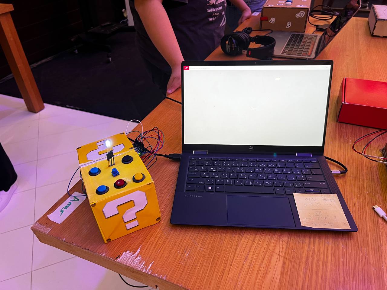
Project Pictures
Project Video
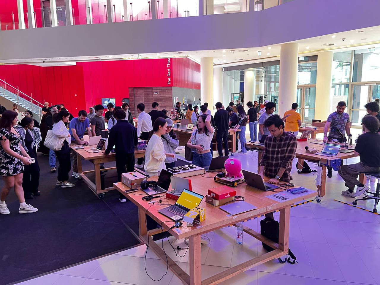
IM Showcase
Problems & Areas for Improvement
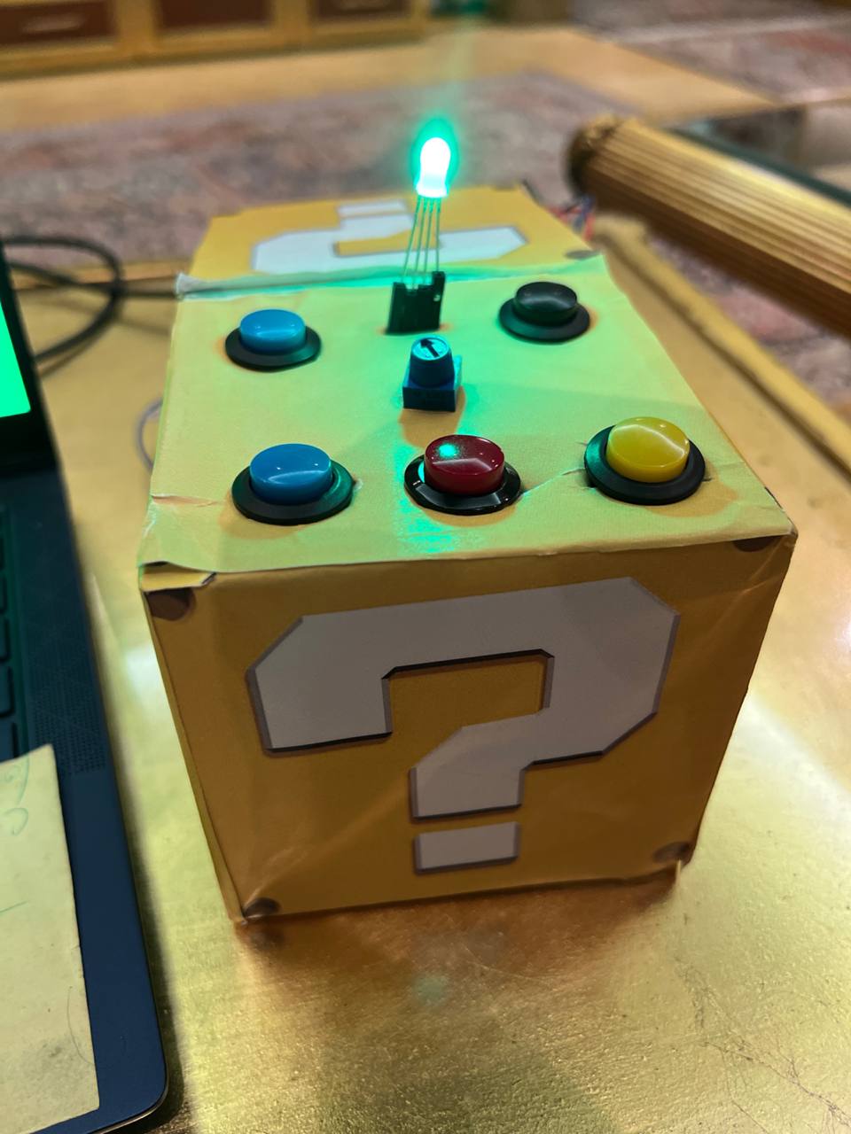
I had built the casing using cardboard I got from Rahaf from Student Affairs. The material is very flimsy and I should replace it with something more permanent and stable. I had to solder wires to the red button immediately before the showcase because it didn’t have any; I also used two blue buttons because I couldn’t find a white one.
Additionally, I could aim to make the project more fun and interactive, but overall it’s a nice idea that people seemed to enjoy at the showcase.