It was pretty exciting to see my roommate and friend dive into the project I’ve been working on. They handled it surprisingly well, navigating through most of it without needing any pointers from me. That’s a good sign that things are intuitive. Most parts of the project seemed to flow smoothly for them, but the joystick part caused a bit of confusion. This is something I would need to focus on especially for those who aren’t familiar with sliding puzzles. I’m sure making that clearer would make it more user-friendly and increase useability. Once I explained the basic instructions—reading the guidelines and hitting the right buttons—they seemed to sail through the rest. Straightforward instructions can really make a difference. There are definitely some areas I want to improve. The shuffling aspect of the puzzle needs tweaking. Sometimes, it gets all twisted up in a way that makes it impossible to solve. It’s on my list of things to work on. Also, those key press functions need fixing. Having to stop and restart the whole thing instead of a simple button press for a restart can be a hassle. So these are things that I am definitely working on for improvement. But overall, I’m pretty proud of where the project stands. It feels good to be at a comfortable point, just needing a few tweaks to make it even better. Excited to keep refining it.
My project concept is one I came to fall in love with. I always liked the idea of taking pictures and so being able to create an interactive environment, where I am able to solve a puzzle using a picture I just took, I think is very fun. This I think is a metaphor for just how challenging but fun this class was. The puzzle could represent some of the challenges I faced throughout the class and building the puzzle represents the way in which my skills developed over the course of the 14 weeks. At the end when you look at the finished puzzle and feel proud of yourself for solving, represents how happy and proud I am of myself, not only to have finished the class, but having done so with new skills and I guess a love for physical computing. I feel like a genius, which is exactly what my LCD screen says when I complete the puzzle.
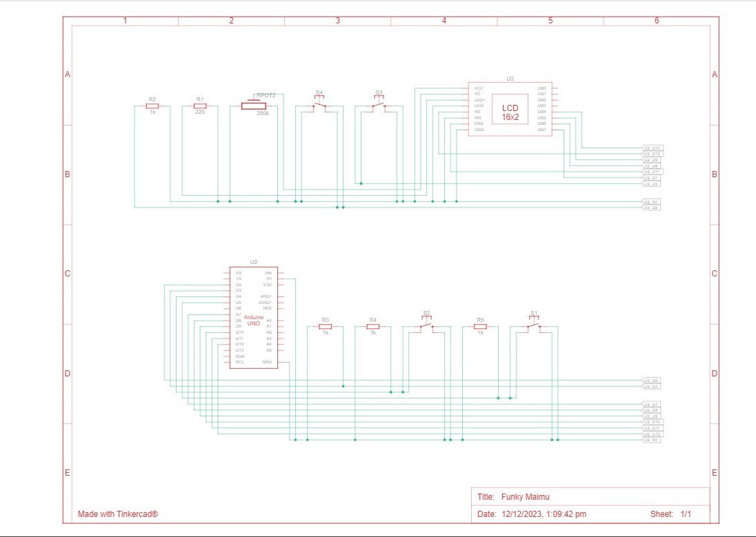
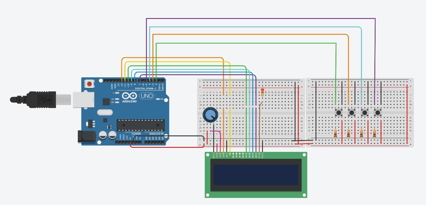
Schematic and Modelling:
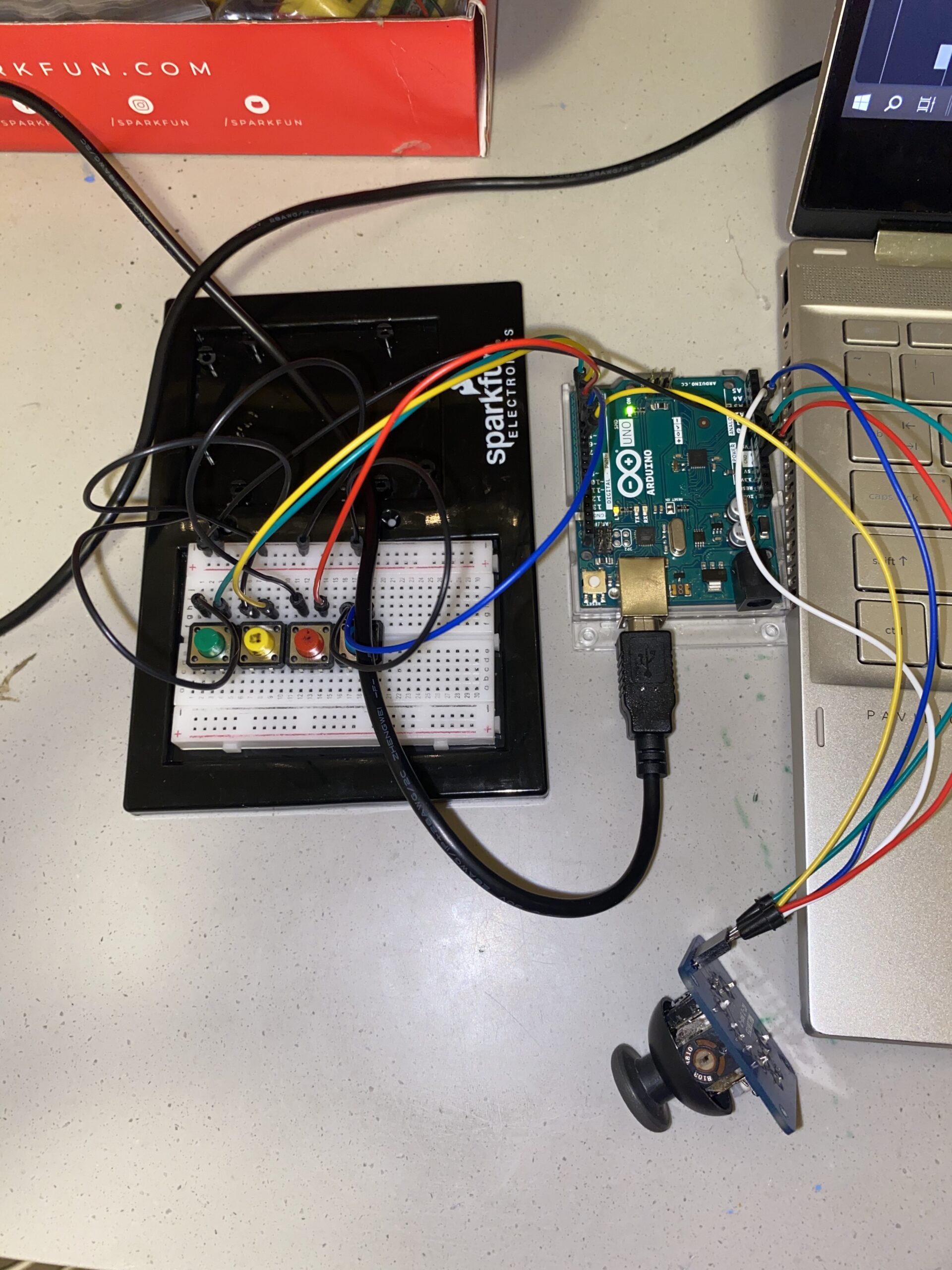
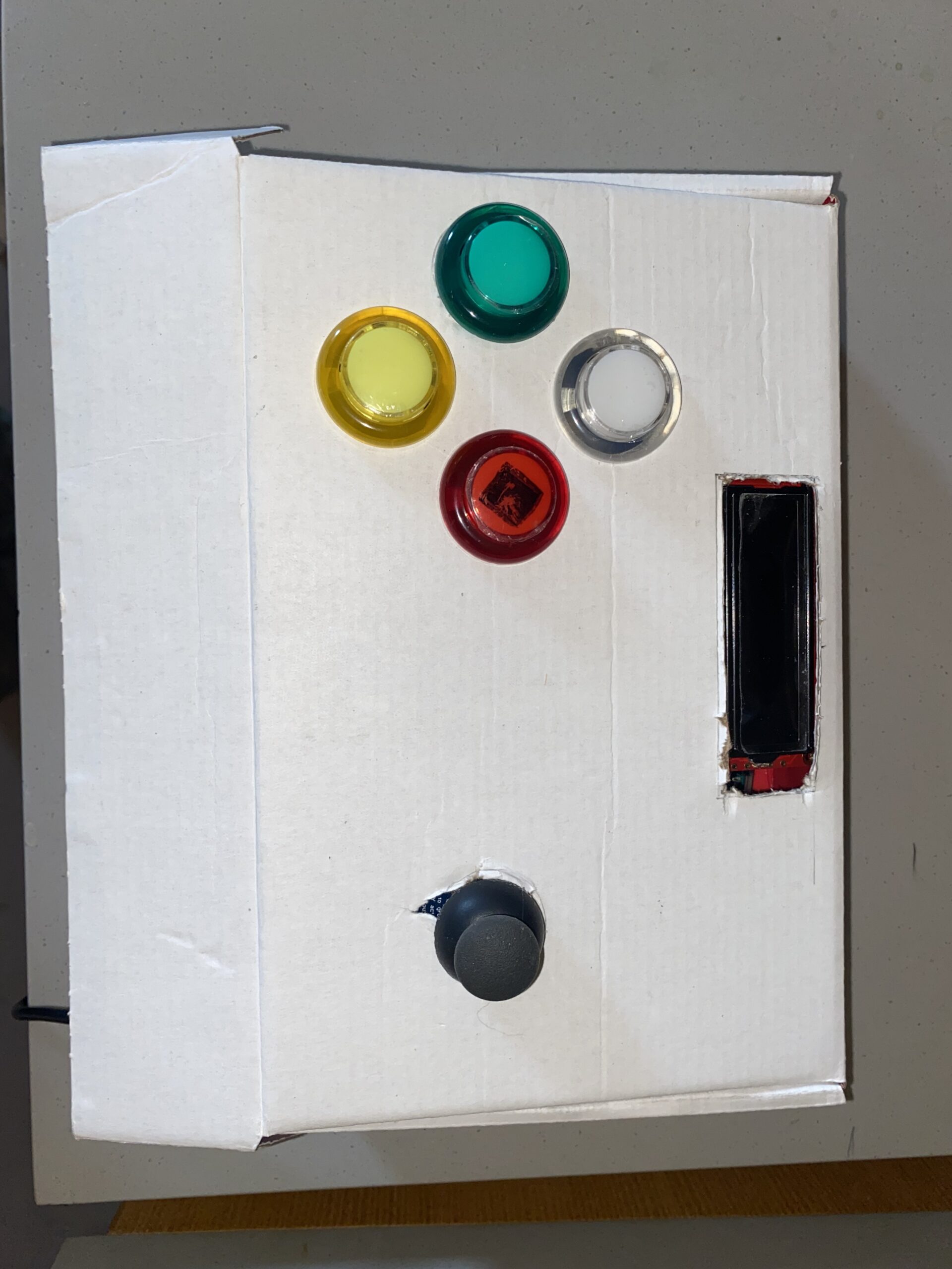
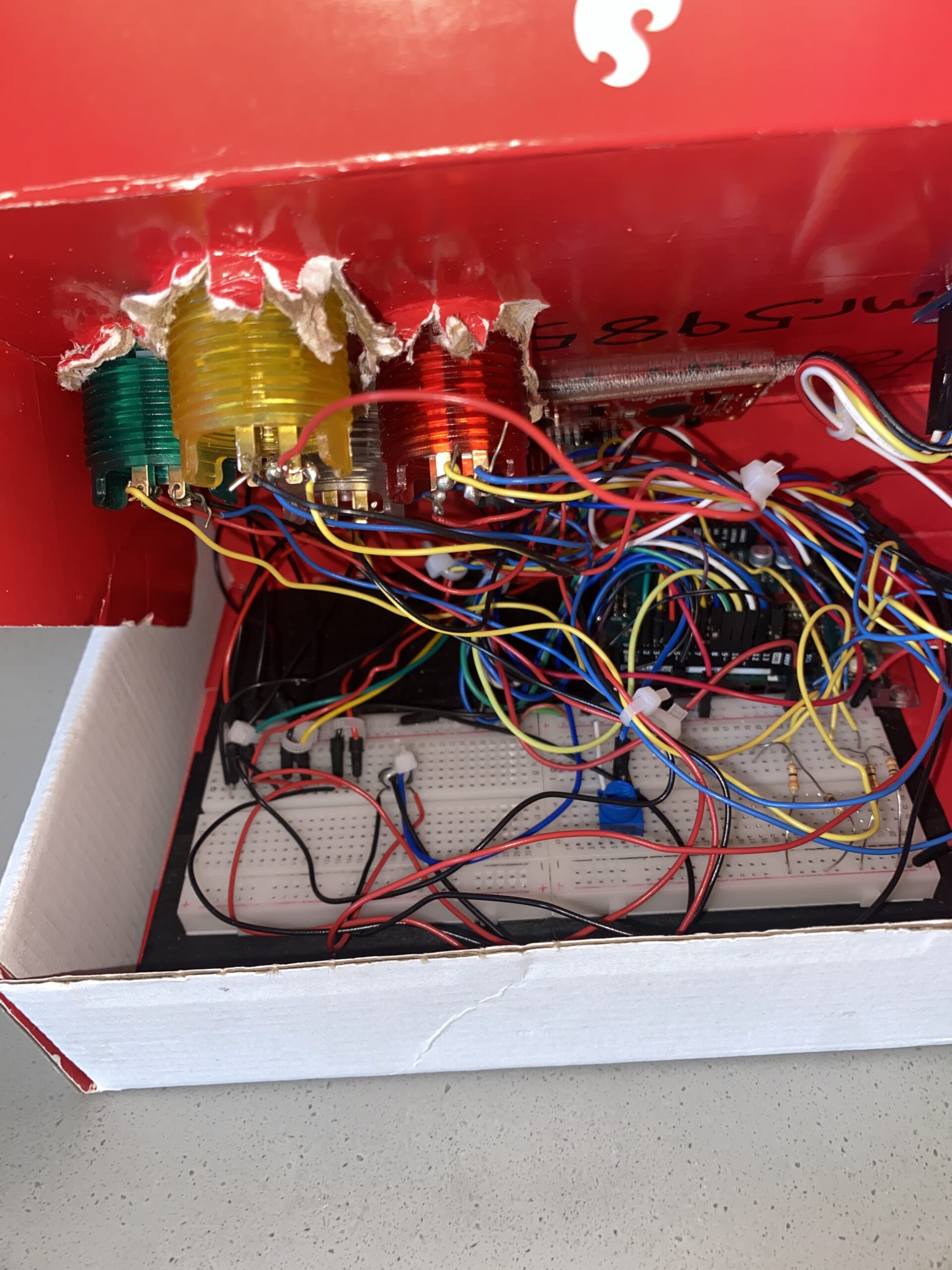
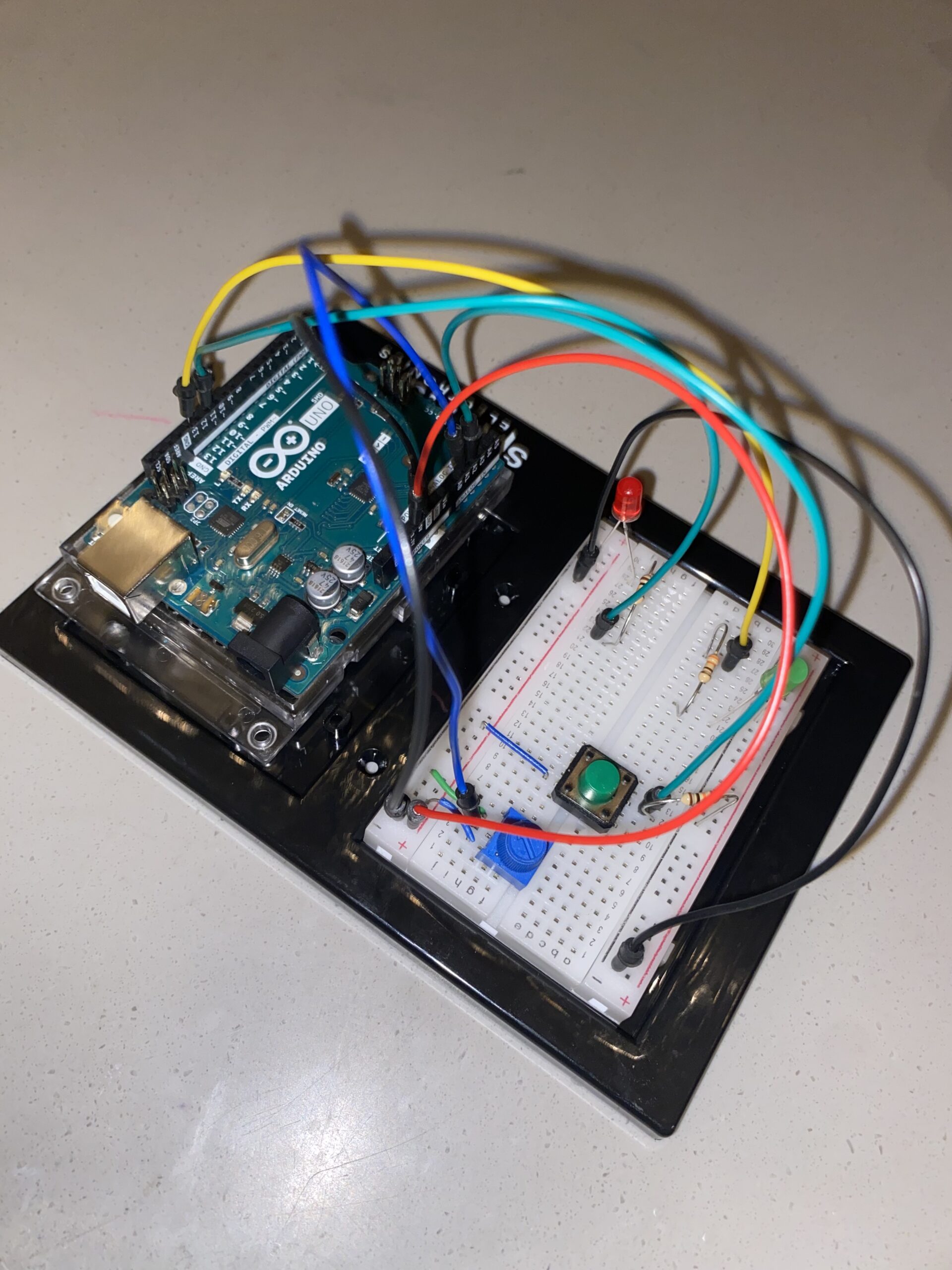
Images of project:
User Testing videos:
How does the implementation work?
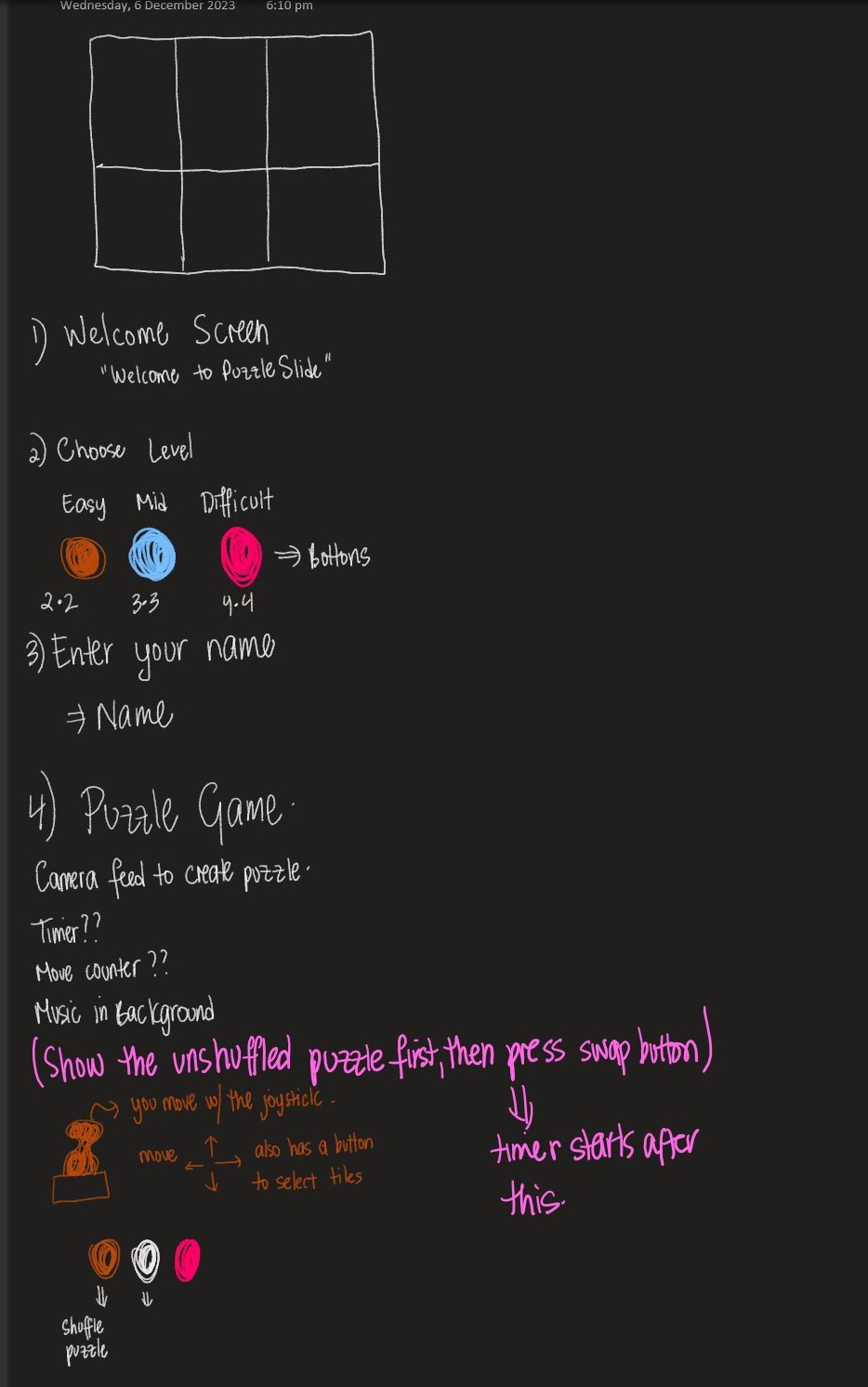
The project’s core idea is straightforward: manipulate the puzzle pieces using the joystick and follow on-screen instructions by pressing the buttons accordingly. The inspiration behind this setup actually came from the PS5 controller. I was dead set on incorporating a joystick into the design, and that sparked the whole concept.
Description of interaction design:
The design is meant to be user-friendly. I aimed for simplicity, assuming everyone knows the basics of a joystick. The on-screen instructions should guide players smoothly through the game. It’s a balance—simple enough for anyone to dive in yet not overly basic to bore them. That’s where the difficulty levels come in. I’ve got three, but I’ve only tested two myself, only managing to crack the first level. Give it a shot and see how far you can go!
Description of Arduino code + code snippets
The Arduino sketch I’ve got sets up a cool interface using buttons and a joystick to handle an LCD display and communicate using serial communication. First off, it gets things going by setting up pins for the buttons and joystick, along with initializing a LiquidCrystal display. The setup() function takes care of configuring serial communication, initializing pins, and prepping the LCD screen. The loop() function takes care of button presses and joystick moves. And when it detects these actions, it sends messages through serial communication. Each action—like a mouse click, difficulty level selection, joystick move, or even a command to snap a picture—is translated into a specific message. This sketch is a great listener too. It keeps an ear out for incoming messages through the serial port. When it gets specific ones like ‘TIMER:’, ‘MOVES:’, or ‘SOLVED’, it updates the LCD screen accordingly. So, you’ll see things like timer values ticking away, move counts racking up, and a sweet congratulatory message popping up when you crack that puzzle.
#include <LiquidCrystal.h>

const int XbuttonPin = 2;
const int SbuttonPin = 3;
const int TbuttonPin = 4;
const int CbuttonPin = 5;
const int joystickXPin = A0; // Analog pin for joystick X-axis
const int joystickYPin = A1; // Analog pin for joystick Y-axis
const int threshold = 50; // Threshold for joystick sensitivity
//bool isDifficulty = false;

LiquidCrystal lcd(6, 12, 11, 10, 9, 8);

void setup() {
  Serial.begin(9600);
  pinMode(XbuttonPin, INPUT_PULLUP);
  pinMode(SbuttonPin, INPUT_PULLUP);
  pinMode(TbuttonPin, INPUT_PULLUP);
  pinMode(CbuttonPin, INPUT_PULLUP);

  lcd.begin(16, 2);
  lcd.clear();
}

void loop() {
  if (digitalRead(XbuttonPin) == LOW) {
    Serial.println("MOUSE_CLICK");
    delay(1000); // Debounce delay
  }

  if (digitalRead(SbuttonPin) == LOW) {
    Serial.println('2');
    delay(100); // Debounce delay
  }

  if (digitalRead(TbuttonPin) == LOW) {
    Serial.println('1');
    delay(1000); // Debounce delay
  }

  if (digitalRead(CbuttonPin) == LOW) {
    Serial.println('3');
    delay(100); // Debounce delay
  }

  if (digitalRead(TbuttonPin) == LOW) {
    Serial.println('C');
    delay(100); // Debounce delay
  }

  int xVal = analogRead(joystickXPin); // Read X-axis value
  int yVal = analogRead(joystickYPin); // Read Y-axis value

  if (xVal < 512 - threshold) {
    Serial.println("LEFT");
    delay(500); // Debounce delay
  } else if (xVal > 512 + threshold) {
    Serial.println("RIGHT");
    delay(500); // Debounce delay
  }

  if (yVal < 512 - threshold) {
    Serial.println("DOWN");
    delay(500); // Debounce delay
  } else if (yVal > 512 + threshold) {
    Serial.println("UP");
    delay(500); // Debounce delay
  }
  if (Serial.available() > 0) {
    String message = Serial.readStringUntil('\n');

    if (message.startsWith("TIMER:")) {
      lcd.setCursor(0, 0);
      lcd.print(message.substring(6)); // Print the timer message
    } else if (message.startsWith("MOVES:")) {
      lcd.setCursor(0, 1);
      lcd.print("Moves: " + message.substring(6)); // Print the move counter message
    } else if (message == "SOLVED") {
      lcd.clear();
      lcd.setCursor(0, 0);
      lcd.print("You are a GENIUS!!!");
      delay(5000); // Display "Puzzle Solved!" for 2 seconds
      lcd.clear();
    }
  }
}
Description of p5.js code + code snippets + embedded sketch
My p5.js puzzle game lets you interact with images, customizable with varying difficulty levels. It progresses through welcome, instructions, and gameplay phases. The Puzzle class manages the game mechanics—moves, shuffling tiles, checking progress, and joystick input. The draw() function orchestrates screens, responding to commands from sources like Arduino. Background music sets the tone for welcome and instructions, fading during gameplay focus. The setup() function initializes the canvas, video feed, and initial puzzle grid, making it the core of this interactive experience.
function captureAndSetupPuzzle(video) {
  if (video) {
    source = video.get();
    source.loadPixels(); // Ensure pixels are loaded
 if (source.width > 0 && source.height > 0) {
    // Resize the source image to fit the canvas
    source.resize(width, height);
    video.hide();

    w = Math.floor(width / cols);
    h = Math.floor(height / rows);

    for (let i = 0; i < cols; i++) {
      for (let j = 0; j < rows; j++) {
        let x = i * w;
        let y = j * h;
        let img = source.get(x, y, w, h); // Get a portion of the image for each tile

        if (i === cols - 1 && j === rows - 1) {
          board.push(-1);
          puzzle.tiles.push(new Tile(-1, img));
        } else {
          let index = i + j * cols;
          board.push(index);
          puzzle.tiles.push(new Tile(index, img));
        }
      }
    }

    puzzle.board = board.slice();
    puzzle.simpleShuffle(puzzle.board);

    currentScreen = 'game';
    puzzle.startTimer();
  } else {
    console.error("Error loading the video source");
    }
  }
}
function joystick(puzzle, direction) {
  let xOffset = (width - puzzle.w * puzzle.cols) / 1.3;
  let yOffset = (height - puzzle.h * puzzle.rows) / 2.5;

  // Calculate the tile indices based on joystick direction
  let i = -1,
    j = -1;
  let blank = puzzle.findBlank();
  let blankCol = blank % puzzle.cols;
  let blankRow = Math.floor(blank / puzzle.rows);

  switch (direction) {
    case 'LEFT':
      i = blankCol + 1;
      j = blankRow;
      moveSound.play();
      break;

    case 'RIGHT':
      i = blankCol - 1;
      j = blankRow;
      moveSound.play();
      break;

    case 'UP':
      i = blankCol;
      j = blankRow + 1;
      moveSound.play();
      break;

    case 'DOWN':
      i = blankCol;
      j = blankRow - 1;
      moveSound.play();
      break;

    default:
      // Handle other cases or unknown commands
      break;
  }

  if (i >= 0 && i < puzzle.cols && j >= 0 && j < puzzle.rows) {
    puzzle.move(i, j, puzzle.board);
  }
  writeSerial("MOVES:" + puzzle.getMoves() + "\n");
 // puzzle.updateTimer(); // Update the timer
 // puzzle.displayTimer(); // Display the timer
}
Description of communication between Arduino and p5.js
In my project, the Arduino and p5.js are like buddies chatting through a USB connection using serial communication. The Arduino sends messages over to p5.js, which eagerly listens and understands what’s being said. Depending on these messages, p5.js swings into action—triggers different functions, or tweaks how the whole thing behaves. It’s like they’re choreographing a dance together! This connection allows the tangible aspects of my project—like button pushes or sensor readings from the Arduino—affect what happens on the digital playground of the p5.js sketch. It’s a smooth back-and-forth: the Arduino talks to p5.js, guiding its moves, while p5.js keeps the Arduino in the loop about how the game’s going—sending updates on moves made and puzzles solved. They’ve got this teamwork thing down, with the Arduino shaking things up in the digital world and p5.js keeping it informed about what’s happening in the game.
What are some aspects of the project that you’re particularly proud of?
One thing I’m really excited about is achieving two-way communication in my project. It was a bit of a hurdle because I’ve always been more comfortable with software like p5.js, which made tasks like controlling mouse clicks and key presses with Arduino a breeze. But the real challenge came when I needed to send information back from p5.js to the Arduino IDE. Figuring out how to establish that connection was a bit tricky, but once I got it working, it felt like a big win.
Another part that I’m super proud of is the capture process. Initially, I had the picture saved and then converted it into the grid. However, I realized this meant that everyone’s picture would end up stored on my laptop, and I wasn’t keen on that idea. So, I reworked the code to immediately convert the picture as soon as it’s taken. I love this feature because it ensures privacy by not saving anyone’s picture on my device, and it’s more immediate and seamless for the users.
One of the toughest parts I tackled was turning the picture into a grid and getting those tiles to shift around. The real challenge here wasn’t just making the picture the puzzle, but doing it on the spot—taking a photo and instantly turning it into a puzzle. It felt like a puzzle itself! For a while, I hit a roadblock. I could snap the picture, form the tiles, but they just wouldn’t budge. Turned out, they weren’t connecting to my puzzle class properly. It was like they were stuck in place. To fix this, I had to dive into the puzzle class and really fine-tune how the capturing worked. It was trial and error, a lot of experimenting. Then, I stumbled upon this function called video() in p5.js, and that was a game-changer. It helped me get things back on track and finally, my project started to click.
Future Work:
I’ve been thinking about how to take this project to the next level and turn it into more of a game. For me, this whole thing has been a way to relax and unwind, not really about competing. But I think adding a competitive element could make it way more interesting. I’ve been considering the idea of making it multiplayer, so that more than one player can get involved in the game. Imagine friends coming together, enjoying some puzzling challenges, and maybe even a bit of friendly competition. It could be a great way for them to hang out and have a good time. By making these changes, I believe it’ll become a fun escape for folks who enjoy puzzles or just want to kick back and have some light-hearted rivalry.
In the true spirit of being a bit indecisive, I’ve opted for a puzzle game. It all started with the certainty that I’d be dealing with a joystick in my physical computing adventures. So, brainstorming around this joystick, the idea of a picture puzzle game struck me. The concept is simple: solve the puzzle using the joystick. To add a personal touch, I thought it’d be cool to let players use their own pictures for the puzzle. I mean, puzzles can be dull, right? So, why not make it more fun by solving a puzzle of yourself?
P5.js Code:
I’ve made some progress in coding the game using P5.js. The groundwork includes screens for welcoming players, providing instructions, selecting difficulty levels, activating the camera, and of course, the puzzle screen itself. The code varies in complexity since it’s still a work in progress. Here’s a snippet that deals with turning a captured picture into a puzzle, which excites me the most.
function captureAndSetupPuzzle(video) {
  if (video) {
    source = video.get();
    source.loadPixels(); // Ensure pixels are loaded
 if (source.width > 0 && source.height > 0) {
    // Resize the source image to fit the canvas
    source.resize(width, height);
    video.hide();

    w = Math.floor(width / cols);
    h = Math.floor(height / rows);

    for (let i = 0; i < cols; i++) {
      for (let j = 0; j < rows; j++) {
        let x = i * w;
        let y = j * h;
        let img = source.get(x, y, w, h); // Get a portion of the image for each tile

        if (i === cols - 1 && j === rows - 1) {
          board.push(-1);
          puzzle.tiles.push(new Tile(-1, img));
        } else {
          let index = i + j * cols;
          board.push(index);
          puzzle.tiles.push(new Tile(index, img));
        }
      }
    }

    puzzle.board = board.slice();
    puzzle.simpleShuffle(puzzle.board);

    currentScreen = 'game';
    puzzle.startTimer();
  } else {
    console.error("Error loading the video source");
    }
  }
}

function setup() {
  createCanvas(600,400);
  //createCanvas(displayWidth, displayHeight);

  video = createCapture(VIDEO);
  video.size(400, 400);
  video.position(0, 0);
  video.hide();


  let timerDuration ;
  let level;

  puzzle = new Puzzle(cols, rows, timerDuration, level); // Example level: 3x3 grid, 600 seconds timer
}
Arduino Code:
Additionally, I’ve been working on Arduino code. It seems mostly complete for now, though I might tweak it as my P5 code progresses. The aim of this code is to control the button movements and the movements of the puzzle tiles using the joystick.
const int XbuttonPin = 2;
const int SbuttonPin = 3;
const int TbuttonPin = 4;
const int CbuttonPin = 5;
const int joystickXPin = A0; // Analog pin for joystick X-axis
const int joystickYPin = A1; // Analog pin for joystick Y-axis
const int threshold = 50; // Threshold for joystick sensitivity
//bool isDifficulty = false;

void setup() {
  Serial.begin(9600);
  pinMode(XbuttonPin, INPUT_PULLUP);
  pinMode(SbuttonPin, INPUT_PULLUP);
  pinMode(TbuttonPin, INPUT_PULLUP);
  pinMode(CbuttonPin, INPUT_PULLUP);
}

void loop() {
  if (digitalRead(XbuttonPin) == LOW) {
    Serial.println("MOUSE_CLICK");
    delay(1000); // Debounce delay
  }

  if (digitalRead(SbuttonPin) == LOW) {
    Serial.println('2');
    delay(100); // Debounce delay
  }

  if (digitalRead(TbuttonPin) == LOW) {
    Serial.println('1');
    delay(10000); // Debounce delay
  }

  if (digitalRead(CbuttonPin) == LOW) {
    Serial.println('3');
    delay(100); // Debounce delay
  }

  if (digitalRead(TbuttonPin) == LOW) {
    Serial.println('C');
    delay(100); // Debounce delay
  }

  int xVal = analogRead(joystickXPin); // Read X-axis value
  int yVal = analogRead(joystickYPin); // Read Y-axis value

  if (xVal < 512 - threshold) {
    Serial.println("LEFT");
    delay(100); // Debounce delay
  } else if (xVal > 512 + threshold) {
    Serial.println("RIGHT");
    delay(100); // Debounce delay
  }

  if (yVal < 512 - threshold) {
    Serial.println("DOWN");
    delay(100); // Debounce delay
  } else if (yVal > 512 + threshold) {
    Serial.println("UP");
    delay(100); // Debounce delay
  }
}
Challenges popped up, especially when translating mouse movements to joystick actions. Initially, I aimed to use mouse clicks and key presses in my P5.js code, thinking I could easily convert them to buttons and switches. But handling joystick movements, considering up, down, left, and right, turned out more intricate than merely clicking a mouse to move a tile.
Tasks on my to-do list seem endless because, well, I’m a bit of a perfectionist. At the moment, I’m focusing on crafting a case for my Arduino and breadboard. Simultaneously, I’m tirelessly refining my P5 sketch for a more appealing look. Adding background music and possibly turning the puzzle into more of an actual game are ideas I’m mulling over. But for now, this is where I stand in my project. I am also thinking of implementing the LED screen to the sketch that would display a message if the puzzle were solved because I think this would be a nice way to implement the p5 to Arduino communication.
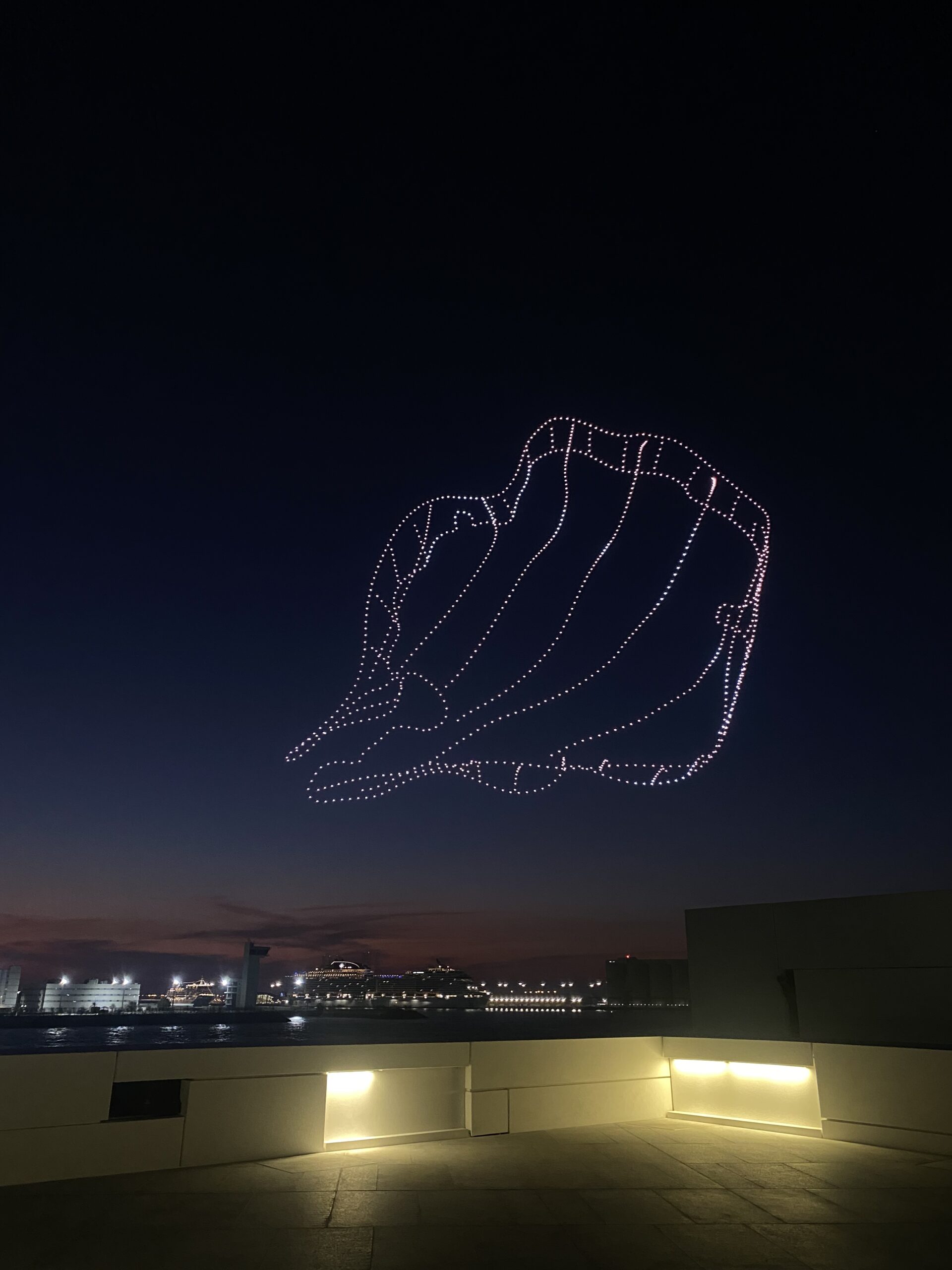
My friend and I visited the Louvre Museum in Abu Dhabi on Sunday. Every night for the entire month, I would see objects lighting up the sky in patterns when I went out late. Upon closer inspection, I quickly discovered that these were drones operating a drone show at the Louvre. But on this specific day, we were positioned on the Louvre terrace, which provided us with the ideal height from which to watch the drone show. After giving it some thought, I’ve decided that this is the theme I want to explore for my final project because we were so close that we could even hear the drones whirring. I’m not sure how I’m going to do it, but I’d like to incorporate this into P5 and have a physical component on Arduino.
Setup:
Your touches on the joystick will translate into a language that the drones can understand thanks to an Arduino Uno and a joystick module. Your motion serves as a cue to them, influencing their formations and flight patterns. The drones will use P5.js as their gateway. The drones would receive commands from Arduino that would essentially give them life and allow their movements to be seen on screen. As the drones fly, every tilt and every movement of the joystick will be reflected in real time.
Interaction:
The user will be interacting with the drones by taking on the role of the conductor and essentially controlling their rhythm, motion, patterns, and position. I want it to feel more like an interactive art experience where you can use P5.js as a canvas and your gestures as the brush, rather than like operating a remote-control car.
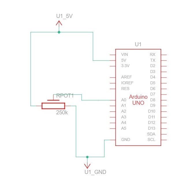
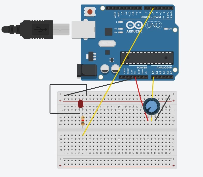
Make something that uses only one sensor on Arduino and makes the ellipse in p5 move on the horizontal axis, in the middle of the screen, and nothing on Arduino is controlled by p5.
SCHEMATIC AND MODELLING:
P5 CODE:
let circleX = 0;
function setup() {
  createCanvas(640, 480);
  textSize(18);
}

function draw() {
  background(255);
  stroke(0);

  fill("pink");
  circle(map(circleX,0, 1023, 0, width), height/2, 50);

  if (!serialActive) {
    text("Press Space Bar to select Serial Port", 20, 30);
  } else {
    text("Connected", 20, 30);
  }

}

function keyPressed() {
  if (key == " ") {
    // important to have in order to start the serial connection!!
    setUpSerial();
  }
}

// This function will be called by the web-serial library
// with each new *line* of data. The serial library reads
// the data until the newline and then gives it to us through
// this callback function
function readSerial(data) {
  ////////////////////////////////////
  //READ FROM ARDUINO HERE
  ////////////////////////////////////

  if (data != null) {
    circleX = int(trim(data));

  }
  print(circleX);
}
ARDUINO CODE:
void setup() {
  // Start serial communication so we can send data
  // over the USB connection to our p5js sketch
  Serial.begin(9600);

  // We'll use the builtin LED as a status output.
  // We can't use the serial monitor since the serial connection is
  // used to communicate to p5js and only one application on the computer
  // can use a serial port at once.
  pinMode(LED_BUILTIN, OUTPUT);

}

void loop() {

  int sensor = analogRead(A0);
  delay(5);
  digitalWrite(LED_BUILTIN, HIGH);
  Serial.println(sensor);

  digitalWrite(LED_BUILTIN,LOW);
}
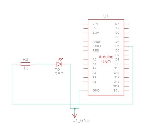
Make something that controls the LED brightness from p5.
SCHEMATIC AND MODELLING:
P5 CODE:
let value = 0;

function setup() {
  createCanvas(640, 480);
  textSize(18);
}

function draw() {
  background(0);
  stroke(255);
  fill(255);

  if (!serialActive) {
    text("Press Space Bar to select Serial Port", 20, 30);
  } else {
    text("Connected", 20, 30);
  }
}

function keyPressed() {
  if (key == " ") {
    // important to have in order to start the serial connection!!
    setUpSerial();
  }
}

// This function will be called by the web-serial library
// with each new *line* of data. The serial library reads
// the data until the newline and then gives it to us through
// this callback function
function readSerial(data) {
  if (data != null) {
    //////////////////////////////////
  //SEND TO ARDUINO HERE (handshake)
  //////////////////////////////////
    value = int(map(mouseX, 0, width, 0, 255));
  let sendToArduino = value + "\n";
  writeSerial(sendToArduino);
  print(value);


  }


}
ARDUINO CODE:
int ledPin = 5;

void setup() {
  // Start serial communication so we can send data
  // over the USB connection to our p5js sketch
  Serial.begin(9600);

  // We'll use the builtin LED as a status output.
  // We can't use the serial monitor since the serial connection is
  // used to communicate to p5js and only one application on the computer
  // can use a serial port at once.
  pinMode(LED_BUILTIN, OUTPUT);
  pinMode(ledPin, OUTPUT);

  digitalWrite(ledPin, HIGH);
  delay(1000);
  digitalWrite(ledPin, LOW);

  // start the handshake
  while (Serial.available() <= 0) {
    digitalWrite(LED_BUILTIN, HIGH); // on/blink while waiting for serial data
    Serial.println("0,0"); // send a starting message
    delay(300);            // wait 1/3 second
    digitalWrite(LED_BUILTIN, LOW);
    delay(50);
  }

}

void loop() {


  // wait for data from p5 before doing something
  while (Serial.available()) {
    Serial.println("0,0");
    digitalWrite(LED_BUILTIN, HIGH); // led on while receiving data

    int value = Serial.parseInt();

    if (Serial.read() == '\n') {
      analogWrite(ledPin, value);
    }
  }
  digitalWrite(LED_BUILTIN, LOW);


}
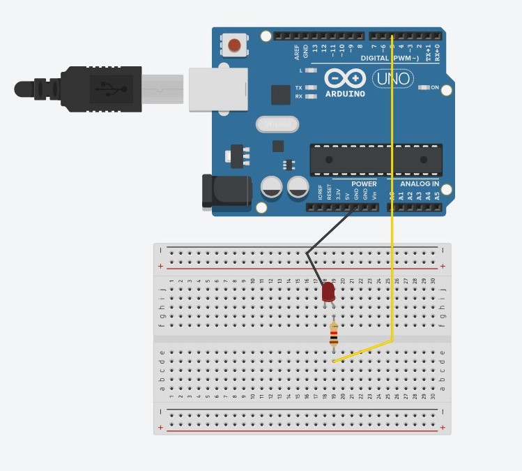
Take the gravity wind example and make it so: every time the ball bounces one led lights up and then turns off, and you can control the wind from one analog sensor.
SCHEMATIC AND MODELLING:
P5 CODE:
let velocity;
let gravity;
let position;
let acceleration;
let wind;
let value = 0;
let drag = 1;
let mass = 50;

function setup() {
  createCanvas(640, 360);
  noFill();
  position = createVector(width/2, 0);
  velocity = createVector(0,0);
  acceleration = createVector(0,0);
  gravity = createVector(0, 0.5*mass);
  wind = createVector(0,0);
}

function draw() {
  background(255);
  stroke(0);
  fill(0);
  if (!serialActive) {
    text("Press Space Bar to select Serial Port", 20, 30);
  } else {
    text("Connected", 20, 30);

    applyForce(wind);
    applyForce(gravity);
    velocity.add(acceleration);
    velocity.mult(drag);
    position.add(velocity);
    acceleration.mult(0);
    ellipse(position.x,position.y,mass,mass);

    if (position.y > height-mass/2) {
        velocity.y *= -0.9;  // A little dampening when hitting the bottom
        position.y = height-mass/2;
        value = 1;
      }
    else {
      value = 0;
    }

  }


}

function applyForce(force){
  // Newton's 2nd law: F = M * A
  // or A = F / M
  let f = p5.Vector.div(force, mass);
  acceleration.add(f);
}

function keyPressed(){

  if (key==UP_ARROW){
    mass=random(15,80);
    position.y=-mass;
    velocity.mult(0);
  }
  if (key == " ") {
    // important to have in order to start the serial connection!!
    setUpSerial();
  }
}


// This function will be called by the web-serial library
// with each new *line* of data. The serial library reads
// the data until the newline and then gives it to us through
// this callback function
function readSerial(data) {
  ////////////////////////////////////
  //READ FROM ARDUINO HERE
  ////////////////////////////////////

  if (data != null) {

    if (int(trim(data)) >= 511) {
      wind.x = 3;
    }
    else {
      wind.x = -3;
    }

    //////////////////////////////////
    //SEND TO ARDUINO HERE (handshake)
    //////////////////////////////////
    let sendToArduino = value + "\n";
    writeSerial(sendToArduino);
  }
}
ARDUINO CODE:
int ledPin = 5;

void setup() {
  // Start serial communication so we can send data
  // over the USB connection to our p5js sketch
  Serial.begin(9600);

  // We'll use the builtin LED as a status output.
  // We can't use the serial monitor since the serial connection is
  // used to communicate to p5js and only one application on the computer
  // can use a serial port at once.
  pinMode(LED_BUILTIN, OUTPUT);
  pinMode(ledPin, OUTPUT);

  // start the handshake
  while (Serial.available() <= 0) {
    digitalWrite(LED_BUILTIN, HIGH); // on/blink while waiting for serial data
    Serial.println("0"); // send a starting message
    delay(300);            // wait 1/3 second
    digitalWrite(LED_BUILTIN, LOW);
    delay(50);
  }

}

void loop() {


  digitalWrite(LED_BUILTIN, LOW);

  // wait for data from p5 before doing something
  while (Serial.available()) {
    digitalWrite(LED_BUILTIN, HIGH); // led on while receiving data

    int value = Serial.parseInt();

    if (Serial.read() == '\n') {
      if (value == 1) {
        digitalWrite(ledPin, HIGH);
      }
      else {
        digitalWrite(ledPin, LOW);
      }

      int sensor = analogRead(A0);
      delay(5);
      Serial.println(sensor);
    }
  }
  digitalWrite(LED_BUILTIN, LOW);


}
Pullin’s “Design Meets Disability” represents a good cross-section between, disability, fashion and design. In my opinion, he presents a story that goes beyond basic usability to embrace the core ideas of inclusion and empowerment, particularly when viewed through the lens of inclusivity and disability. In his book Pullin deftly demonstrates how assistive technology—like glasses, hear wear, and prosthetic limbs (leg wear)—has transformed into fashion statements. It’s amazing to see how design innovation has transformed these items from basic needs to unique expressions of identity and personal style to the point where today, spectacles are a fashion statement, unlike when they were only meant for individuals with disabilities like bad eyesight. Pullin discusses the significance of designs being both functional and aesthetically pleasing. He demonstrates how important it is to make things both visually appealing and accessible to those with disabilities. It’s similar to saying, “Hey, these things can look great AND they can help you!” Pullin emphasizes how a combination of good design and utility may change public perceptions of disability aids, increasing their social acceptance and appreciation.
Pullin discusses how keeping functionality without sacrificing simplicity can benefit those with disabilities. He illustrates how many people, regardless of ability, can profit from this type of design. He provides illustrations of universally usable, basic designs that improve the quality of life for those with impairments. It also emphasizes how crucial it is to pay attention to individuals with disabilities when creating these designs, as frequently we assume we know what is best for them based on presumptions and the stigmas society has attached to them. Therefore, I believe it is crucial to draw attention to these minute details that, not only benefit us but also those who are the primary beneficiaries of these designs.
This reading challenged me to consider creating not just an “interactive” design, but a GOOD interactive design that can improve everyone’s quality of life, particularly for those who are disabled. It’s not only about making things function; it’s also about making them user-friendly, simple and fashionable. I learned that good design considers everyone’s needs and can change how we see and accept things like disability aids. It’s about making the world more inclusive and thoughtful for everyone.
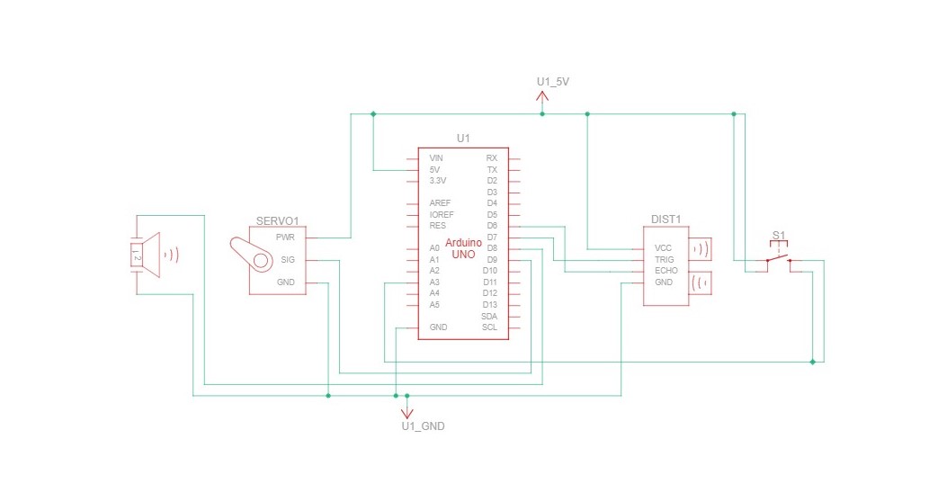
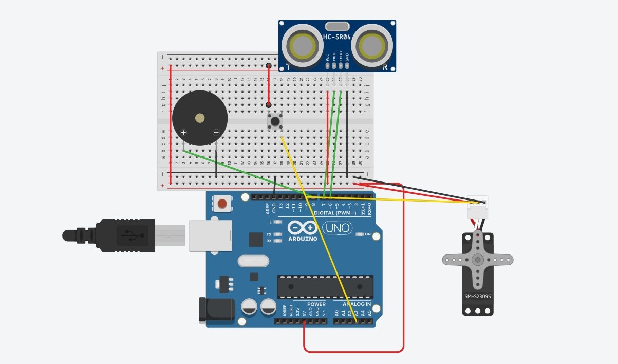
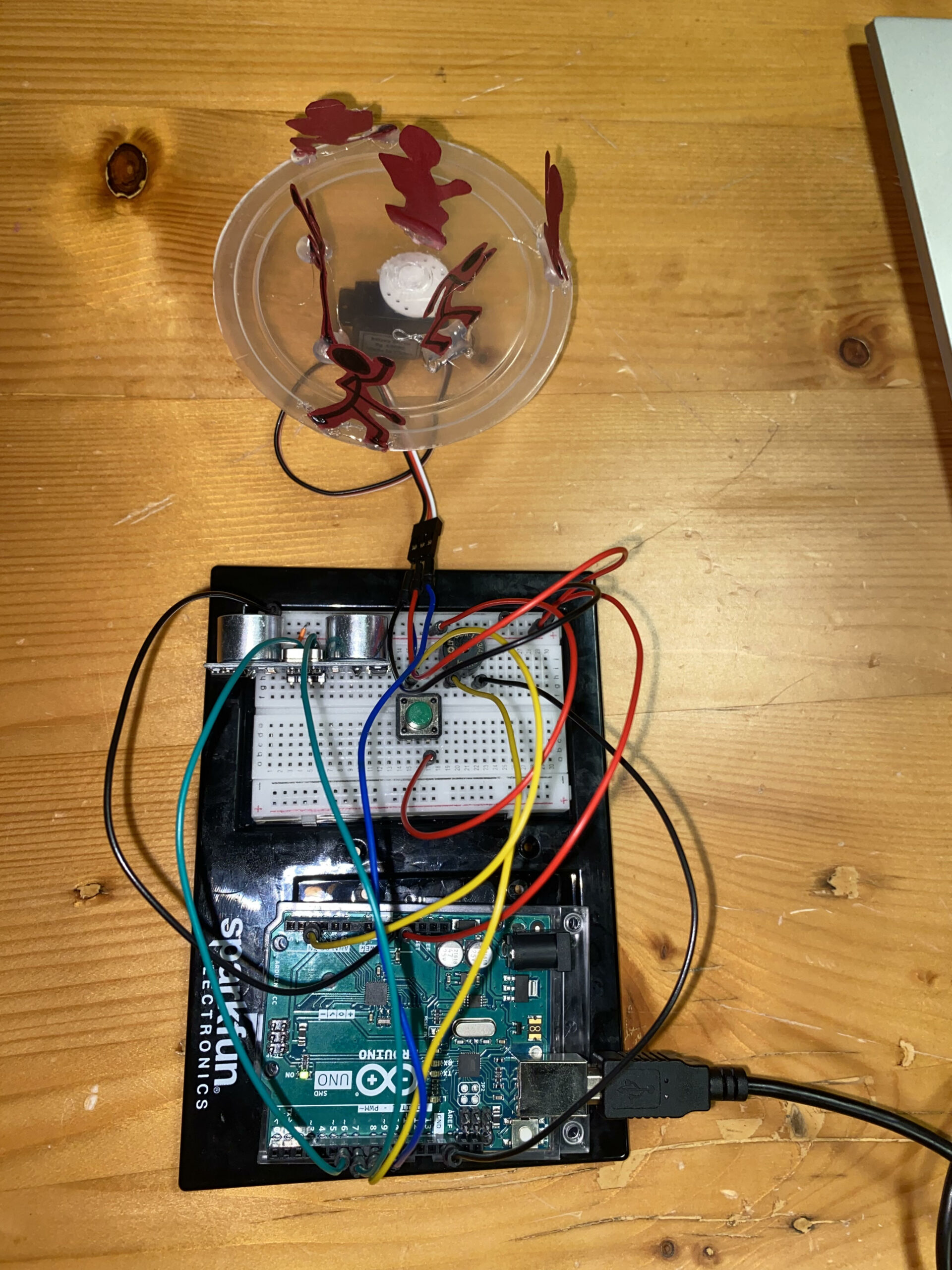
Rujul and I collaborated on our Week 10 assignment, centered on crafting a musical instrument. Our initial concept revolved around utilizing the ultrasonic sensor and piezo speaker to create a responsive system, triggering sounds based on proximity. However, we expanded the idea by incorporating a servo motor to introduce a physical dimension to our instrument. The final concept evolved into a dynamic music box that not only moved but also emitted sound. The servo motor controlled the music box’s rotation, while the ultrasonic sensor detected proximity, prompting different tunes to play. To reset the music box, we integrated a button to return the servo motor to its initial position.
Our prototype took shape seamlessly, and the coding aspect proved relatively straightforward. One particularly intriguing segment involved establishing thresholds for distinct melodies based on the object’s position within the carousel.
void checkDistanceAndSound() {
  int duration, distance;

  digitalWrite(TRIG_PIN, LOW);
  delayMicroseconds(2);
  digitalWrite(TRIG_PIN, HIGH);
  delayMicroseconds(10);
  digitalWrite(TRIG_PIN, LOW);

  duration = pulseIn(ECHO_PIN, HIGH);
  distance = (duration * 0.0343) / 2;

  // Play different melodies for different distance ranges
  if (distance > 0 && distance <= 5 && !soundProduced) {
    playMelody1();
    soundProduced = true;
    delay(2000); // Adjust delay as needed to prevent continuous sound
  } else if (distance > 5 && distance <= 10 && !soundProduced) {
    playMelody2();
    soundProduced = true;
    delay(2000); // Adjust delay as needed to prevent continuous sound
  } else if (distance > 10 && distance <= 20 && !soundProduced) {
    playMelody3();
    soundProduced = true;
    delay(2000); // Adjust delay as needed to prevent continuous sound
  } else {
    noTone(SPEAKER_PIN);
    soundProduced = false;
  }
}

void playMelody1() {
  int melody[] = {262, 294, 330, 349, 392, 440, 494, 523}; // First melody
  int noteDurations[] = {250, 250, 250, 250, 250, 250, 250, 250};

  for (int i = 0; i < 8; i++) {
    tone(SPEAKER_PIN, melody[i], noteDurations[i]);
    delay(noteDurations[i]);
  }
}

void playMelody2() {
  int melody[] = {392, 440, 494, 523, 587, 659, 698, 784}; // Second melody
  int noteDurations[] = {200, 200, 200, 200, 200, 200, 200, 200};

  for (int i = 0; i < 8; i++) {
    tone(SPEAKER_PIN, melody[i], noteDurations[i]);
    delay(noteDurations[i]);
  }
}

void playMelody3() {
  int melody[] = {330, 330, 392, 392, 440, 440, 330, 330}; // Third melody
  int noteDurations[] = {500, 500, 500, 500, 500, 500, 1000, 500};

  for (int i = 0; i < 8; i++) {
    tone(SPEAKER_PIN, melody[i], noteDurations[i]);
    delay(noteDurations[i]);
  }
}
Reflection:
Reflecting on our project, I believe enhancing it with LEDs synchronized to specific sounds could offer a more comprehensive understanding of the ultrasonic sensor’s functionality. Each LED would correspond to a particular sound, demonstrating the sensor’s operations more visibly. Additionally, considering a larger-scale implementation for increased interactivity might further elevate the project’s engagement potential.
This week’s reading about the future of interaction design made me stop and think. It talked about how designs confined under glass aren’t great for the future of how we interact with stuff. The author had some strong thoughts about a video showcasing future interactions. They were skeptical about the interactions presented in the video because they had experience working with real prototypes, not just computer-generated animations. But surprisingly, that wasn’t the main issue for them. What bothered them the most was that the video didn’t offer anything truly groundbreaking from an interaction standpoint. They felt it was just a small step forward from what’s already there, which, according to them, isn’t that great to begin with. They stress how crucial it is to have visionary ideas that truly revolutionize how we interact with technology and the world around us. It got me pondering, but honestly, I don’t fully buy into that idea.
Sure, our bodies have a ton of complex ways we handle things, how we touch, hold, and interact with everything around us. But saying that designs restricted to “pictures under glass” are all bad? I’m not on board with that. Take something as simple as a PDF file versus printing out a reading. That PDF might be called “numb” in terms of design, but let’s be real, it’s way easier to handle and interact with than dealing with a printed paper. It’s about usability and convenience, isn’t it? If it’s not convenient or easy to use, is it even really interaction?
I believe interaction goes beyond just physically touching something. It’s about how easy and helpful it is to use. Some things will always need to be tangible. There’s magic in touching, feeling textures, estimating weights, and seeing how things respond to us. Like a couch that adjusts slightly to fit you but still does its job of being a comfy place to sit. That’s something you can’t replicate behind glass.
I think it’s crucial to know what can be behind glass and what can’t. Some folks might prioritize convenience in the future, but there are things you just can’t replicate virtually. I mean, you can’t virtually brush your teeth, right?
For me, I don’t see the connection or agree with that rant about interaction design. Maybe it’s just me, though. Everyone’s got their take on things, and that’s cool.
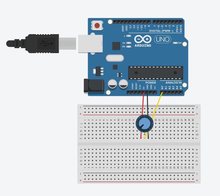
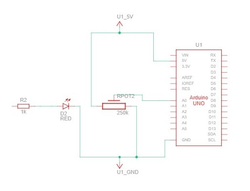
This week’s assignment drew inspiration from a familiar scenario: those late-night kitchen escapades for sneaky snacks. At home, the kitchen lights, being downlighters, don’t just instantly switch on. Instead, there’s a gradual shift when we turn the knob. This unique characteristic prompted me to recreate this experience in my circuit. The analog representation was brought to life through the potentiometer, mirroring the gradual adjustment of the kitchen lights, while the digital side found expression in the toggle switch.
To bring my circuit to life, I gathered a few key components: a potentiometer, a toggle switch, jumper cables, two 10k ohm resistors, one 330-ohm resistor, and two LEDs. The interplay of these elements resulted in the creation of a circuit, visually captured in the image below.
In the process of setting up the circuit, I encountered challenges associated with ensuring the correct placement of components, whether they operated in the digital or analog realm. Despite these hurdles, I noticed a significant improvement in my ability to assemble the circuit compared to my initial attempts. This project underscored the importance of understanding the specific pins corresponding to digital and analog features on the Arduino Uno board. Aligning the code with the appropriate pin modes became crucial for a seamless execution.
Here’s a snippet of the code that brought my project to life:
void loop() {
  int sensorValue= analogRead(A1);
  int buttonState = digitalRead(A2);
  Serial.println(sensorValue);


 analogWrite(led, sensorValue/4);

 delay(30);

 if (buttonState == LOW) {

digitalWrite(13, LOW);

} else {

digitalWrite(13, HIGH);

}
}
Below is the video representation of my assignment.
Reflecting on the project, I recognize its conceptual completeness, yet I aspire to enhance its creative aspect. While the current iteration captures the assignment’s essence, I envision experimenting with diverse LED blinking patterns, moving beyond the conventional blink. Additionally, exploring the possibility of using the potentiometer to control multiple LEDs could add a layer of complexity and creativity to the project, elevating it beyond its current simplicity.
This week’s reading from Tigoe was all about Physical Computing and interactive media art, and it was super enlightening. One part that really caught my attention was the reading on Making Interactive Art. It talked about three key things to keep in mind when creating interactive artwork: setting the stage, shutting up, and listening.
The idea that your artwork should speak for itself really stuck with me. Many times, we create art and start questioning ourselves – is it good enough? How do I explain my thoughts behind it? This reading basically said, you don’t have to explain anything. Your artwork can stand on its own.
This got me thinking about the interactive showcase we saw at the beginning of the semester. We were given the freedom to explore, touch, sit, stand, and feel. It was about being alone together. The artist didn’t have to explain anything; the experience spoke for itself. It made me aspire to create art that lets people think what they want.
Connecting this to another reading, Physical Computing hits and misses, I realized that the sense of freedom in interactive art extends to the technical side too. Even if something similar has been done before, you have the liberty to make changes and adjustments. Set the stage, make it your own, and then, shut up and listen. This means letting your work be interpreted by others who might have seen something similar but are experiencing a different variation through your lens.
These readings teach us crucial lessons for dealing with interactive art. Don’t let external opinions affect your work. Do what you need to do and let the art speak for itself. It’s about giving your audience the freedom to perceive and connect with your work on their terms.