Final Project: Human Following Robot

Concept

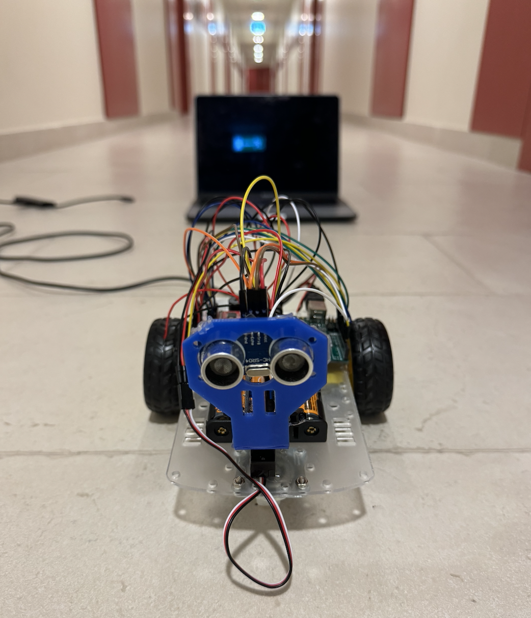
For my final project, I decided to create a human-following robot that I like to think of as a non-human pet, inspired by none other than Wall-E – that lovable robot from the movies. Just like Wall-E, my creation is meant to tag along beside you, sensing your presence and movement with its built-in sensors. It’s a robot that follows you around, imitating the way a curious pet might trail after its owner.

But there’s a twist – it’s not just an automatic follower. With P5JS, a programming tool, you get the reins, too. You can control it like you’re playing a video game, guiding it around with your keyboard and mouse. The idea struck me while watching Wall-E’s adventures, and I thought, why not blend that inspiration into something real? Something you can interact with, just like a pet that’s eager for your attention, whether it’s autonomously roaming or being directed by your commands.

Hardware Image

User Testing Videos

Key Components

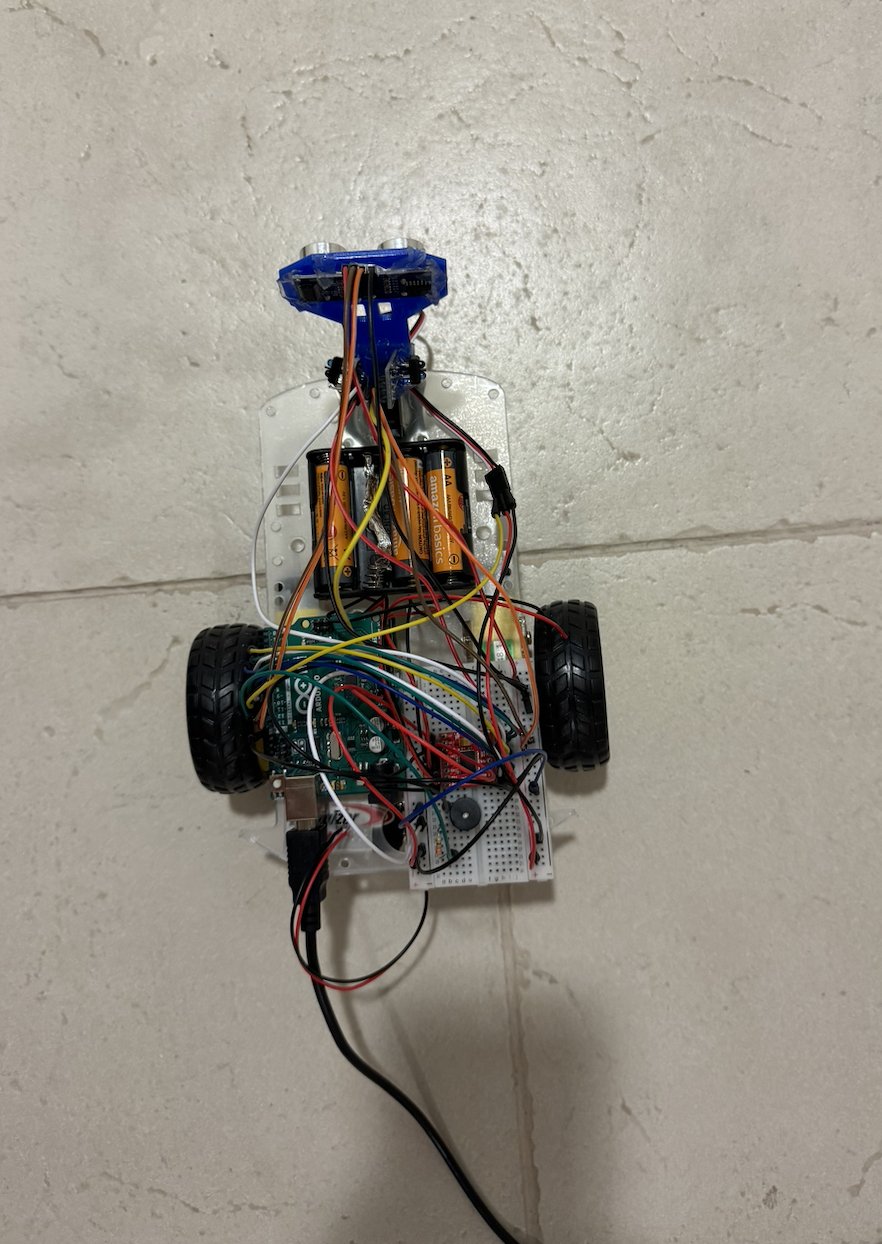
  • Arduino Uno: The Arduino Uno acts as the brain of our robot. It’s a microcontroller responsible for processing data from sensors, making decisions, and controlling the motors and servo. The best part? It’s beginner-friendly, making it an ideal choice for those new to robotics.
  • Motor Driver: the powerhouse behind the robot’s movement. It precisely controls the motors that drive the wheels, ensuring our robot gracefully follows its human companion.
  • Ultrasonic Sensor: The ultrasonic sensor serves as the robot’s eyes, allowing it to measure distances. This is crucial for avoiding collisions and maintaining a safe following distance.
  • IR Sensor: Our robot needs to be smart enough to navigate around obstacles. That’s where the IR sensor comes in, allowing the robot to turn. By emitting and detecting infrared radiation, it enhances obstacle detection.
  • Servo Motor: It helps move the ultrasonic sensor, giving the robot flexibility.
  • Motors and Wheels: For our robot to follow, it needs reliable motors and wheels. The motor driver ensures these components work seamlessly, making our robot mobile and ready for adventure.
  • Piezo Speaker: Communication is key, even for robots. The piezo speaker provides audible feedback, alerting users that robots is ready to operate.

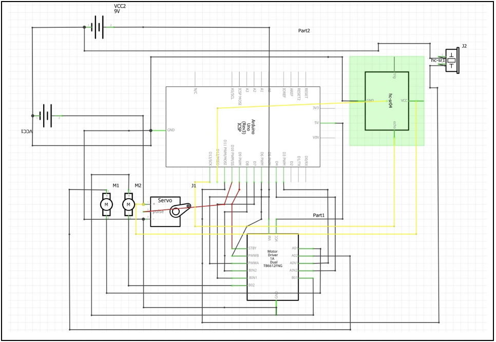
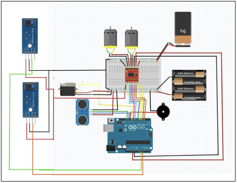
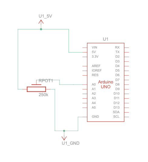
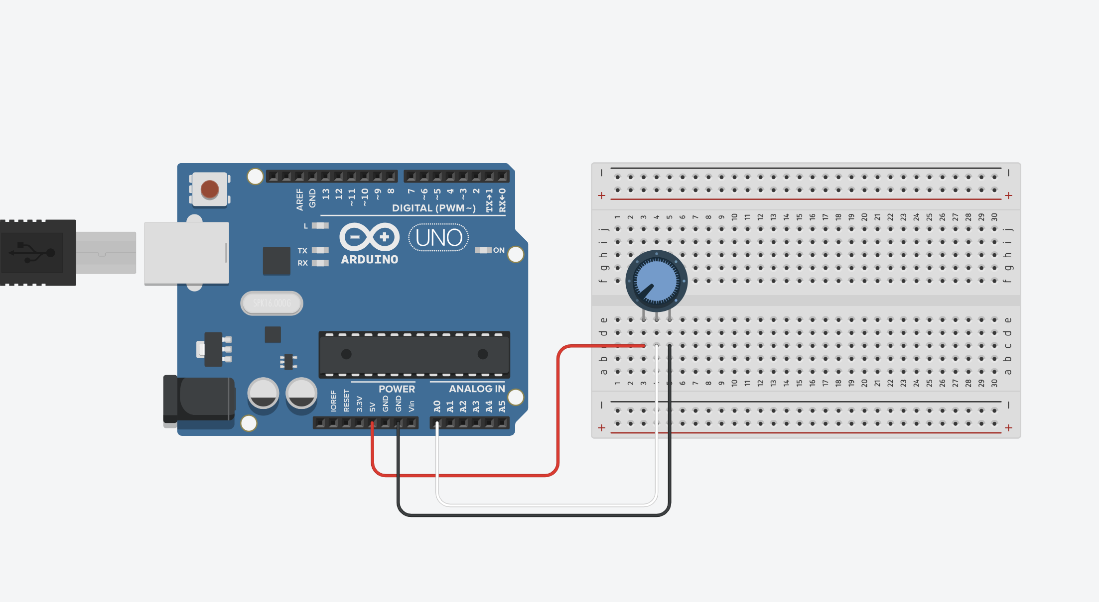
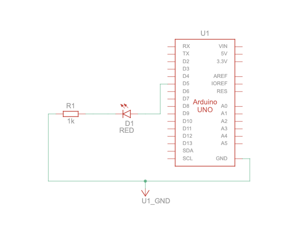
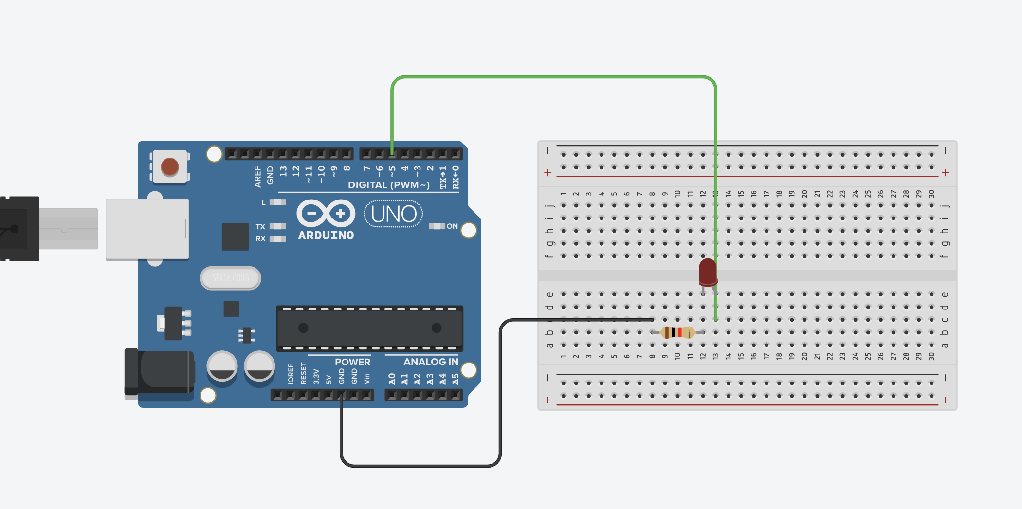
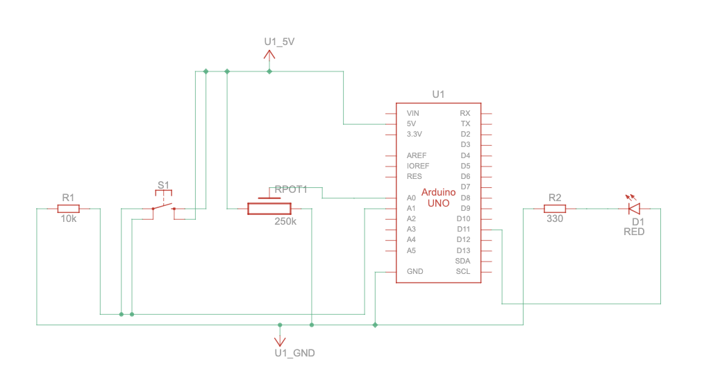
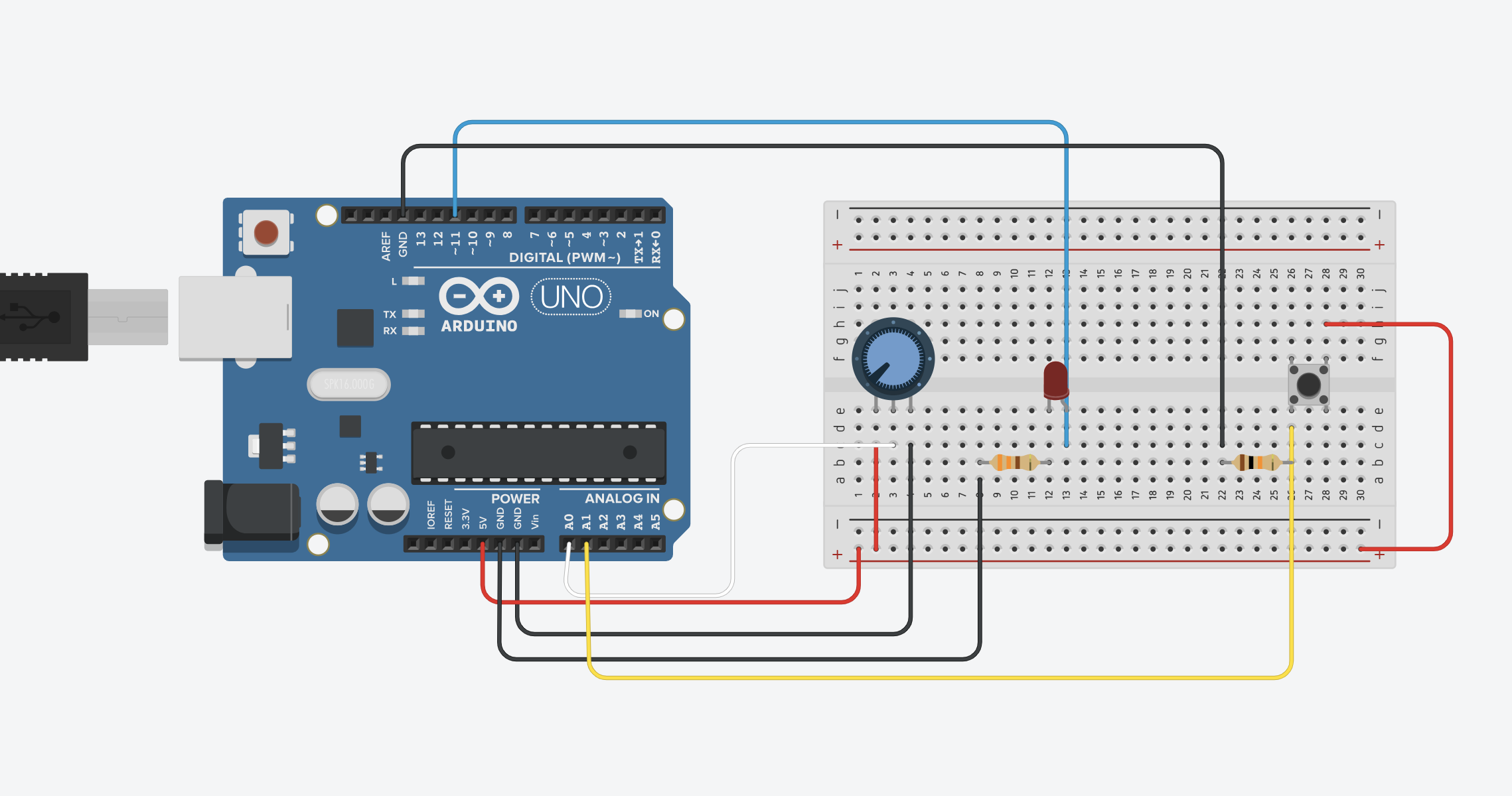
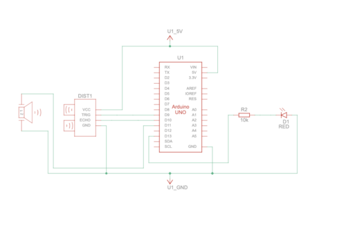
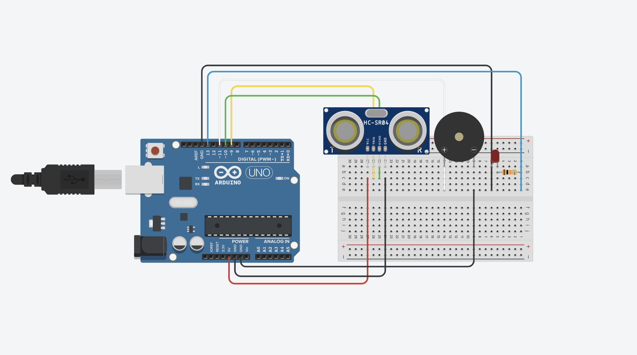
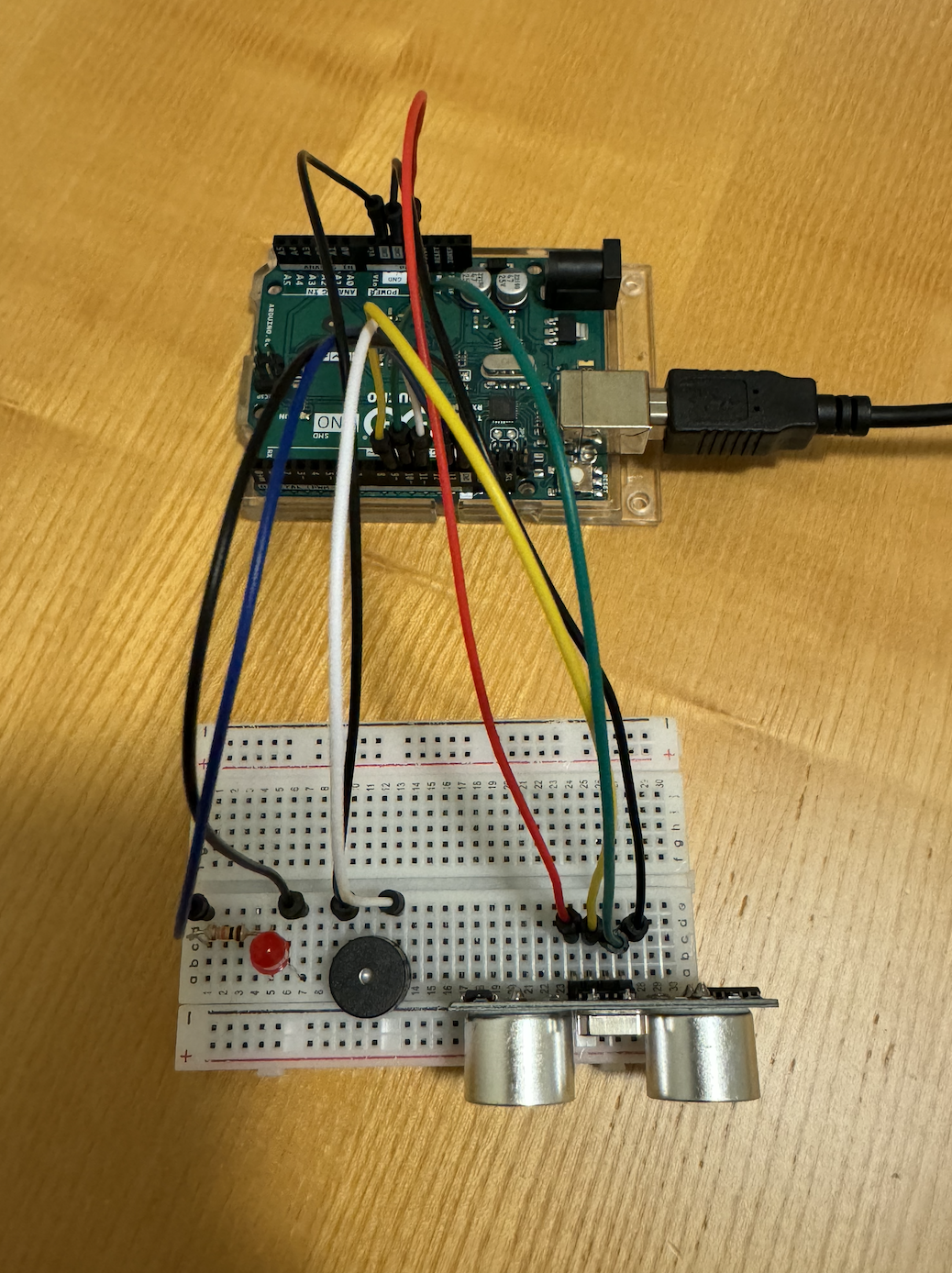
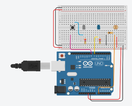
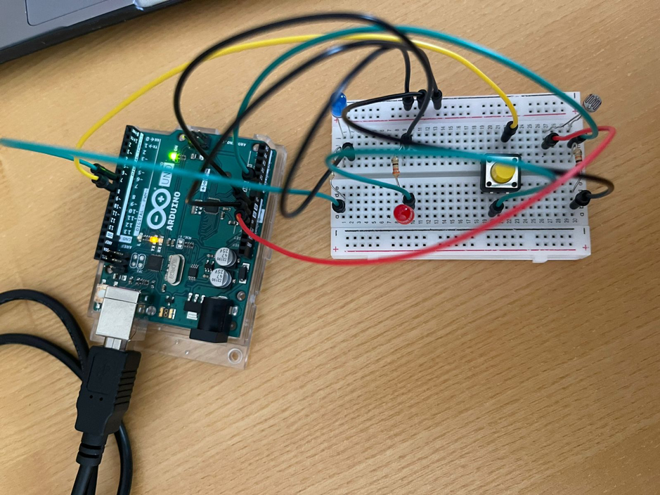
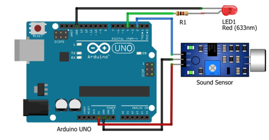
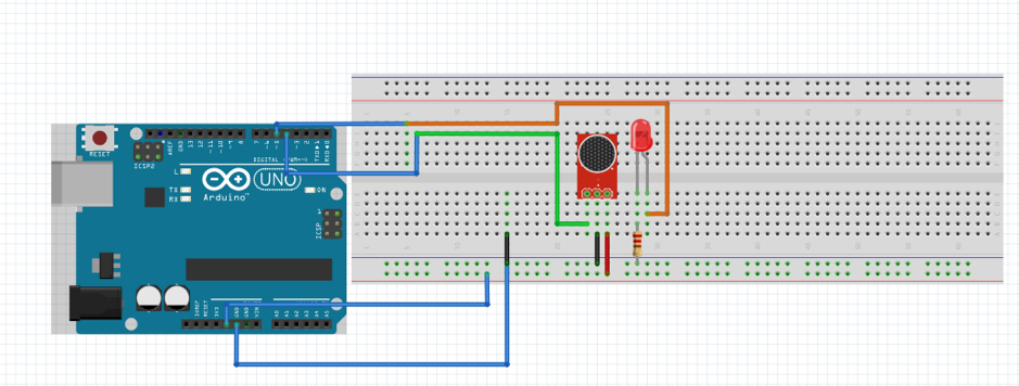
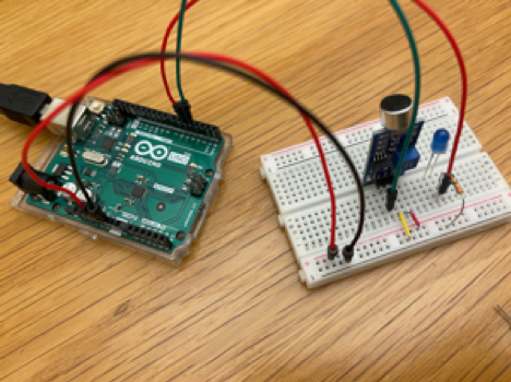
Schematic and Circuit Diagram

Implementation details

  • Interaction Design: The interaction design of my project centers on a user-friendly and intuitive experience. The robot operates in two modes: autonomous, where it uses sensors to follow the user around, and manual, where the user can control its movements through a P5JS interface. Switching between modes is seamless, catering to moments when you want a companionable presence without the effort or times when you prefer direct control.
  • Arduino Description: The Arduino code for my project serves as the brain of my pet-like robot. It integrates motor control with sensor inputs to enable the robot to follow a person autonomously or be controlled manually via P5JS. The code dictates how the robot moves in response to what the sensors detect, like proximity to objects or a person’s movements. It manages the logic for when the robot should move forward, turn, or stop to ensure smooth operation. Additionally, the code includes functions for playing melodies and controlling servo movements, giving the robot a lively and interactive character.

Code Snippet:

#include <SparkFun_TB6612.h>
#include "pitches.h"
#include <Servo.h>
//Motor Driver Pins
#define AIN1 3
#define BIN1 7
#define AIN2 4
#define BIN2 8
#define PWMA 5
#define PWMB 6
#define STBY 9

// Motor speed and control variables
const int offsetA = 1;
const int offsetB = 1;
int speed = 100;
int brightness = 0; // Variable to receive serial data for control

// Initialize motor objects with defined pins and offsets
Motor motor1 = Motor(AIN1, AIN2, PWMA, offsetA, STBY);
Motor motor2 = Motor(BIN1, BIN2, PWMB, offsetB, STBY);


//Ultrasonic Sensor
int distance;
long timetaken;
double feet, inch;

// Define ultrasonic sensor pins
#define echoPin 13
#define trigPin 12

// Define IR sensor pins
#define IRR A0  //pin for right sensor
#define IRL A1  //pin for left sensor


//Define Buzzzer pins
int speaker = 11;
int melody[] = {
  NOTE_C4, NOTE_G3, NOTE_G3, NOTE_A3, NOTE_G3, 0, NOTE_B3, NOTE_C4
};

// Melody and note durations arrays for the buzzer
int noteDurations[] = {
  4, 8, 8, 4, 4, 4, 4, 4
};

//Servo Motor initialization
Servo myservo;
int pos = 0; // Variable to store the servo position

void setup() {
    // Setup for ultrasonic sensor
  pinMode(trigPin, OUTPUT);  //ultrasonic sensor
  pinMode(echoPin, INPUT);

  // Setup for IR sensors
  pinMode(IRL, INPUT);  //left ir sensor
  pinMode(IRR, INPUT);  //right ir sensor

  //plays instrumental tones
  for (int thisNote = 0; thisNote < 8; thisNote++) {

    // to calculate the note duration, take one second divided by the note type.
    //e.g. quarter note = 1000 / 4, eighth note = 1000/8, etc.
    int noteDuration = 1000 / noteDurations[thisNote];
    tone(11, melody[thisNote], noteDuration);

    int pauseBetweenNotes = noteDuration * 1.30;
    delay(pauseBetweenNotes);
    // stop the tone playing:
    noTone(11); 
  }

  // Setup for servo motor
  myservo.attach(10);
  for (pos = 0; pos <= 180; pos += 1) {  // goes from 0 degrees to 180 degrees
    // in steps of 1 degree
    myservo.write(pos);  // tell servo to go to position in variable 'pos'
    delay(15);           // waits 15ms for the servo to reach the position
  }
  for (pos = 180; pos >= 0; pos -= 1) {  // goes from 180 degrees to 0 degrees
    myservo.write(pos);                  // tell servo to go to position in variable 'pos'
    delay(15);                           // waits 15ms for the servo to reach the position
  }
  pinMode(A3, OUTPUT);

  // Initialize Serial communication
  Serial.begin(9600);
}

void loop() {
    // Main loop for sensor reading and motor control
  int distance, readLeft, readRight;

  // Read ultrasonic sensor distance
  distance = ultra();
  Serial.println(distance);

    // Read IR sensor states
  readRight = digitalRead(IRR);
  readLeft = digitalRead(IRL);

  // Movement and control logic based on sensor readings
  if (readLeft == 1 && distance > 10 && distance < 25 && readRight == 1) {
    forward(motor1, motor2, speed); // Move forward
  } else if (readLeft == 1 && readRight == 0) {  //turn right
    left(motor1, motor2, speed);
  } else if (readLeft == 0 && readRight == 1) {  //turn left
    right(motor1, motor2, speed);
  } else if (readLeft == 1 && readRight == 1) {
    brake(motor1, motor2); // Brake the motors
  } else if (distance > 5 && distance < 10) {
    brake(motor1, motor2); // Brake if within a specific distance range
  } else if (distance < 5) {
    back(motor1, motor2, speed); // Move backward
  }

  // Remote control logic via Serial communication
  if (Serial.available() > 0) { // Check if there is any Serial data available
    // read the most recent byte (which will be from 0 to 255):
    brightness = Serial.read();

        // Conditional statements to control the robot based on the received byte
    if (brightness == 0) {
       // If the received byte is 0, move the robot forward
        // The function 'forward' is called with motors and speed as arguments
      forward(motor1, motor2, 200);
    } else if (brightness == 1) {
       // If the received byte is 1, move the robot backward
        // The function 'back' is called with motors and speed as arguments
      back(motor1, motor2, 200);
    }
  }
}


  •  Description of P5: In the P5.js code, there’s a dual-feature interface for my robot. It visually represents the sensor data, showing a value that decreases as you get closer to the robot and increases as you move away, mirroring the robot’s perception in real-time. Simultaneously, this interface allows you to control the robot’s movement. With simple commands, you can guide the robot to move forward or backward, offering a straightforward and interactive way to both visualize and manipulate the robot’s position and actions.

Code Snippet:

let serial; // variable for the serial object
let latestData = "wait"; // variable to hold the
let val = 0; // Variable to store a value for serial communication
let colorValue = 0;

function setup() {
  createCanvas(1000, 800);
  textSize(18);
  // serial constructor
  serial = new p5.SerialPort();

  // serial port to use - you'll need to change this
  serial.open("/dev/tty.usbmodem141101");

  // what to do when we get serial data
  serial.on("data", gotData);
}

// Callback function for processing received serial data
function gotData() {
  let currentString = serial.readLine(); // Read the incoming data as a string
  trim(currentString); // Remove any leading/trailing whitespace
  if (!currentString) return; // If the string is empty, do nothing
  console.log(currentString); // Log the data to the console for debugging
  latestData = currentString; // Update the latestData variable
}

function draw() {
  background(211, 215, 255);
  fill(102, 11, 229);

  // Map the latestData to a rotational degree value
  let rotDeg = map(latestData, 0, 1000, 0, 10000);

  // Check for the space bar key press to start
  if (key != " ") {
    // Display the starting screen
    textSize(30);
    fill(0, 0, 0);
    rect(0, 0, 1000, 800); // Draw a black rectangle covering the canvas
    fill(200, 200, 200); // Set text color
    text("PRESS SPACE BAR TO START THE HFR", width / 4, height / 2);
  } else {
    // Main interaction screen
    // Display forward and backward areas and instructions
    textSize(18);

    // Forward area
    fill(102, 11, 229);
    rect(890, 0, 110, 1000); // Draw the forward area
    fill(255, 245, 224);
    text("FORWARD", 900, 450); // Label for the forward area

        // Backward area
    fill(102, 11, 229);
    rect(0, 0, 110, 1000); // Draw the backward area
    fill(255, 255, 255);
    text("BACKWARD", 0, 450); // Label for the backward area

        // Draw the robot representation
    fill(35, 45, 63);
    rect(500, -100, 100, 600);  // Draw the robot's body
    fill(180, 101, 229);
    rect(500, 500, 100, -rotDeg); // Draw the robot's moving part

        // Additional robot features
    fill(200, 120, 157);
    rect(500, 500, 100, 80); // Base of the moving part
    fill(0, 0, 0);
    rect(460, 580, 40, -30); // Left wheel
    rect(600, 580, 40, -30); // Right wheel
    fill(255, 255, 255);
    text(latestData, 540, 560); // Display the latest data
    
        // Display control instructions
    fill("black");
    text("Control the Robot:\n\n", 470, 600);
    text(
      "Forward Movement:\n" +
        "- 'Forward' area on right\n" +
        "- Click to move forward\n" +
        "- Click again to stop\n\n",
      670,
      650
    );
    text(
      "Backward Movement:\n" +
        "- 'Backward' area on left\n" +
        "- Click to move backward\n" +
        "- Click again to stop\n\n",
      150,
      650
    );
    text("Move mouse to desired side and click to control movement!", 300, 770);
    textStyle(BOLD);


        // Serial communication based on mouse position
    if (!colorValue) {
      if (mouseX <= width / 2) {
        val = 1; // Set val to 1 if mouse is on the left half
        serial.write(val); // Send val to the serial port
        console.log("Left"); // Log the action
      } else {
        val = 0; // Set val to 0 if mouse is on the right half
        serial.write(val); // Send val to the serial port
        console.log("Right"); // Log the action
      }
    }
  }
    // Draw a circle at the mouse position
  fill(255, 255, 255);
  ellipse(mouseX, mouseY, 10, 10);
}
// Function to handle mouse click events
function mouseClicked() {
  if (colorValue === 0) {
    colorValue = 255;
  } else {
    colorValue = 0;
  }
}

  • Communication between Arduino and p5.js:

In this project, the Arduino sends sensor data to P5.js, allowing for a visual representation of proximity; the closer you are to the sensor, the lower the number, and vice versa. P5.js then sends back control commands to Arduino, enabling the user to maneuver the robot forward and backward. This bidirectional communication between Arduino and P5.js is streamlined through serial communication, using an application called SerialControl to effectively connect ports in P5.js. This setup ensures efficient data transfer and responsive control of the robot’s movements.

Something I am Proud of

I’m particularly proud of the hardware implementation aspect of my robot project. It was a journey that demanded considerable time, effort, and a variety of materials to reach the final outcome. The process of assembling and fine-tuning the hardware, from selecting the right sensors and motors to designing and building the physical structure, was both challenging and rewarding. Seeing the components come together into a functioning robot was a testament to the hard work and dedication put into this project. This aspect of the project stands out for me as a significant achievement.

Challenges Faced

One of the challenges I faced was with the P5.js control interface. When trying to remotely control the robot, it moved extremely slowly, and at times, it would completely stop responding, even though I was actively trying to move it. I spent a significant amount of time troubleshooting this issue, delving into various aspects of the code and communication protocols. Eventually, I came to realize that this might be a limitation within the system, possibly related to lag or processing delays, which seem to occur quite frequently.

Another challenge I encountered involved the power supply for the robot. Initially, I had a battery pack with four cells, totaling 6V, but my robot only required 4.5V. To adjust the voltage, I removed one cell and connected a wire to bridge the gap. However, this setup proved problematic; as the robot moved, the wire would shift its position, causing intermittent power loss and loss of control. The robot would continue moving uncontrollably until I reconnected the wire. To resolve this, I came up with a creative solution. I crafted a connector using aluminum foil, shaping it to fit securely on both ends of the battery compartment. This improvised connector ensured a stable connection, eliminating the issue of the wire shifting during movement. With this fix, the robot now operates smoothly without any control issues.

Future Improvements

In terms of future improvements for my project, one key area I’d like to focus on is enhancing the P5.js sketch to make it more interactive and engaging. I plan to introduce multiple pages within the sketch, each offering different functionalities or information, to create a more comprehensive and user-friendly interface. Additionally, I’m considering integrating sound into the P5.js environment. This could include audio feedback for certain actions or ambient sounds to make the interaction with the robot more immersive and enjoyable. These improvements aim to not only enrich the user experience but also add layers of complexity and sophistication to the project.

IM Show!

It was an honor to showcase my human-following robot at the IM show. Seeing the enthusiasm and curiosity of students and faculty members as they passed by to test my robot was a heartwarming experience. I was particularly thrilled to witness the interest of professors who have been integral to my learning journey. Among them was Evi Mansor, who taught me in the communications lab; her impressed reaction was a significant moment for me. Additionally, Professor Michael Shiloh, a well-known figure in the IM department, showed keen interest in my project. A special and heartfelt thanks goes to Professor Aya Riad, whose guidance and teaching were pivotal in developing the skills necessary to create such an innovative and successful outcome. The support and the lively interest of the audience made the event a memorable highlight of my academic journey.

Resources

  • https://youtu.be/yAV5aZ0unag?si=ZzwIOrRLBYmrv34C
  • https://youtu.be/F02hrB09yg0?si=d40SgnSfkBMgduA8
  • https://youtu.be/suLQpNPLzDo?si=G2rJR6YrsynycGoK
  • https://circuitdigest.com/microcontroller-projects/human-following-robot-using-arduino-and-ultrasonic-sensor
  • https://projecthub.arduino.cc/mohammadsohail0008/human-following-bot-f139db


Final Project Draft 2: HFR

Concept
In my previous blog post, I introduced the idea of creating a Human Following Robot inspired by sci-fi movies like Wall-E. The concept revolves around developing a robot companion that autonomously follows a person, adjusting its position based on their movements. This project aims to bring a touch of cinematic magic into real life by utilizing sensors as the robot’s eyes and ears, allowing it to perceive the presence and actions of the person it follows.

Key Components
1. Ultrasonic Sensor:
Role: Measures the distance between the robot and a person.
Functionality: Enables the robot to make decisions about its movement based on the person’s proximity.
2. DC Motors and Motor Driver:
Role: Facilitates the robot’s movement.
Functionality: Allows the robot to move forward, backward, and turn, responding to the person’s position.
3. Servo Motor:
Role: Controls the direction in which the robot is facing.
Functionality: Adjusts its angle based on the horizontal position of the person, ensuring the robot follows the person accurately.
4. P5.js Integration:
Role: Provides visualization and user interface interaction.
Functionality: Creates a graphical representation of the robot’s perspective and the person’s position. Visualizes the direction of the servo motor, offering a clear indicator of the robot’s orientation.

Finalized Concept
Building upon the initial concept, the finalized idea is to implement a real-time human following mechanism. The robot will utilize the input from the ultrasonic sensor to determine the person’s distance, adjusting its movement accordingly. The servo motor will play a crucial role in ensuring the robot faces the person, enhancing the user experience.

Arduino Program
Inputs: Ultrasonic sensor readings for distance measurement.
Outputs: Control signals for DC motors based on a person’s proximity.

Video 1

P5 Program
The P5 program will focus on creating a visual representation of the robot’s perspective and the person’s position. It will receive data from the Arduino regarding the robot’s orientation and the person’s horizontal position, updating the graphical interface accordingly. (I’m thinking of representing an ellipse where the closer you are to the sensor the smaller the ellipse and the further you are the larger it gets). Furthermore, I have tried to implement a clickable control in p5 where it can move the robot frontwards and backwards by clicking on the right and left side of the p5 sketch.

Video 2 


Project Proposal Idea

Concept

For my project, I’m working on a Human Following Robot – you know, something straight out of a sci-fi movie, and Wall-E definitely comes to mind. The whole idea is to create this robot buddy that can autonomously follow people around, kind of like a helpful sidekick. It hit me after watching Wall-E, and I thought, why not bring a touch of that magic into real life?

So, here’s the plan: I’ll be using sensors to catch someone’s presence and their moves. Think about it like a buddy who always walks by your side, adjusting its position as you go. No need for a remote or anything – it just picks up on your vibe and tags along. The key components here are these cool sensors – they’re like the robot’s eyes and ears, helping it figure out where you are and what you’re up to.

Week 11 – Reflection Assignment

The writer of Design Meets Disability delves into using design to make the needs of disabled people more fashionable. However, they fail to take into account that not every disabled person wants to make their disability their entire personality. While some of the designs he showed were stunning, they may be too “out there” for someone who doesn’t want to make a big deal of their disability. I know a couple of disabled people who would actually be uncomfortable with the idea that their disability would be used as a fashion statement. That being said, there is nothing wrong with making it a fashion statement for those who willingly choose to do so. I would also like to point out that the writer made it seem that the “normal” products for disabled people were not good enough. In reality, most people can’t afford to get designer prosthetics or hearing aids. They should not be made to feel like they’re getting the short end of the stick.

I particularly liked how the writer mentioned how hearing aid companies are trying to make their products more invisible by making them smaller and hidden. On the other hand, eyeglass companies are trying to make their products more out there to show off as a fashion statement. I never noticed this contrast before but it was quite interesting to realize. I think that perhaps because glasses are more commonly worn than hearing aids that they’re more widely accepted and people are more comfortable with wearing them publicly instead of keeping them hidden like hearing aids. Furthermore, the writer also delves into modern technologies that value simplicity and accessibility. I found this to be very different compared to his original view where he wanted disability products to be less simple and more fashion-forward. As someone who is into fashion, I would want nothing more than to make a statement unless it comes in the way of my comfort and accessibility. While some of the designs he showed were gorgeous, some like the hand prosthetic looked less functional and more just a fashion statement.

In Class Exercises

Exercise 1: ARDUINO TO P5 COMMUNICATION

Schematic

Circuit Diagram 

P5.js Code
We used the same example provided in class, however, we just added this part to the code:

function draw() {
  
  background('#6FA9B0')

  if (!serialActive) {
    fill("rgb(255,255,255)")
    text("Press Space Bar to select Serial Port", 20, 30);
  } else {

    noStroke()
    // draw a circle, alpha value controls the x-position of the circle
    circle(map(alpha, 0, 1023, 0, 640), 240, 50)

  }
}

Arduino

We used the same one provided in class.

Video

Exercise 2: P5 TO ARDUINO COMMUNICATION

Schematic

Circuit Diagram 

P5.js Code

let brightness = 0; 
let slider;
let img;

//preload images
function preload(){
  img = loadImage('sun.png');
  img2 = loadImage('moon.png');
}

function setup() {
  createCanvas(400, 400);
  //create slider
  slider = createSlider(0, 255, 100);
  slider.position(width/2-50,height/2+25);
  slider.style('width', '80px');
}

function draw() {
  background('#85CCEC');
  image(img,235,130,150,180); 
  image(img2,30,140,100,160);
  
  let val = slider.value();
  brightness = val;
  
  // instructions
  textAlign(CENTER,CENTER);
  textSize(16);
  textStyle(BOLD)
  text("Control the brightness using the slider below!",width/2,100);
  
  //connects serial port
  if (!serialActive) {
    textSize(10);
    text("Press Space Bar to select Serial Port", 100, 30);
  } else {
    textSize(10);
    text("Connected",100,30);
  }


}

function keyPressed() {
  if (key == " ") {
    // important to have in order to start the serial connection!!
    setUpSerial();
  }
}


function readSerial(data) {

  //READ FROM ARDUINO HERE
  
  if (data != null) {
    // if there is a message from Arduino, continue
    
    //SEND TO ARDUINO HERE (handshake)
    
    let sendToArduino = brightness + "\n";
    writeSerial(sendToArduino);
  }
}

Arduino Code

int LED = 5;
void setup() {
  Serial.begin(9600);
  pinMode(LED, OUTPUT);
  // start the handshake
  while (Serial.available() <= 0) {
    Serial.println("Wait");  // send a starting message
    delay(300);               // wait 1/3 second
  }
}
void loop() {
  // wait for data from p5 before doing something
  while (Serial.available()) {
    int brightness = Serial.parseInt(); 
    if (Serial.read() == '\n') {
      analogWrite(LED, brightness); // turn on LED and adjusts brightness
      Serial.println("LIT"); 
    }
  }
}

Video

Exercise 3: BI-DIRECTIONAL COMMUNICATION

Schematic

Circuit Diagram 

P5.js Code

let hit = 0;  // whether the ball hit the ground
let reset = 0;  // whether Arduino sent a reset argument (a button press)

// Ball physics
let velocity;
let gravity;
let position;
let acceleration;
let wind; // wind direction is controlled by Arduino (potentiometer)
let drag = 0.99;
let mass = 50;

function setup() {
  createCanvas(600, 600);
  noFill();
  position = createVector(width / 2, 0);
  velocity = createVector(0, 0);
  acceleration = createVector(0, 0);
  gravity = createVector(0, 0.5 * mass);
  wind = createVector(0, 0);
}

function draw() {
  background('pink');
  applyForce(wind);
  applyForce(gravity);
  velocity.add(acceleration);
  velocity.mult(drag);
  position.add(velocity);
  acceleration.mult(0);
  fill(255)
  ellipse(position.x, position.y, mass, mass);
  if (position.y > height - mass / 2) {
    velocity.y *= -0.9; // A little dampening when hitting the bottom
    position.y = height - mass / 2;
    hit = 1;
  } else {
    hit = 0;
  }

  if (!serialActive) {
    console.log("Press Space Bar to select Serial Port");
  } else {
    // 
    // console.log("Connected");
    if (reset == 1) { // if reset signal is sent and flagged (button press)
      reset = 0; // clear the flag
      
      // reset ball with some random mass
      mass = random(15, 80);
      position.x = width / 2;
      position.y = -mass;
      velocity.mult(0);
    }
  }
}

function applyForce(force) {
  // Newton's 2nd law: F = M * A
  // or A = F / M
  let f = p5.Vector.div(force, mass);
  acceleration.add(f);
}

function keyPressed() {
  if (key == " ") {
    // important to start the serial connection!
    setUpSerial();
  }
}

function readSerial(data) {
  
  //READ FROM ARDUINO HERE
  

  if (data != null) {
    // split the message
    let fromArduino = split(trim(data), ",");
    // if the right length, then proceed
    if (fromArduino.length == 2) {
      reset = fromArduino[0];
      wind.x = fromArduino[1];
    }

    
    //SEND TO ARDUINO HERE (handshake)
    
    let sendToArduino = hit + "\n";
    writeSerial(sendToArduino);
  }
}

Arduino Code

int buttonSwitch = A2;
int potentiometer = A0;
int ledOut = 11;

void setup() {
  Serial.begin(9600);
  pinMode(12, OUTPUT);
  digitalWrite(ledOut, LOW);  // in the case of reconnection while p5 is running
  // start the handshake
  while (Serial.available() <= 0) {
    Serial.println("-1,-1");  // send a starting message
    delay(300);               // wait 1/3 second
  }
}

void loop() {
  // wait for data from p5 before doing something
  while (Serial.available()) {
    int hit = Serial.parseInt(); // receives 1 argument, whether the ball hit the ground
    if (Serial.read() == '\n') {
      digitalWrite(ledOut, hit); // turn on LED if the ball is in contact with the ground (1 -> HIGH) turn off LED if not (0, -> LOW)
      int sensor = digitalRead(buttonSwitch); // read button
      delay(1);
      int sensor2 = analogRead(potentiometer); // read potentiometer
      delay(1);
      Serial.print(sensor); // button
      Serial.print(',');
      if (sensor2 < 512) { // potentiometer; depending whether the value is over or below half, direction of the wind is set
        Serial.println(1);
      } else {
        Serial.println(-1);
      }
    }
  }
}

Video

EchoGuard: Your Personal Parking Assistant

Concept

Our assigment idea was sparked by a common scenario we all encounter – parking a car in reverse. In discussing the challenges of accurately judging the distance, my partner and I realized the potential hazards and the lack of a reliable solution. Considering how much we rely on the beeping sensor in our own cars for safe parking, we envisioned a solution to bring this convenience to everyone. Imagine a situation where you can’t live without that reassuring beep when you’re reversing. That’s precisely the inspiration behind our assigment – a beeping sensor and a light that mimics the safety we’ve come to depend on, implemented with a car toy to illustrate its practical application.

Required Hardware

– Arduino
– Breadboard
– Ultrasonic distance sensor
– Red LED
– 10k resistor
– Piezo speaker
– Jumper wires

Schematic Diagram

Circuit Diagram

Setting Up the Components

Ultrasonic Distance Sensor Connections:
VCC to 5V
TRIG to digital pin 9
ECHO to digital pin 10
GND to GND on the Arduino

Speaker Connections:
Positive side to digital pin 11
Negative side to GND

LED Connections:
Cathode to GND
Anode to digital pin 13 via a 10k resistor

Coding the Logic

// defines pins numbers
const int trigPin = 9;
const int echoPin = 10;
const int buzzerPin = 11;
const int ledPin = 13;

// defines variables
long duration;
int distance;
int safetyDistance;

// Define pitches for the musical notes
int melody[] = {262, 294, 330, 349, 392, 440, 494, 523}; 

void setup() {
  pinMode(trigPin, OUTPUT); // Sets the trigPin as an Output
  pinMode(echoPin, INPUT);  // Sets the echoPin as an Input
  pinMode(buzzerPin, OUTPUT);
  pinMode(ledPin, OUTPUT);
  Serial.begin(9600); // Starts the serial communication
}

void loop() {
  // Clears the trigPin
  digitalWrite(trigPin, LOW);
  delayMicroseconds(2);

  // Sets the trigPin on HIGH state for 10 microseconds
  digitalWrite(trigPin, HIGH);
  delayMicroseconds(10);
  digitalWrite(trigPin, LOW);

  // Reads the echoPin, returns the sound wave travel time in microseconds
  duration = pulseIn(echoPin, HIGH);

  // Calculating the distance
  distance = duration * 0.034 / 2;

  safetyDistance = distance;
  if (safetyDistance <= 5) {
    // Play a musical note based on distance
    int index = map(safetyDistance, 0, 5, 0, 7); // Map distance to array index
    tone(buzzerPin, melody[index]); // Play the note
    digitalWrite(ledPin, HIGH);
  } else {
    noTone(buzzerPin); // Stop the tone when not close
    digitalWrite(ledPin, LOW);
  }

  // Prints the distance on the Serial Monitor
  Serial.print("Distance: ");
  Serial.println(distance);
}


Hardware Implementation

Video Illustration (Initial idea with beeping sound)

Video Illustration 2 (using melody)

Working Explanation and Conclusion
The ultrasonic distance sensor measures the gap between the car and the sensor on the breadboard. When the distance diminishes below a predefined threshold (5 units in our design), the buzzer emits a warning sound, and the red LED illuminates, acting as a clear visual cue for the driver to halt. This Arduino-based system seamlessly combines hardware and software, offering an elegant solution to a common problem. In creating this assignment, we’ve not only simplified the process of reverse parking but also contributed to enhancing overall safety, turning our initial conversation into a tangible, practical innovation.

Week 10 – Reflection Assignment

The first reading, “A Brief Rant on the Future of Interaction Design,” delves into the future of technology and how Bret Victor has a problem with it. Victor reveals how the future they are portraying consists of swiping through a touchscreen for every task. He believes that this limits the use of our hands as we aren’t doing anything with them other than swiping. Victor wants to see a future where we can grab, throw, hold, and feel technology rather than just swiping through a screen. Reflecting back on this reading, I completely disagree with Victor’s narrative. The whole point of technology innovation is to make things more accessible and user-friendly. It is supposed to make tasks easier to do and faster as well. If all we’re doing with our hands is swiping, is that really a bad thing? Victor’s issue is that we’re not using our hands enough. In reality, we’re using our hands to do a lot of other things like cooking, laundry, making our bed, etc. So if we’re using our hands to do all these things, is it really bad that the innovation of technology means all we’re doing with just technology is swiping? Moreover, Victor also fails to take into account that technology, where we don’t require using much of our body, is beneficial to several people of determination who may have a hard time interacting with limited mobility or cognitive function.

The second reading, “Responses: A Brief Rant on the Future of Interaction Design,” is a response posted by Brent Victor where he responds to the questions he received after posting the initial rant. However, his responses to most of the questions don’t even look like responses but rather an angry teenager responding to hate comments. By mentioning that he is no longer going to respond to any more questions, it is as though he has turned off the comments on his Instagram post due to fear of being shamed by the public. One question someone asked was about using voice for more interactive technology. Victor responded by saying that we should just use our voice for asking questions and issuing commands. With that logic, one could respond by stating that why don’t we just use our hands as well for doing tasks like cooking, laundry, etc.? Why do we need to use more of them for interactive technology? The whole rant by Victor made no sense and it is not a surprise that he no longer works in making such technology.

The main connecting factor between both these readings is that it was written by Brent Victor, who only thinks that he is right and everyone else is wrong. In both these readings, Victor wants the future of technology to be less user-friendly and more handsy. It is as though Victor thinks the future of technology revolves around his needs and desires alone rather than the needs and desires of the rest of the world.

Luminar: Arduino-LDR LED System

Concept
In the realm of electronics, my pursuit led me to create an LDR-controlled LED system using Arduino. The concept is rooted in a personal connection—recalling my younger self’s dependence on a night light for a good night’s sleep. This assignment aims to offer a modern solution by integrating an LDR-controlled LED system, bridging the gap between past comforts and present technology.

Required Hardware
• Arduino UNO
• Light sensor
• LED’s
• Resistor (330 ohms)
• Jumper wires
• Breadboard
• USB cable
• Computer with Arduino IDE installed

Light Sensor  

Circuit Diagram
The circuit diagram was created using Tinker CAD and includes the Light sensor, LED’s, resistor, Arduino UNO, and breadboard.

Setting Up the Components

The first step was assembling the components. The LDR was connected to the analog pin A0 on the Arduino, and a resistor was added to create a voltage divider for accurate readings. One LED was directly connected to pin 7, while the second LED was attached to pin 8 through a push button.

Coding the Logic

The Arduino code was crafted to read the analog value from the LDR and determine whether the ambient light was above or below a predefined threshold. If the light level fell below the threshold, both LEDs would illuminate, creating an aesthetically pleasing effect.

int ldrPin = A0;
int led1 = 7;
int led2 = 8;  // New LED pin
int threshold = 70;

void setup()
{
  Serial.begin(9600);
  pinMode(led1, OUTPUT);
  pinMode(led2, OUTPUT);  // Set the new LED pin as OUTPUT
}

void loop()
{
  int data = analogRead(ldrPin);
  Serial.println("");
  Serial.print("Light Sensor ");
  Serial.print("Value = ");
  Serial.print(data);

  if (data <= threshold)
  {
    digitalWrite(led1, HIGH);
    digitalWrite(led2, HIGH);  // Turn on the second LED
  }
  else
  {
    digitalWrite(led1, LOW);
    digitalWrite(led2, LOW);  // Turn off the second LED
  }
}

Hardware Implementation

Video Illustration

https://youtu.be/EFwwim9_fBc

Working Explanation and Conclusion:

Experimenting using electronics enables the combination of technology and creativity. With this assignment, I investigated the dynamic control of two LEDs using an Arduino, an LDR, and a button. This is an example of the limitless possibilities that exist when imagination and technology are combined, whether it is used as an instructional tool or as a decorative lighting solution. Also, it can be used as a dark sensor if anyone want to sleep in a very light like small bulb.

Week 9 – Reflection Assignment

The reading “Physical Computing’s Greatest Hits (and misses)” delves into the most popular physical computing projects over time. As I was going through the different project creations, I realized that the technology used in several of these would be very useful for people with disabilities. It would allow them to communicate and interact with others more easily, along with performing different activities without the need for any additional assistance. Certain projects that come to mind for this include the body-as-cursor and hand-as-cursor. Someone who is a paraplegic or quadriplegic would be able to express themselves more easily with these projects. Off the top of my head, I instantly thought of Stephen Hawking and how he has used a similar technology to communicate and express himself without moving any part of his body. The only thing I would like to add is that I wish we would’ve also gotten the point of view of someone who is not familiar with physical computing projects to get their take on what they think is the most popular or most beneficial of these projects. That being said, I appreciate how the reading informs users that just because a project has already been done by someone that does not mean that you can’t make it your own with just a few changes.

The reading “Making Interactive Art: Set the Stage, Then Shut Up and Listen” delves into the creation of interactive and interpretive art and informs the readers how the artist’s job is only to create and that they should leave it to the audience to interpret it however they like. This reading has made me realize how many artworks I’ve seen at shows and museums with interpretations provided as well. Though I didn’t think much about it at the time, I now wish I had been able to interpret it on my own as that would’ve made those artworks more personal to me and my experience. That being said, the artwork belongs to the artist and they have every right to do with it as they please. I believe if an artist wishes to provide an interpretation with their artwork, they have every right to do so, and the audience can’t be mad about it. I would also add that in the digital world of today, anyone can easily Google the interpretation of any artwork they don’t understand, so it would be much simpler to just provide the interpretation with the artwork in the first place. This would save the iPad generation a lot of time Googling the answer.

These readings both delve into the end-user experience with different projects. The first reading explains how people interpret different physical computing projects and the second reading explains how people interpret different interactive artwork. Both the readings also emphasize how no matter what each project or artwork was made for, everyone can use or interpret them according to their own needs and abilities.

Assignment 5 – Arduino UNO’s Sound-Responsive Art: The LED Harmony

Concept

In the fascinating world of Arduino projects, creativity knows no bounds. One project that particularly caught my attention was the creation of a sound sensor-controlled LED using the Arduino UNO. To embark on this journey, I realized that I needed a sound sensor, which wasn’t included in the kit I was provided. My curiosity got the best of me, and I ordered the module to explore how it would all come together. The end result was a captivating LED that reacted to sound, and today, I’ll guide you through how I crafted my own sound sensor-controlled LED using an Arduino UNO.

Calibrating of Sound Sensor

Before diving into the assignment, it’s essential to calibrate the sound sensor for accurate results. The sound sensor module comes equipped with a potentiometer, and I followed these calibration steps:

  • I adjusted the potentiometer until I reached the desired threshold value.
  • I stood in front of the sensor and clapped my hands.
  • After continuous adjustments to the potentiometer, I observed the LED blinking.

Required Hardware

  • Arduino UNO
  • Sound sensor module
  • LED
  • Resistor (330 ohms)
  • Jumper wires
  • Breadboard
  • USB cable
  • Computer with Arduino IDE installed

Sound Sensor Module 

Circuit Diagram
The circuit diagram was created using Fritzing and includes the sound sensor, LED, resistor, Arduino UNO, and breadboard.

const int soundSensorPin = 5; // Sound sensor connected to digital pin 5
const int ledPin = 4;         // LED connected to digital pin 4

void setup() {
  pinMode(soundSensorPin, INPUT);
  pinMode(ledPin, OUTPUT);
}

void loop() {
  // Read the sound sensor input
  int soundValue = digitalRead(soundSensorPin);

  if (soundValue == HIGH) {
    // If sound is detected, turn on the LED
    digitalWrite(ledPin, HIGH);
  } else {
    // No sound detected, turn off the LED
    digitalWrite(ledPin, LOW);
  }
}

By following these steps, the code effectively monitors the sound for claps or any sound after detection, and the Arduino sends the signal of ‘High’ to the LED.

Connecting the Components
I connected the sound sensor to the Arduino UNO as follows:

  • VCC of the sound sensor to 5V on the Arduino.
  • GND of the sound sensor to GND on the Arduino.
  • D0 of the sound sensor to digital pin 5 on the Arduino.

Connect the LED to the Arduino

I connected the longer leg (anode) of the LED to digital pin 4 on the Arduino.
I connected the shorter leg (cathode) of the LED to a 330-ohm resistor.
I connected the other end of the resistor to the GND on the Arduino.

Hardware Implementation

Video Illustration

Working Explanation, Testing, Fine-Tuning, and Conclusion:

My quest to build an LED controlled by a sound sensor began with designing the circuit and coding it using the Arduino program. I eagerly tested the system by making noises close to the sensor after uploading the code, which caused the captivating LED response. As I fine-tuned the ‘threshold’ value, I found the sweet spot of sensitivity, ensuring the sensor responded with precision. In short, this assignment not only revealed the art of sensor interaction but also brought sound and light together in perfect harmony. With the Arduino UNO as my conductor, I transformed a simple kit into an extraordinary, hands-free LED display, illustrating the limitless possibilities of the Arduino world.