The Concept:
“Engage in a thrilling race against time with ‘Drive to Survive,’ where your objective is to outlast the clock for three intense minutes. Can you master the controls, avoid crashes, and emerge victorious? But that’s not all – your ultimate goal is to achieve the maximum distance moved by your high-tech car. Each moment is critical as you strive to set a new distance record”
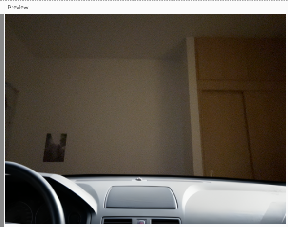
This is what the user actually experiences in my project. On my side, I wanted my project to simulate the experience of driving a manual car by providing complete control through the p5.js sketch. I added a static car window in the sketch that makes the users feel like they’re actually inside the car while controlling it remotely. Also, the sketch provides a gear box, allowing users to adjust the speed as if they are accelerating in a real car. The cool thing about this project is that it aims to seamlessly bring in a webcam, providing users with a live visual experience on p5.js. This goes beyond physical boundaries, allowing for easy remote control, even if the car is far away.
User Testing:
User 1 Testing: Project was not finalized
User 2 Testing: Final Project
Users Feedback:
- The two users generally demonstrated an ability to engage with the project without explicit instructions and they quickly grasped the basic mechanics for car movement.
- A good comment was about the game interface which is very simple and friendly. Another good comment was about the filter added to the video, which adds a non-realistic mood that suits the game.
- I think only one part of the project required additional explanation which is paying attention to how far is the car because it’s all wired connections so there is a risk of losing connection or laptop fall if it’s put, for example, on a table. For that particular issue, I think I should tell the user about it or maybe adding this instruction in the game sketch as well.
Implementation:
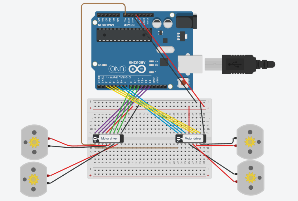
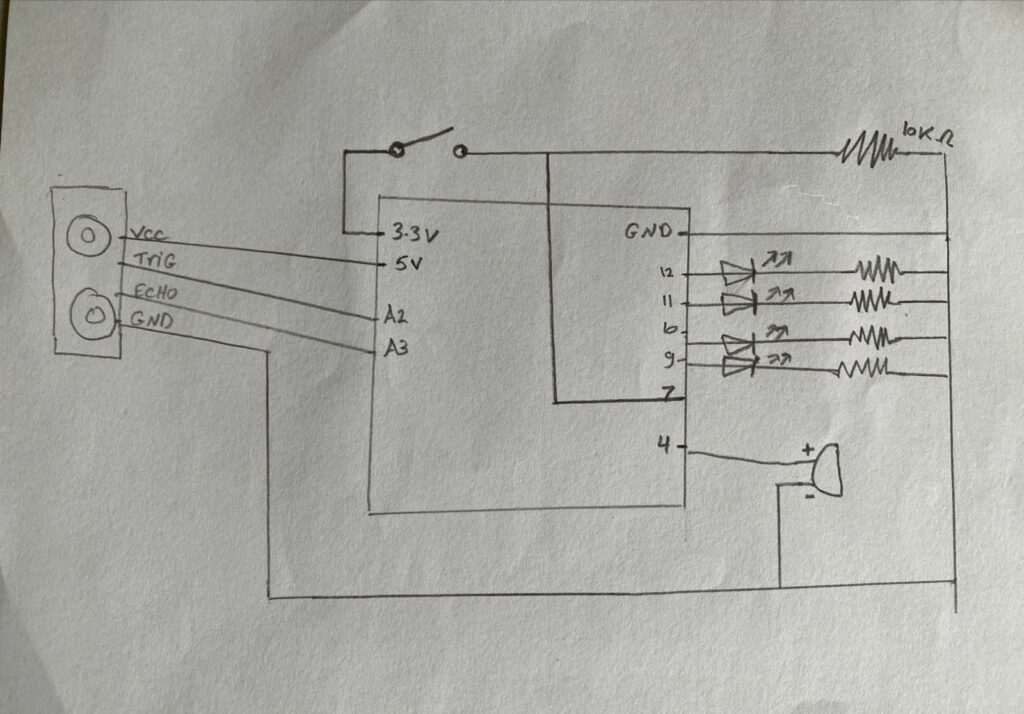
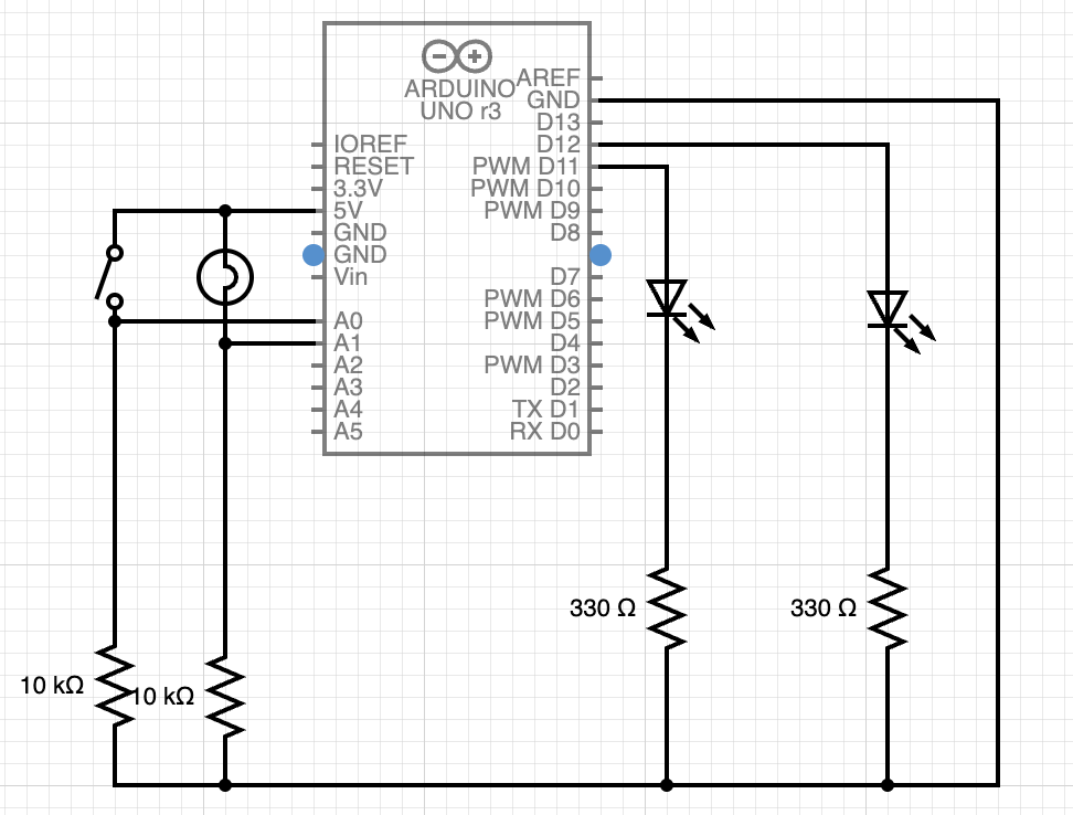
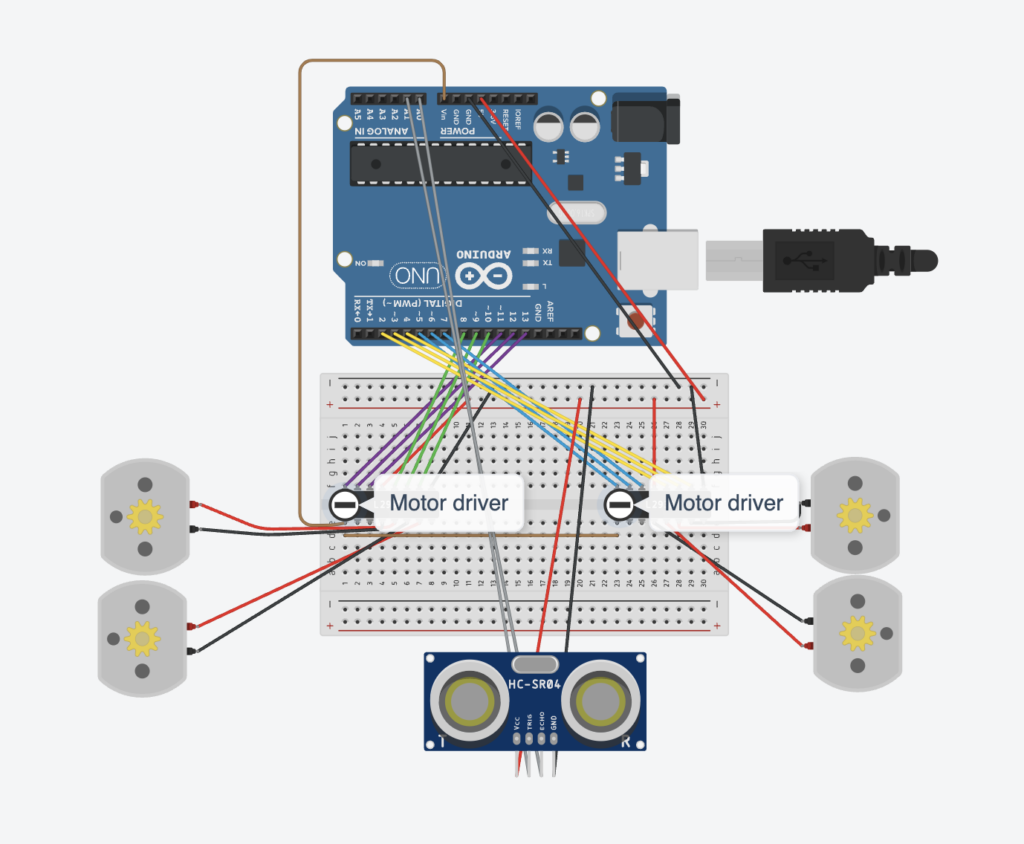
Circuit:
P5JS Code & Sketch:
P5JS code can be described as separate blocks of code which are as follows:
-
-
- Declaring global variables for the game and car control
- Pre-loading all the media used in the project (images, audio, …)
- Setting up the sketch and view the game state screen
- State1: start which is shown in the sketch below where the user chooses to start the game or show instructions.
- State2: Instructions which obviously guide the user
- State3: game where you experience driving
- State4: end screen where your score is displayed
-
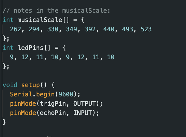
Arduino Code:
The code basically sets up the car functionality. The code starts with identifying the pins used in the circuit for the motor drivers and the ultrasonic distance sensor. Also, I created a separate function for each direction movement. Based on the data received from the sketch, a function is triggered.
//front left
const int ain1Pin = 13;
const int ain2Pin = 12;
const int pwmAPin = 11;
//back left
const int bin1Pin = 8;
const int bin2Pin = 9;
const int pwmBPin = 10;
//front right
const int cin1Pin = 7;
const int cin2Pin = 6;
const int pwmCPin = 5;
//back right
const int din1Pin = 2;
const int din2Pin = 4;
const int pwmDPin = 3;

const int TRIGGER_PIN = A0;
const int ECHO_PIN = A1;

//global
int speed = 0;

void setup() {
  Serial.begin(9600);
  pinMode(ain1Pin, OUTPUT);
  pinMode(ain2Pin, OUTPUT);
  pinMode(bin1Pin, OUTPUT);
  pinMode(bin2Pin, OUTPUT);
  pinMode(cin1Pin, OUTPUT);
  pinMode(cin2Pin, OUTPUT);
  pinMode(din1Pin, OUTPUT);
  pinMode(din2Pin, OUTPUT);
  pinMode (TRIGGER_PIN, OUTPUT);
  pinMode (ECHO_PIN, INPUT);
}

void loop() {

  // Check if data is available from p5.js
  if (Serial.available() > 0) {
    // Read the brightness value from p5.js
    speed = Serial.parseInt();
    int up = Serial.parseInt();
    int down = Serial.parseInt();
    int right = Serial.parseInt();
    int left = Serial.parseInt();
    if(up == 1){
        moveForward();
    }else if(down == 1){
        moveBackward();
    }else if(right == 1){
        moveRight();
    }
    else if(left == 1){
        moveLeft();
    }
    else{
        digitalWrite(ain1Pin, LOW);
        digitalWrite(ain2Pin, LOW);
        digitalWrite(cin1Pin, LOW);
        digitalWrite(cin2Pin, LOW);
        digitalWrite(bin1Pin, LOW);
        digitalWrite(bin2Pin, LOW);
        digitalWrite(din1Pin, LOW);
        digitalWrite(din2Pin, LOW);
    }
  }
  unsigned long duration;
  float distance;
  digitalWrite(TRIGGER_PIN, HIGH);
  delayMicroseconds(1000);
  digitalWrite(TRIGGER_PIN, LOW);
  duration = pulseIn (ECHO_PIN, HIGH);
  distance = (duration / 2.0) / 29.0;
  Serial.println(distance);
}

void moveForward(){
  analogWrite(pwmAPin, speed);
  analogWrite(pwmCPin, speed);
  analogWrite(pwmBPin, speed);
  analogWrite(pwmDPin, speed);
  digitalWrite(ain1Pin, HIGH);
  digitalWrite(ain2Pin, LOW);
  digitalWrite(bin1Pin, HIGH);
  digitalWrite(bin2Pin, LOW);
  digitalWrite(cin1Pin, HIGH);
  digitalWrite(cin2Pin, LOW);
  digitalWrite(din1Pin, HIGH);
  digitalWrite(din2Pin, LOW);
}

void moveBackward(){
  analogWrite(pwmAPin, speed);
  analogWrite(pwmCPin, speed);
  analogWrite(pwmBPin, speed);
  analogWrite(pwmDPin, speed);
  digitalWrite(ain1Pin, LOW);
  digitalWrite(ain2Pin, HIGH);
  digitalWrite(bin1Pin, LOW);
  digitalWrite(bin2Pin, HIGH);
  digitalWrite(cin1Pin, LOW);
  digitalWrite(cin2Pin, HIGH);
  digitalWrite(din1Pin, LOW);
  digitalWrite(din2Pin, HIGH);
}

void moveRight(){
  analogWrite(pwmAPin, 255);
  analogWrite(pwmBPin, 255);
  analogWrite(pwmCPin, 255);
  analogWrite(pwmDPin, 255);
  digitalWrite(cin1Pin, HIGH);
  digitalWrite(cin2Pin, LOW);
  digitalWrite(din1Pin, HIGH);
  digitalWrite(din2Pin, LOW);
  digitalWrite(ain1Pin, LOW);
  digitalWrite(ain2Pin, HIGH);
  digitalWrite(bin1Pin, LOW);
  digitalWrite(bin2Pin, HIGH);
}

void moveLeft(){
  analogWrite(pwmAPin, 255);
  analogWrite(pwmBPin, 255);
  analogWrite(pwmCPin, 255);
  analogWrite(pwmDPin, 255);
  digitalWrite(cin1Pin, LOW);
  digitalWrite(cin2Pin, HIGH);
  digitalWrite(din1Pin, LOW);
  digitalWrite(din2Pin, HIGH);
  digitalWrite(ain1Pin, HIGH);
  digitalWrite(ain2Pin, LOW);
  digitalWrite(bin1Pin, HIGH);
  digitalWrite(bin2Pin, LOW);
}

long microsecondsToCentimeters(long microseconds) {
  return microseconds / 29 / 2;
}
Communication between P5 and Arduino:
The Arduino C code basically receives data from the P5Js sketch and work accordingly. There are 5 variables received that controls the car movement: the four directions (up, down, left, and right) and the speed controlled by the gear box in the sketch. On the other hand, the P5JS sketch receives one value which is the distance of the ultrasonic distance sensor and checks for collisions.
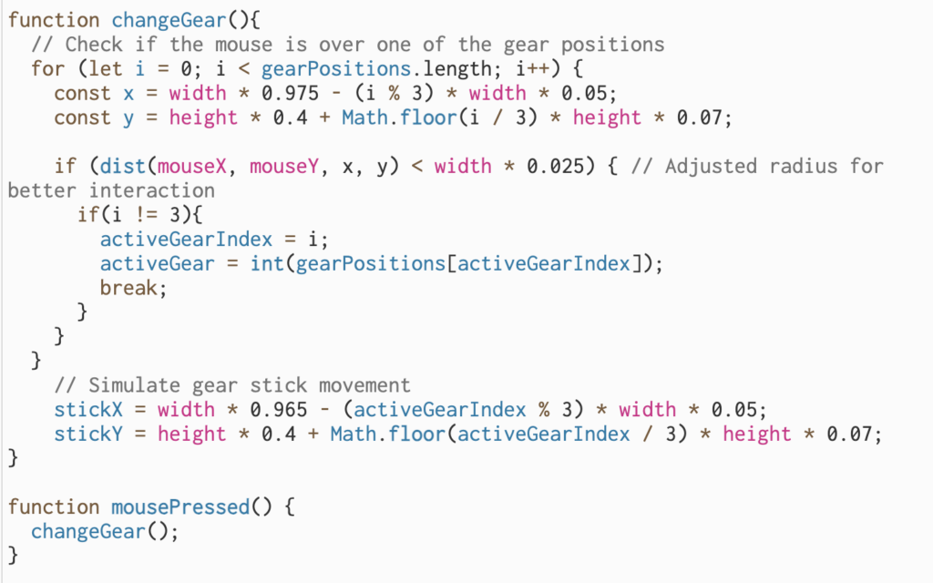
Parts I am proud of:
I am proud of the overall output of my project and that I got some hardware control in my skill set. I am particularly proud of two things: the visual design of my game and creating a gear box to control the car speed. For this project, I spent much time trying to improve the visual elements of my game whether through the static elements (car, gearbox, …) or dynamic video feed. I added a filter to my screen which I think it gives a nice effect that perfectly matches the overall experience. For the gear box, it was very challenging to make it and shift from one gear to another, but eventually, I figured it out. Here is the function that does so.
Future Improvements:
One thing that I want to improve in my project in the wired connection because it somehow limits this fun experience. One way is to use a bluetooth module for sending and receiving data. However, the wired connection was still required for connecting the webcam to the laptop and capturing the car view. I am not sure, but maybe there is a wireless webcam somewhere on Earth…