The Demogorgon by Abigail and Ahmed
Concept & Design
Initially, we wanted to create a simple art project using multiple servos to control panels. That was very short-lived. Our concept slowly went from a simple interactive art piece that looked pretty to an interactive monster called a Demogorgon from the Netflix series Stranger Things. We wanted to make something interesting that could catch users’ attention longer than an art piece. Since our Demogorgon was not going to necessarily be a game with a winning or losing outcome, we still had to figure out ways to make it more interactive. We took our assigned reading: Emotion & Design: Attractive Things Work Better by Don Norman into consideration and decided that in order to convey what we wanted we needed to make the Demogorgon come to life and make it something that is interesting to look at in addition to the code and interact itive component. To make both the interactive component and the Demogorgon fit nicely together, we decided to use certain scenes of the show to inspire the movements. In the show, the protagonist Eleven defeats a Demogorgon by putting her hand up since she has the ability to manipulate living beings however she wants through her hands. This inspired us to make it so the user is able to open the Demogorgon face flaps we build as their hand gets closer to them through a distance-measuring sensor. As we went along with our project, we realized how ambitious we were with our concept and simply tried our best to make it happen.
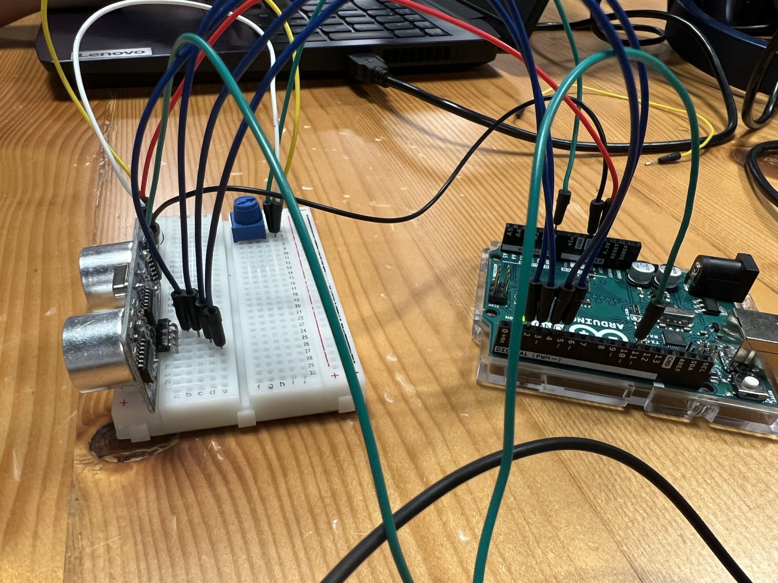
For our project, we used the ultrasonic distance measuring sensors, LED lights, flex sensors, 3-d printing, cardboard, wood, acrylic, and paint. Though we went through a lot of hiccups including but not limited to spending hours soldering cables we ended up not using, one of us going into isolation because of COVID-19, short circuits, and re-thinking our concept a few times… we kind of did it.
Interaction Design
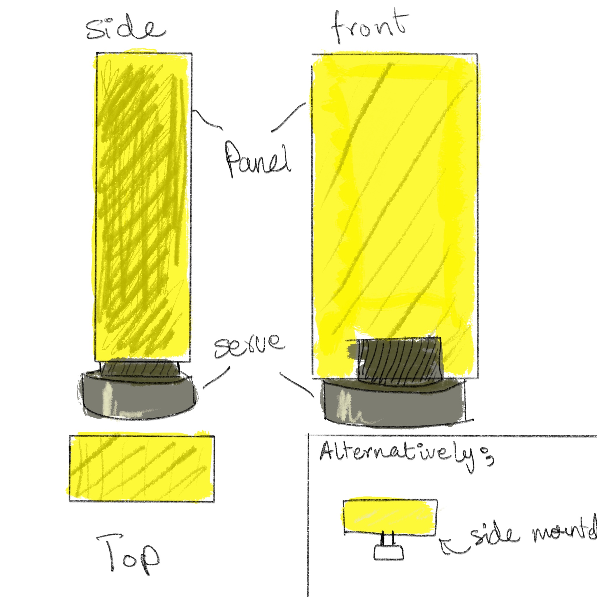
Physical
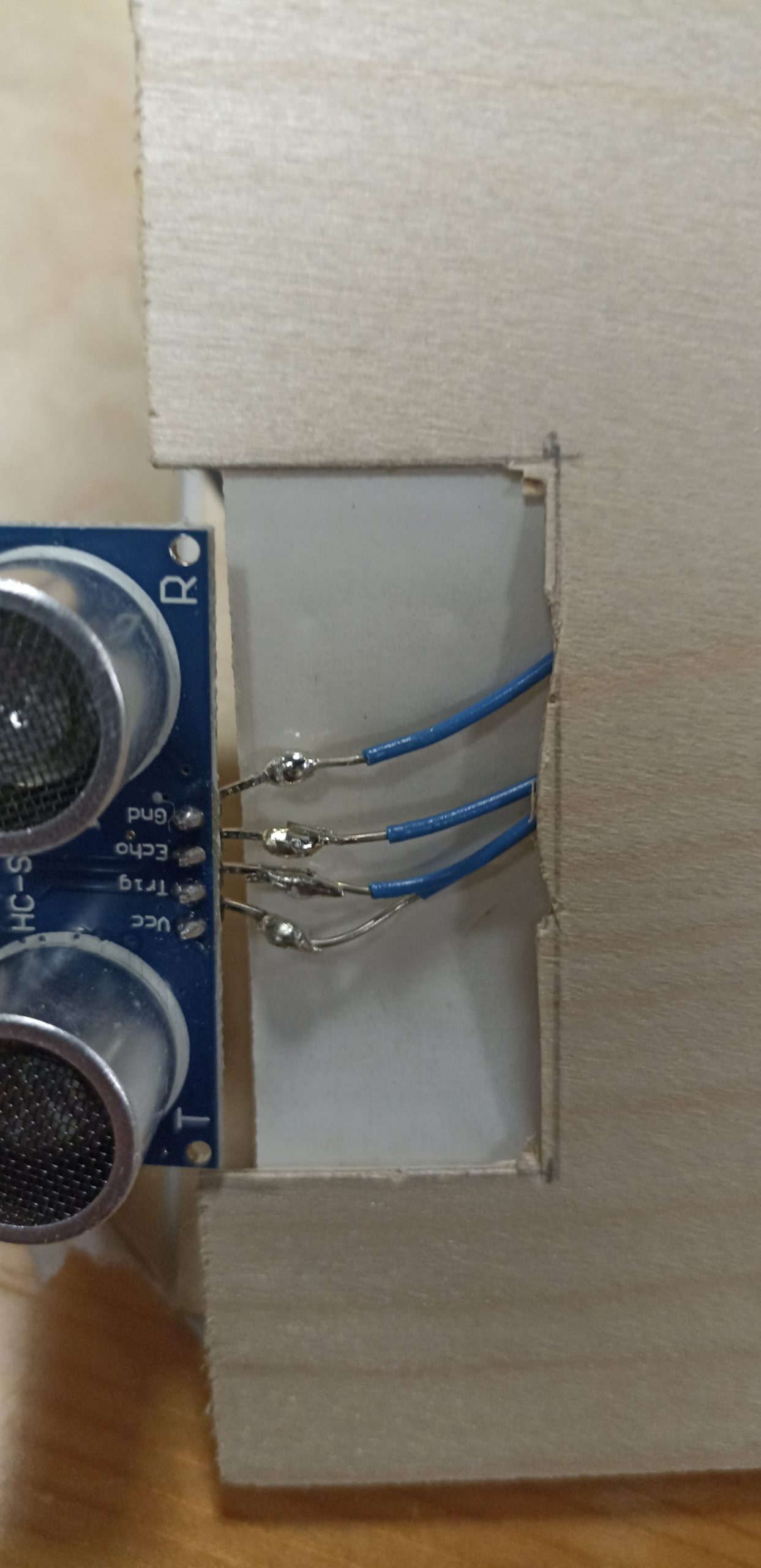
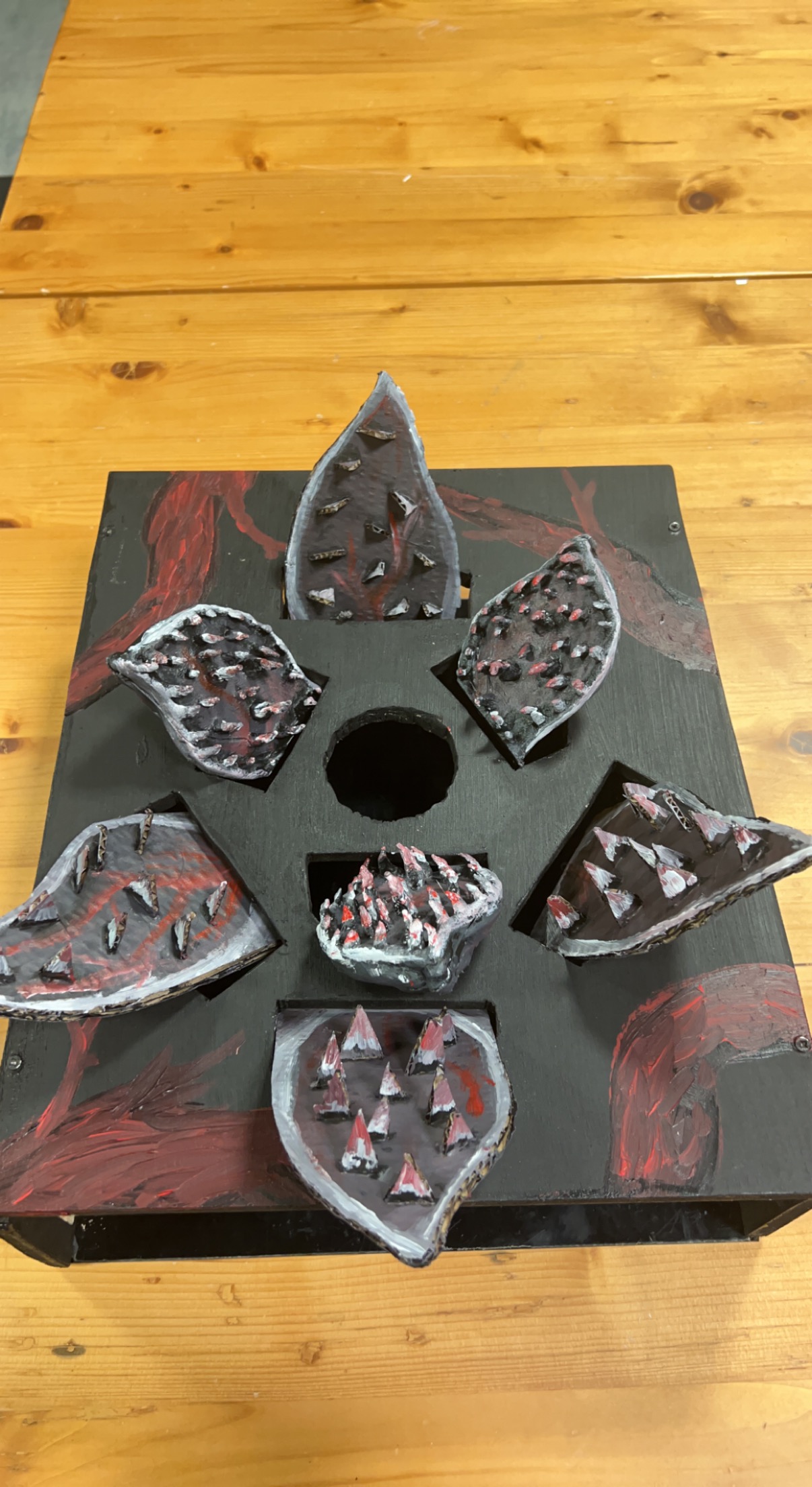
This was a very time-consuming aspect of project, especially since we really wanted it to make look as much as a Demogorgon’s head as possible with what we had. The wood that was available to us was pretty thick and we knew we had to cut holes in it to make openings for the 3-d printed and handmade Demogorgon flaps so it was going to take a long time to cut the wood and put everything together. Luckily, the woodshop was nice enough to let us borrow a Jigsaw so even though it was still a tedious process of drilling two holes where we wanted one hole for the flap to be and then using the Jigsaw to go in and follow the outline, it made it go a lot faster. We did this process seven times. For the flaps of the Demogorgon, at first, we 3-d printed three of them but it was taking a long time so for the last four we decided to build them out of cardboard for time’s sake. The 3-d printed ones still looked pretty cool though and definitely added an appeal to it, in our opinion. Plus, the different materials fit the Demogorgon vibe. We painted and added red and white for the skin tone. We also had to make longer cables to reach the Demogorgon flaps when our Arduino port is hidden beneath the box/head.
Arduino Code
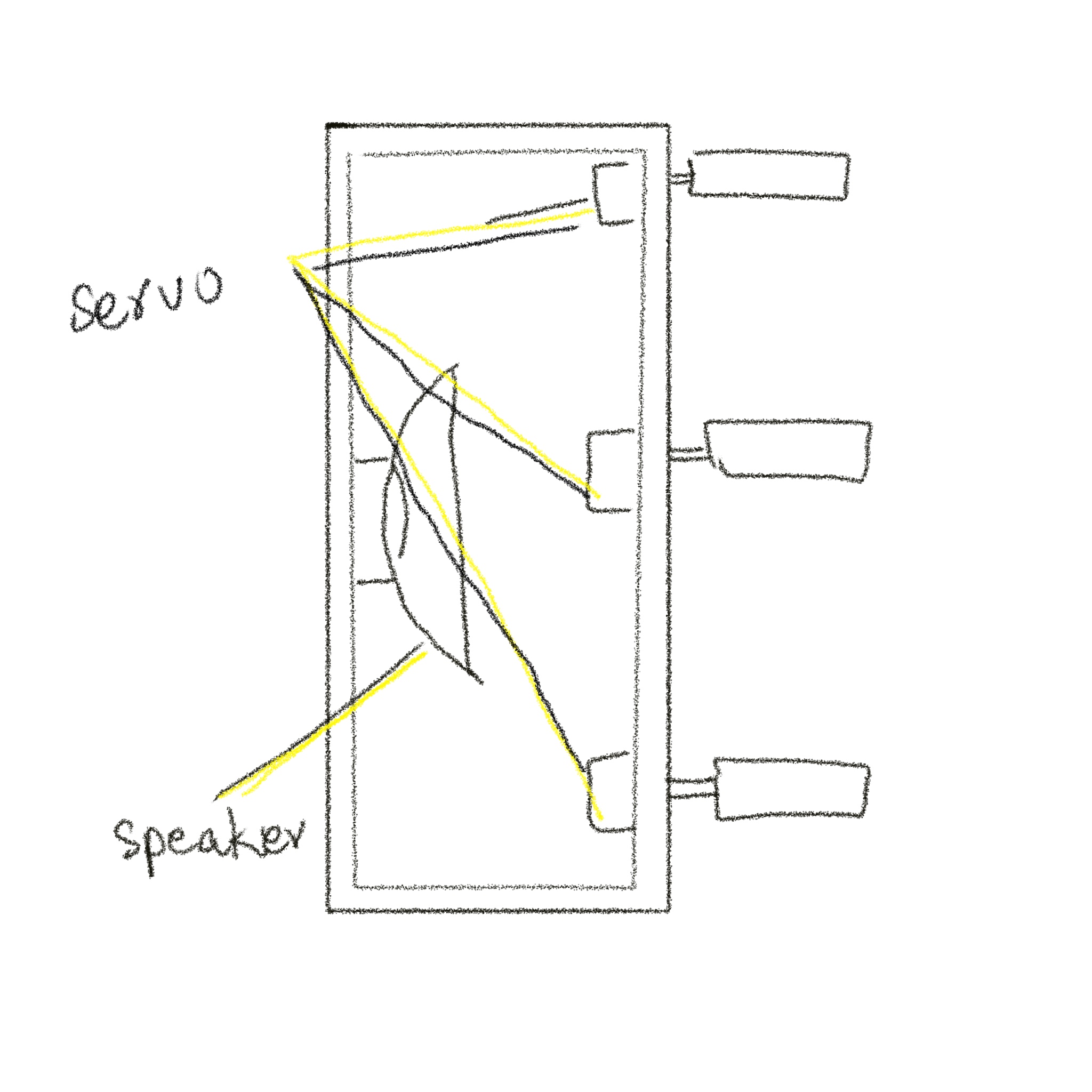
Our Arduino code controlled the flex sensors, server motors, and ultrasonic measuring sensor. The sens0rs were mapped to values from 0 to 180 and then output at different rates depending upon the configuration. The output rates helped stabilize the servo motors which were prone to jittering.
We used some sources for these pieces:
Code for the servo motors with Ultrasonic sensor:
// Clears the trigPin condition
digitalWrite(trigPin, LOW);
delayMicroseconds(100);
// Sets the trigPin HIGH (ACTIVE) for 10 microseconds
digitalWrite(trigPin, HIGH);
delayMicroseconds(100);
digitalWrite(trigPin, LOW);
// Reads the echoPin, returns the sound wave travel time in microseconds
duration = pulseIn(echoPin, HIGH);
// Calculating the distance
distance = duration * 0.034 / 2; // Speed of sound wave divided by 2 (go and back)
// Displays the distance on the Serial Monitor
distanceMapped = map(distance, 0, 70, 22, 180);
distanceMapped=constrain(distanceMapped, 30, 180); //this allows the output to stay between the constraints. without this it goes up to like a few thousand for some reason

int distanceMappedforOuter = distanceMapped + 10; // the outer petals will open wider, to give a flared look

myOuterServos.write(distanceMappedforOuter);
delay(75);
myInnerServos.write(distanceMapped);
delay (75);
Code to control servos with the Flex Sensors:
int OutsideFlexValue;
int InnerFlexValue;

int servoPositionInside;
int servoPositionOutside;

OutsideFlexValue = analogRead(OutsideFlexPin);
// delay(15); //adding slight delays to make it stable

InnerFlexValue = analogRead(InsideFlexPin);
// delay(15);

servoPositionOutside = map(OutsideFlexValue, 170, 500, 0, 180);  // need it to rest at a midwards position
servoPositionOutside = constrain(servoPositionOutside, 0, 180);
// int round10(int servoPositionOutside);

servoPositionInside = map(InnerFlexValue, 100, 360, 0, 180);
servoPositionInside = constrain(servoPositionInside, 0, 180);

// servoPosition = constrain(servoPosition, 45, 180); //for the servos that go beyond 180

myOuterServos.write(servoPositionOutside);
delay(75);
myInnerServos.write(servoPositionInside);
delay(75);
To reduce jittering the following line of code was added to constrain the servo motors from going beyond set parameters.
distanceMapped = map(distance, 0, 70, 22, 180);
distanceMapped=constrain(distanceMapped, 30, 180); //this allows the output to stay between the constraints. without this it goes up to like a few thousand for some reason
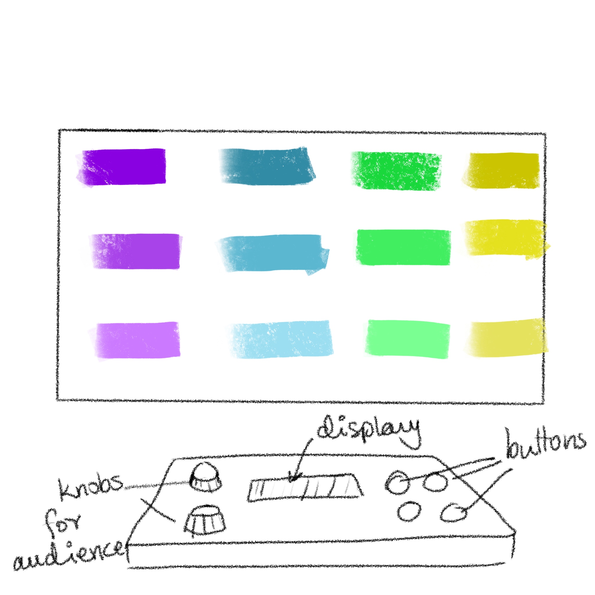
p5.js Code
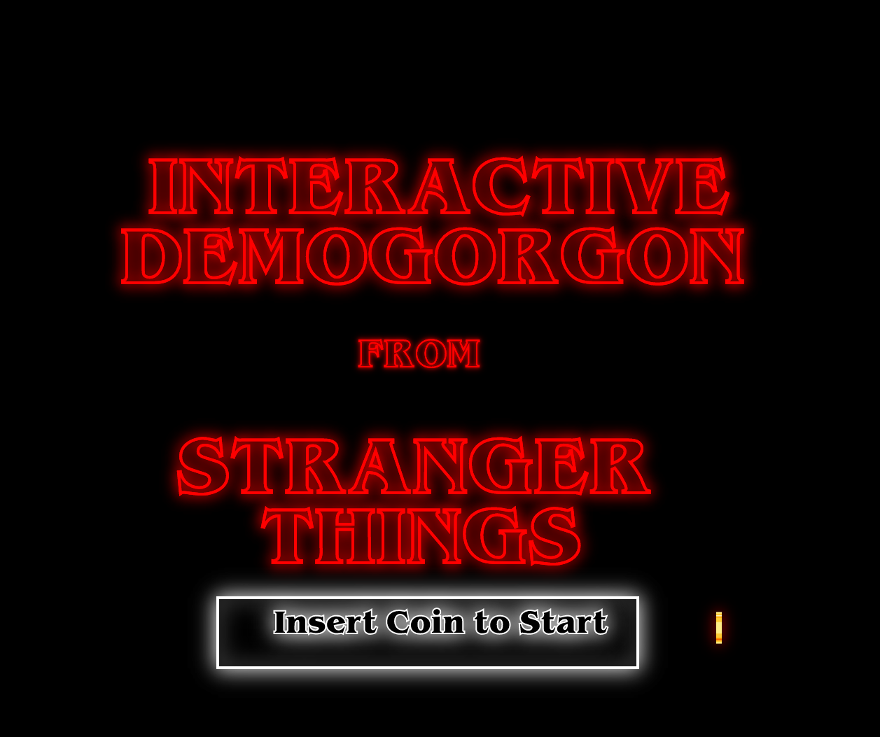
Our p5.js code focused on the screen that the user would see and use to interact with our Demogorgon. We used the game state and included a starting screen followed by an introduction and instruction screen. We realize not everyone may know what a Demogorgon is or have watched Stranger Things, so we made it feel an arcade game you would go up to, get an introduction and instructions for, and start playing around with it whether or not you fully grasp the inspiration behind it.
There was an issue that we couldn’t quite figure out. After adding the second sound, the audio would start glitching after a while. At first, we thought it was just the sound so we tried it out with different sounds but no luck. When we decided to search if there was a solution or if the code was wrong, we found a thread from 2020 that discussed how the newest versions of p5.js have audible distorted effects on Chrome and there is no fix yet. The audio just keeps getting distorted and eventually the window shuts down and you have to refresh the page.
The p5js code can be accessed on Abigail and I’s p5js sketches directory on the p5js website.
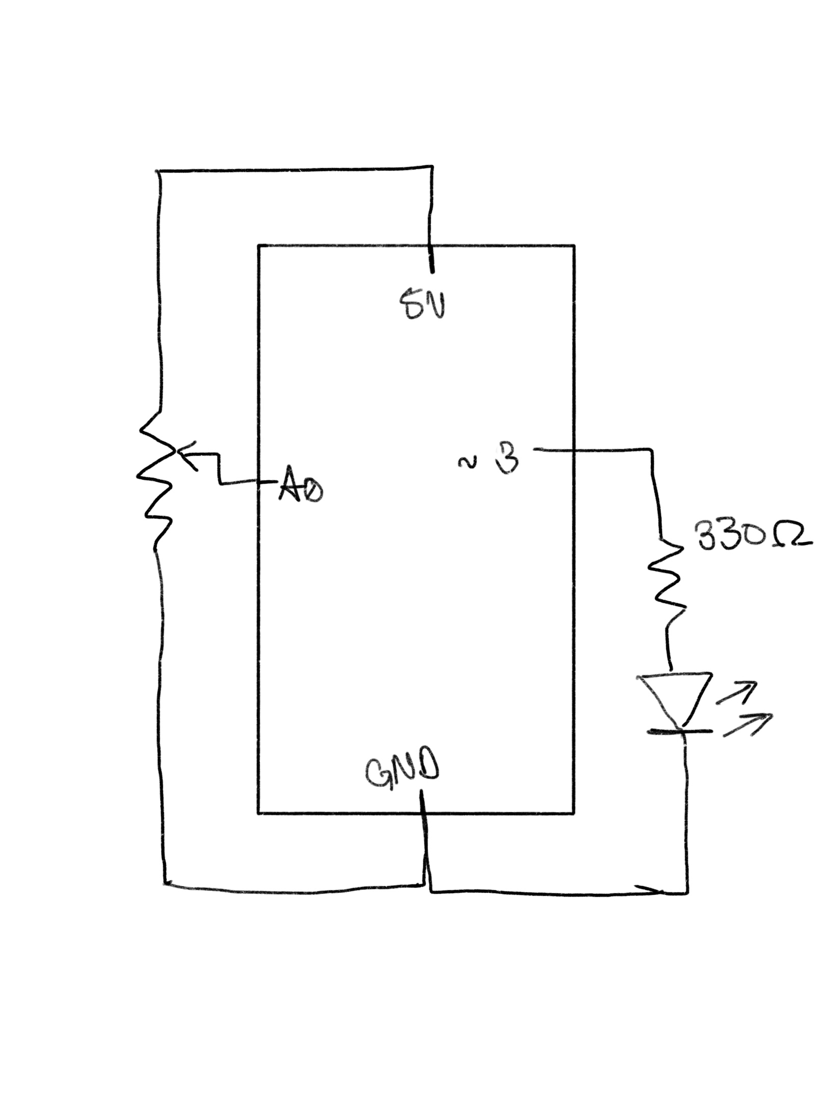
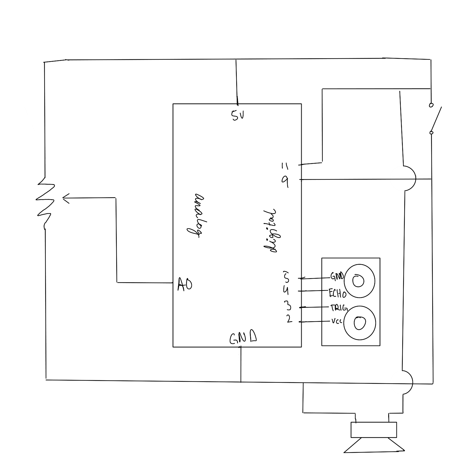
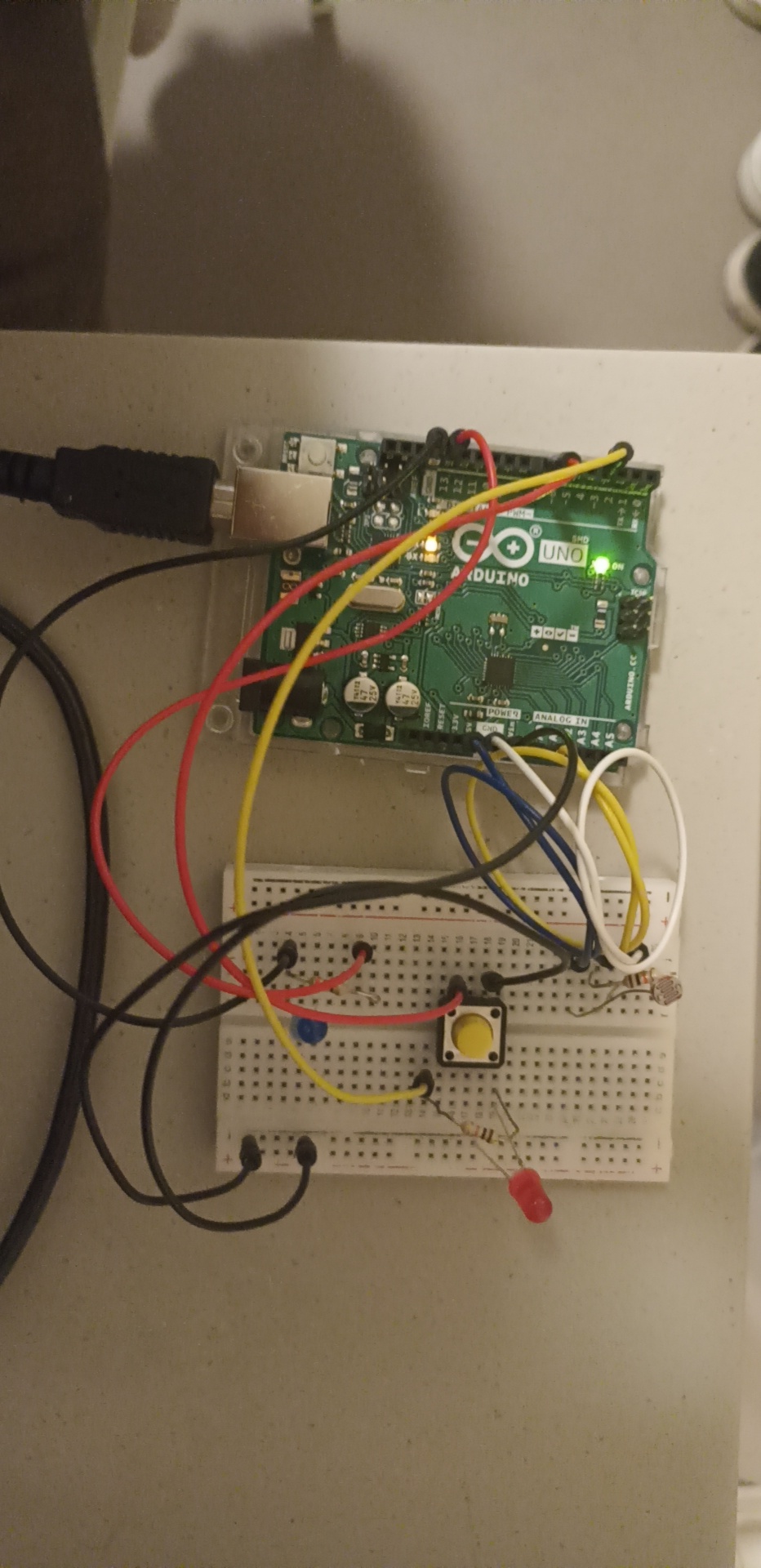
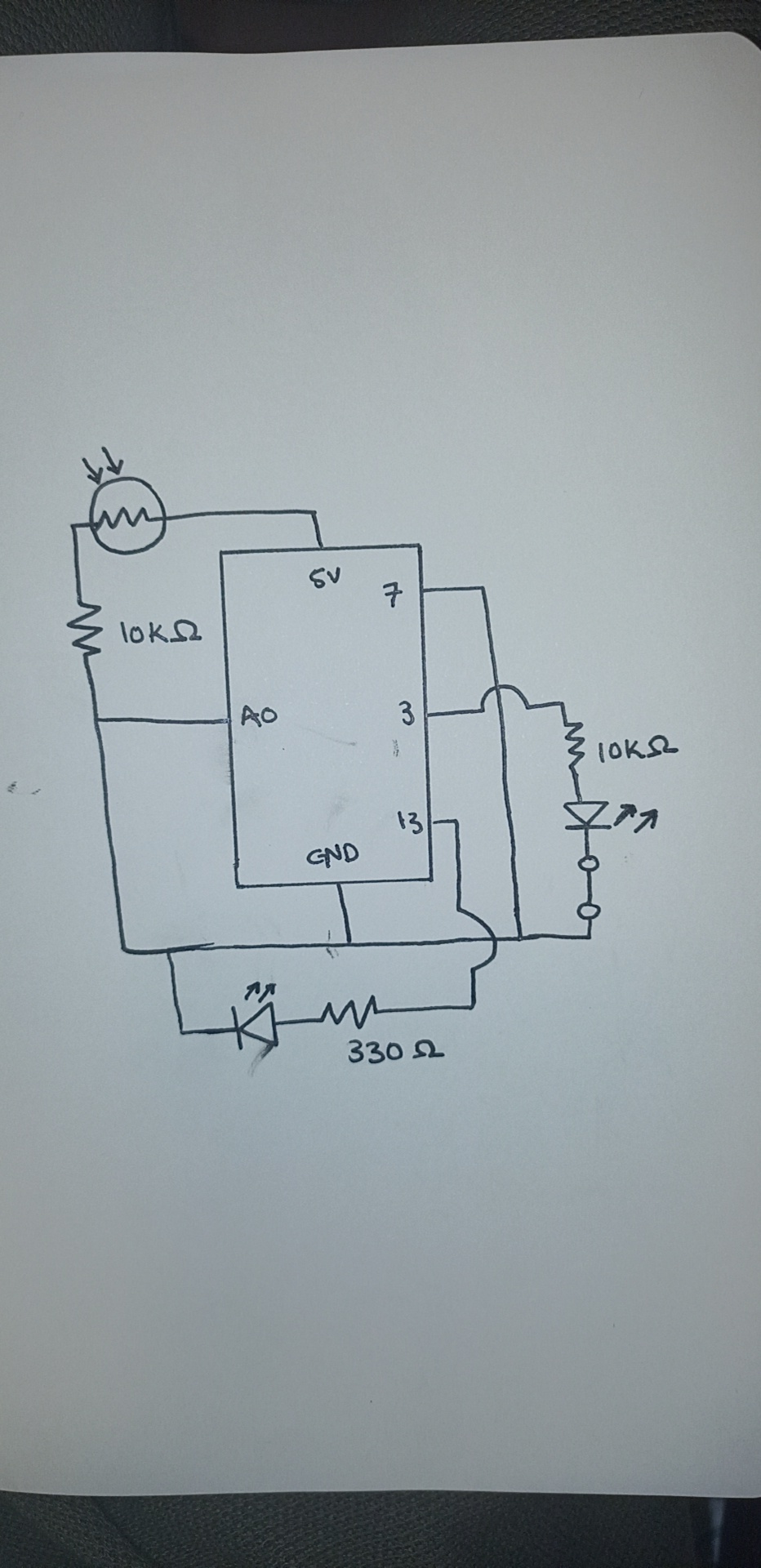
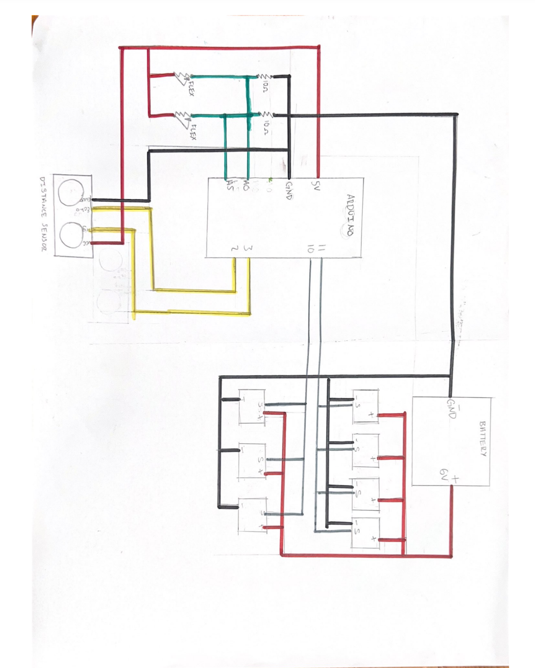
Circuit Diagram for the Project:
Since our project was rather complicated and needed a lot of cables, we decided to draw a schematic for it.
Problem(s) 🙁
Though we knew what needed to be communicated between the Arduino and p5.js, it worked only sometimes. The problems started when we started off by checking out the Arduino MEGA from the IM Lab and tailoring our code to it. However, since we got an extension past the last day to return items to the IM Lab due to reasons neither of us could control, we had to switch back to the Arduino we received in our kit. For some reason what we had did not work after that and we had to figure out why. We switched up the code again but only some parts of it would work and only sometimes as p5.js kept shutting down and the serial connection kept disconnecting. We tried to ask for help through friends and Facebook groups. No one was able to help us though and as we ran out of time we accepted our fate. The Demogorgon beat us (sorta).
Some testing and progress videos:
Testing the Flex sensors interfaced with the servo motors:
Testing the ultrasonic distance sensor interfaced with the servos:
Problems that we ran into and how we tried to solve them:
- The first problem we ran into pretty early on was a jittering in the servo motors that could not be controlled. The jittering would make the servos move even when the code was not running. After some debugging, we realized that the problem originated with the 5v supply on the main board, and switching the servos to an external power source would reduce it. It could be made smoother by adding another earth wire connected to one of the unused GND pins
- Another problem we ran into was the 3d printing of some of the parts. The models we had used were pulled off the internet and were supposed to be printed within a few hours but the first 3 iterations were all just a mess of melted filament since the model would move around. After consulting the lab assistants we realized scraping the surface of the building area of the printer solved the issue immediately.
- A bug that we ran into while working on the Arduino-p5js serial communication was that the communication would halt and spout an error ‘Failed to open serial port’. We realized that this could be fixed most of the time by closing the serial monitor on the IDE. However, at one point it persisted despite restarting, and according to some forums, it was a problem with incompatible drivers that plague computers with versions of Windows later than 10.
- Another bug that we ran across that caused us the most trouble was that the p5js terminal would not work or crash periodically after adding sound effects that were to be played on the terminal. We could not find a viable solution to this problem.
- We did not realize until the last moment that there were in fact some subtle differences between how Arduino mega and uno work. Other than the size and ram, there is also a difference in how we set up the ultrasonic distance sensor by following this tutorial. There were other differences too that for some reason broke the code when we tried running it on the Uno however we cannot seem to locate the exact piece of code that caused it.
Future Improvements:
- I think we focused on Professor’s warning that the physical component was going to take a really long time too much. Our concept depended a lot on being appealing to the audience so we wanted to make sure we made our Demogorgon look really good and spooky. However, we spent so much time on it considering the limited time we had that we did not think about how buggy the code would be considering everything we were trying to make it do at once.
- Figure out a more stable way for communication between p5js and Arduino.
- Use a stable operating system that causes the least amount of problems with regard to drivers
- Use a stable search engine to run p5js smoothly
- Employ a better and more rigorous documentation method along the progress of future projects to create a seamless reference system in case of mistakes. We spent way too much time trying to debug without knowing what resources I had accessed before or how we had implemented stuff.
Project Reflection:
This project was really challenging yet somewhat rewarding. I think personally, I would like to spend more time researching the project before actually starting with it. The technique of ‘forcing’ a project or completing it by brute force is not something that can be accomplished with such projects. This project also gave me experience with interfacing Arduino boards with p5js. And showed me how important it is to start early with developing a code that can work seamlessly, especially with tools that are relatively new to me, and are already known to have caused problems.
The project was also an opportunity for me to gain more knowledge and technical know-how from the Professor who has been teaching people about creative robotics for a long time. I was able to pick his brains but failed to capitalize on him as an incredible resource towards the final stretch which led to failure to achieve a favorable final project. It made me realise how important it was to reach out when there is a problem hampering progress.
Moreover, the project allowed me to push my boundaries to the extreme. Not only was it intellectually strenuous, requiring a great amount of technical know-how and problem-solving abilities but also physically straining and intensive. I am extremely disappointed in not being able to assemble the final project in a way that was, well, final. However, this project has only given me more drive to try and learn more about p5js, and Arduino and how these two tools can be merged to create working machines beyond their apparent limits.