Final – ☆ Photo Roulette ☆

Concept and Inspiration

My concept and inspiration for the final project came from a wish to make something related to cameras/photo-taking/film. Initially, I wanted to make a “camera on wheels”, but then I realized the camera lens would be on my laptop and therefore couldn’t add wheels to it, haha. So, I changed my idea but stuck with the camera concept.

I really enjoy taking photo booth pictures. In fact, I will always push my friends to take them with me if I see a photo booth anywhere. I have collected these grid images from all around the world – Beirut, Abu Dhabi, Paris, New York, Madrid, London, Dubai… And I still have them all saved. They are, to me, a beautiful way of keeping memories in a non-digital fashion, which we tend to towards these days with our phones. I also enjoy the photo booth app on the phone, but the grid layout that results is not the same as a typical, “retro” photo booth.

So, I decided to create a photo booth, which generates four images as a vertical grid!

How to use it

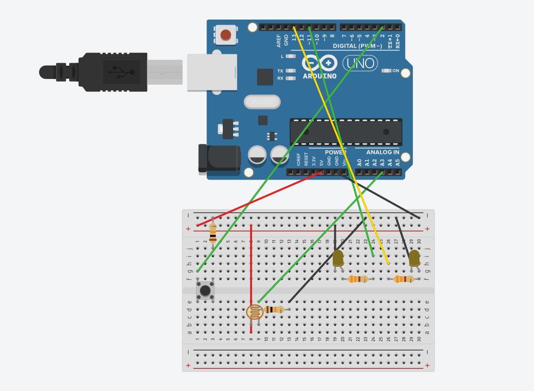
This project is composed of two parts: my laptop with a p5 sketch, and a “camera” I built out of cardboard, inside which there is the Arduino and breadboard. The p5 sketch begins with a start page, that states “photo booth”. There are also instructions: the first step is to click on the screen (when the images are downloaded, the user needs to press on the screen to return to the chrome page); the second step is to press record on the camera to start taking the images.

Once the record button on the camera is pressed, a message is sent from Arduino to p5 to start the photo booth session. Simultaneously, a LED turns on for 20 seconds (which is the length of each session). The four images are taken at five second intervals, with a countdown starting at three seconds. After the twenty seconds have passed, the images are downloaded as a grid, and the user can airdrop it to their phone. Moreover, when the images are done, the start page is displayed again.

Codes


To achieve this, I created a short code on Arduino and a longer one on p5.

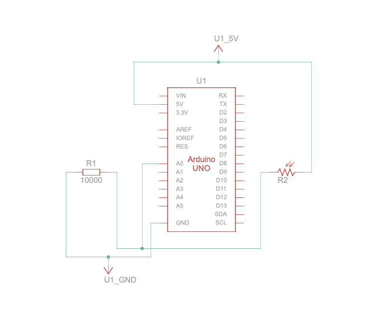
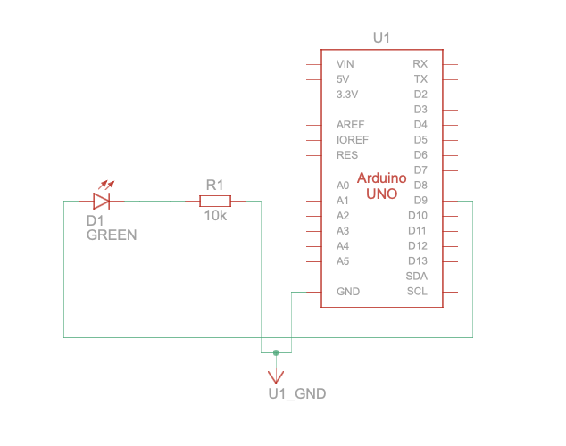
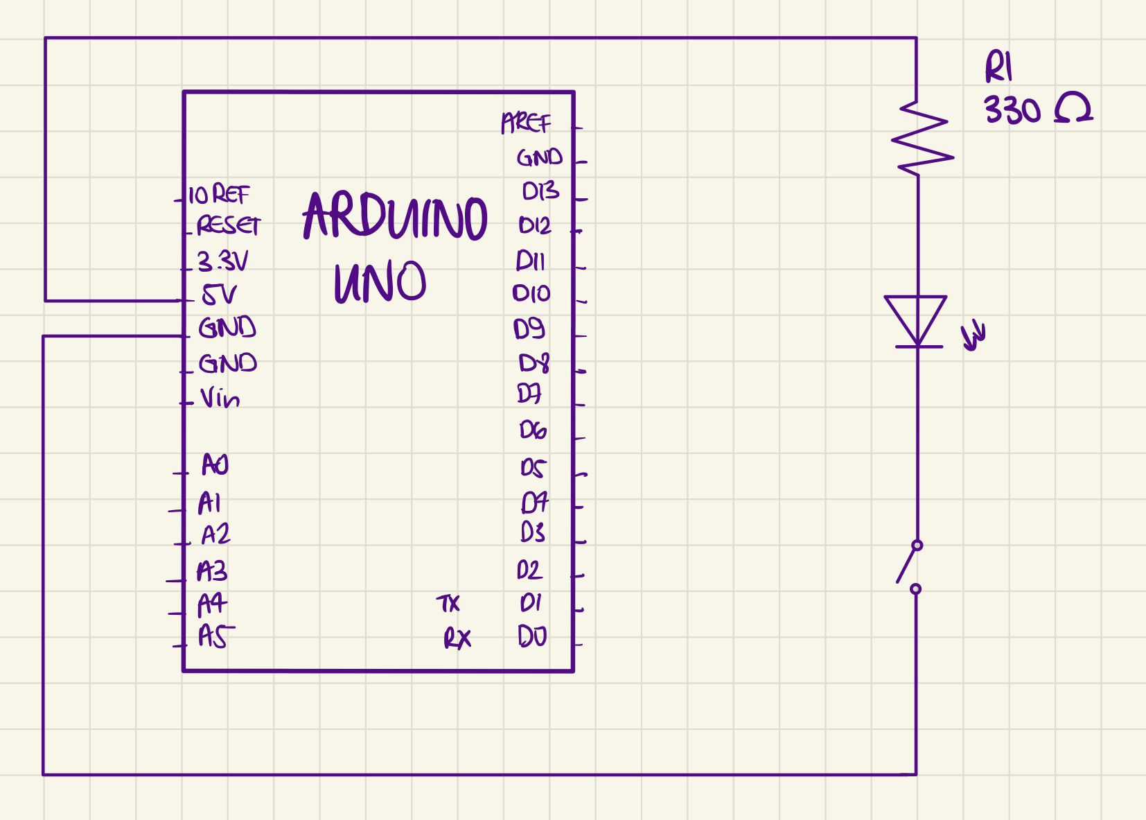
Arduino code & circuit

const int BUTTON_PIN = 2;
const int LED_PIN = 13;

bool ledState = false;
int lastButtonState = LOW;
unsigned long startTime = 0; // variable to store the time the button was pressed
const unsigned long interval = 20000; // interval of 20 seconds to indicate when the LED must turn off

void setup() {
  pinMode(BUTTON_PIN, INPUT);
  pinMode(LED_PIN, OUTPUT);
  Serial.begin(9600);
}

void loop() {
  int reading = digitalRead(BUTTON_PIN);

  // checking if the button was pressed
  if (reading != lastButtonState) {
    lastButtonState = reading;
    if (reading == HIGH) {
  
      ledState = true; // turn LED on
      digitalWrite(LED_PIN, HIGH);
      Serial.println("START"); // send "START" to p5
      startTime = millis(); // start recording the time of button press
    }
  }

  // checking if 20 seconds have passed since the button was pressed
  if (ledState && (millis() - startTime >= interval)) {
    ledState = false; // turn LED off
    digitalWrite(LED_PIN, LOW);
    Serial.println("STOP"); // when 20 seconds have passed, send "STOP" to p5
  }
}

p5 code snippets

→ a function to start the countdown between each image.

function startCountdown() {
  countdownValue = 4; // start the countdown with "nothing"
  clearInterval(countdownTimer); // clear the existing timer, necessary after the first image is taken after the sketch is played
  countdownTimer = setInterval(() => {
    countdownValue--;
    if (countdownValue === 0) {
      // when count is down to 0
      clearInterval(countdownTimer); // stopping the timer
      captureImage(); // capturing an image after the countdown
      countdownValue = 4; // resetting the countdown value back to 4
      setTimeout(startCountdown, interval); // 1-second delay before restarting the countdown
    }
  }, interval); // repeat the function at 1-second intervals
}

→ a function to capture and save the images, with a sound that plays when each image is taken.

function captureImage() {
  if (recording) {
    sound1.play(); // playing the sound when an image is captured

    images[captureIndex] = videos[captureIndex].get(); // capturing the image from each of the four video feeds
    captureIndex++;

    // when the four images are taken, recording is stopped and images are saved as a grid
    if (captureIndex >= 4) {
      stopRecording();
      saveImages();
    }
  }
}

→ determining the countdown value which is then displayed (3, 2, 1 only).

if (recording && countdownValue <= 3 && countdownValue > 0) {
  fill(255);
  textSize(200);
  textAlign(CENTER, CENTER);
  text(countdownValue, width / 2, height / 2);
}

→ function to start recording, which is later activated when the button of the camera is pressed, in a “START” state.

function startRecording() {
  if (!recording) {
    recording = true;
    captureIndex = 0;
    images = [null, null, null, null]; // reset the images array to clear previous session
    clearInterval(countdownTimer); // clear the timer from the previous session

    // clearing the video feeds
    for (let i = 0; i < 4; i++) {
      videos[i].hide(); // hide the video to clear the old feed
      videos[i] = createCapture(VIDEO); // create a new video capture
      videos[i].size(width / 3, height / 3); // set size for each video feed
      videos[i].hide(); // hide the video feed
    }

    startCountdown(); // start the countdown before the first image is captured
  }
}

→ function to stop recording, which is activated by the “STOP” message received by Arduino after the twenty seconds have passed.

// function to stop recording
function stopRecording() {
  print("Recording ended");
  if (recording) {
    recording = false;
    clearInterval(countdownTimer); // clear the countdown timer completely
  }
}

→ function to read the serial data from Arduino.

// read serial data from arduino
function readSerial(data) {
  if (data != null) {
    if (data == "START") { // when data from arduino is "START"
      displayStartPage = false; // switch to the photo booth page
      startRecording(); // start recording
    } else if (data == "STOP") { // when data from arduino is "STOP"
      displayStartPage = true; // display start page
      stopRecording(); // stop recording
    }
  }
}


Sketch


And here is a link to the full screen sketch:

https://editor.p5js.org/alexnajm/full/LVOvvvioq

What I am proud of

I am particularly proud of finally being able to understand how serial communication works. For me, I had a hard time processing it in practice, although in theory it did make sense. Applying it for this project which I made from scratch, as compared to the exercises we did in class, enabled me to better grasp the concept of serial communication.

Additionally, I am proud of how this project has evolved. I had a few ideas in between which truly were not challenging enough. I am not saying that this project is super complex, but it definitely took time and effort to try and understand how everything works in order to achieve this final result.


Challenges

I encountered multiple challenges, first, creating serial communication from scratch. Again, it was a bit hard for me to apply the concepts.

Another challenge was getting the feeds and countdown to reset after each session. At first, the images from the previous session remained on the feeds, which means the user couldn’t see a live version but only the images taken. Gladly, I was able to figure it out – same for the countdown.


Areas for future improvement

Eventually, I would like to create a better design for the p5 sketch. As of now, I feel like it’s a bit… bland.

I would also like to try to incorporate filters, which the user can choose from before taking the images. This was a bit hard as the images cannot be downloaded with the filter, and I did not want the grid to look different than the images displayed on the sketch.


References

https://p5js.org/reference/#/p5/createCapture

https://learn.digitalharbor.org/courses/creative-programming/lessons/using-timers-in-p5-js/


IM Showcase Documentation

Assignment #12 – Code – ☆In-Class Exercises☆

Exercise 1

For this exercise, we used a photosensor to control the x position of an ellipse in p5. The more light the photosensor reads, the further right the ellipse’s position is.

Demo:

Exercise 1 Video

Codes:

p5 –

let circlePosition = 100;
function setup() {
  createCanvas(400, 400);
  textSize(18);
  fill(243,213,205);
  text("Press the space bar to connect port", width / 2, 60);
}
function draw() {
  background(176, 16, 50);
  textSize(18);
  fill(243,213,205);
  text("Press the space bar to connect port", 60, 60);
  ellipse(circlePosition, height / 2, 70, 70);
}
// Function to set up the serial connection
function keyPressed() {
  if (key == " ") {
    setUpSerial();     
  }
}
// Function to read the data from serial port
function readSerial(data) {
  // Check if data received is not null
  if (data != null) {
    // Mapping the data to 0-400 and sets it as X position of the circle
    circlePosition = map(int(data), 0, 1023, 0, 400);
  }
}

Arduino –

void setup() {
  Serial.begin(9600); // Begin serial communication 
}
void loop() {
  int sensor = analogRead(A0);
  delay(5);
  Serial.println(sensor);
 
}

Circuit:

Exercise 2

For this exercise, we created a gradient on p5 that goes from green to black along the y-axis. When the mouse is on the highest point of the canvas, meaning at the greenest point, the LED is the brightest. The further the mouse goes down towards the black, the darker it gets.

Demo:

IMG_2972

Codes:

p5 –

function setup() {
  createCanvas(400, 400);
  textSize(20);
}

function draw() {
  // Gradient background from green to black
  setGradient(0, 0, width, height, color(0, 255, 0), color(0));


  if (!serialActive) {
    fill(255);
    text("Press space bar to select port", 60, 60);
  } else {
  }

  // Change brightness of LED based on mouse position
  let brightness = map(mouseY, 0, width, 255, 0);

  // Send the brightness value to Arduino
  if (serialActive) {
    let sendToArduino = brightness + "\n";
    writeSerial(sendToArduino);
  }
}

// Function to draw a gradient background
function setGradient(x, y, w, h, c1, c2) {
  noFill();
  for (let i = y; i <= y + h; i++) {
    let inter = map(i, y, y + h, 0, 1);
    let c = lerpColor(c1, c2, inter);
    stroke(c);
    line(x, i, x + w, i);
  }
}

// Function to begin serial connection
function keyPressed() {
  if (key == " ") {
    setUpSerial();
  }
}

function readSerial(data) {
  if (data != null) {
    serialActive = true;
  }
}

Arduino –

int ledPin = 9; 
int brightness = 0; 

void setup() {
  Serial.begin(9600);
  pinMode(LED_BUILTIN, OUTPUT);
  pinMode(ledPin, OUTPUT);
  digitalWrite(ledPin, LOW); // Starts with LED off
  while (!Serial) { // Wait for serial connection 
    delay(500);
  }
  Serial.println("Arduino initialized"); 
}

void loop() {
  if (Serial.available() > 0) {
    brightness = Serial.parseInt(); // Read brightness value
    analogWrite(ledPin, brightness);
    Serial.read(); 
  }
  digitalWrite(LED_BUILTIN, LOW); // LED off when there is no data
}

Circuit:


Exercise 3

For this exercise, we established bidirectional communication between the Arduino and the p5 sketch, enabling real-time interaction between physical input (potentiometer) and visual output (LED indication) synchronized with the simulation on p5.

The Arduino code reads data from a potentiometer connected to analog pin and sends it to the p5.js sketch. It also receives position data from the p5.js sketch via serial communication and controls an LED connected to pin 9 accordingly. The setup() function initializes serial communication and sets pin modes for the LED, potentiometer, and built-in LED. It initiates a handshake with the p5.js sketch by sending a starting message until it receives data from the serial port.

Demo:

Codes:

p5 –

let velocity;
let gravity;
let position;
let acceleration;
let breeze;
let drag = 0.99;
let mass = 50;
let heightOfBall = 0;
function setup() {
  createCanvas(640, 360);
 
  noFill();
  position = createVector(width/2, 0);
  velocity = createVector(0,0);
  acceleration = createVector(0,0);
  gravity = createVector(0, 0.5*mass);
  breeze = createVector(0,0); 
}
function draw() {
  background(215);
  fill(0);
  
  if (!serialActive) {
    text("Press space bar to connect Arduino", 50, 60);
  }
  else 
  {
  
  applyForce(breeze); 
  applyForce(gravity);
  velocity.add(acceleration);
  velocity.mult(drag);
  position.add(velocity);
  acceleration.mult(0);
  ellipse(position.x,position.y,mass,mass);
    
  if (position.y > height-mass/2) {
      velocity.y *= -0.9;  
    
      position.y = height-mass/2;
    
    heightOfBall = 0;
    
    } 
    else {
      heightOfBall = 1;
    }
  }
}
function applyForce(force){
  // Newton's 2nd law: F = M * A
  // or A = F / M
  let f = p5.Vector.div(force, mass);
  acceleration.add(f);
}
function keyPressed() {
  if (key == " ") {
    // important to have in order to start the serial connection!!
    setUpSerial();
  }   
  else if (key=='b'){
    mass=random(15,80);
    position.y=-mass;
    velocity.mult(0);
  }
}
// this callback function
function readSerial(data) {
    ////////////////////////////////////
    //READ FROM ARDUINO HERE
    ////////////////////////////////////
  
     if (data != null) {
    // make sure there is actually a message
    
    let fromArduino = split(trim(data), ",");
    
       // if the right length, then proceed
    if (fromArduino.length == 1) {
//sensor value is the input from potentiometer
      let sensorVal = int(fromArduino[0]);
      
//potentiometer value ranges from 0 - 1023
//for values less than 400,wind blows to right
      if (sensorVal < 400){
        breeze.x=1
      }
//if value between 400 and 500, wind stops so ball stops
      else if(sensorVal >= 400 && sensorVal < 500){
        breeze.x = 0
      }
//if value greater than 500, wind blows to left
      else {
        breeze.x = -1
      }
          //////////////////////////////////
          //SEND TO ARDUINO HERE (handshake)
          //////////////////////////////////
    }
//height of ball sent to arduino to check if ball on floor or not
    let sendToArduino = heightOfBall  + "\n";
    writeSerial(sendToArduino);
  }
}

Arduino –

const int poten_pin = A5;
const int ledPin = 9;
void setup() {
 Serial.begin(9600); // Start serial communication at 9600 bps
 pinMode(LED_BUILTIN, OUTPUT);
 pinMode(ledPin, OUTPUT);
 pinMode(poten_pin, INPUT);
 // start the handshake
 while (Serial.available() <= 0) {
   digitalWrite(LED_BUILTIN, HIGH); // on/blink while waiting for serial data
   Serial.println("0,0"); // send a starting message
   delay(300);            // wait 1/3 second
   digitalWrite(LED_BUILTIN, LOW);
   delay(50);
 }
}
void loop()
{
 // wait for data from p5 before doing something
   while (Serial.available())
   {
     digitalWrite(LED_BUILTIN, HIGH);
     digitalWrite(ledPin, LOW);
//read the position of ball from p5
     int position = Serial.parseInt();
  
     if (Serial.read() == '\n') {
       // Read potentiometer value
     int sensorValue = analogRead(poten_pin);
     //send value to p5
     Serial.println(sensorValue);
     }
//if ball is touching the ground i.e. height is zero, turn LED on
     if (position == 0)
     {
       digitalWrite(ledPin, HIGH);
     }
     else{
       digitalWrite(ledPin, LOW);
     }
   }
     digitalWrite(LED_BUILTIN, LOW);
   }

Circuit:

Assignment #11 – Midterm Idea

For the final project, I am thinking of making a camera on wheels. I was inspired by a panther dolly, which consists of a track and a mount with wheels on which the camera goes. Essentially, there is someone pushing the dolly when scenes require the camera to sturdily follow the character along a line.


While there is usually a camera operator working on the dolly, I thought to myself, why not make a moving camera that follows the actor without needing someone to push it on the track?


That way, it can even make cellphone cinema easier!


The Arduino part would consist of a button to start and stop recording, a LED light that indicates whether it is recording or not, and a Piezo buzzer that makes a sound when the button is first clicked to record. I would also need to incorporate the wheels and a way to control them, perhaps with a remote?


The p5 part would essentially consist of a video feedback, and maybe a way to save the videos somewhere.


Now, I feel like this may be a bit too ambitious, especially that I have struggled more with Arduino than with p5. If I feel like I won’t be able to do it, I might tweak some elements. But I would be really interested in creating something like this!

Assignment #11 – Reading Response – Manipulate, Move, Feel No More

Our bodies are made to manipulate, to move, to feel. I mean, the author states that too. When these «technologies» of the future are introduced, they not only hinder our bodies’ abilities, but also replace them with much more harmful ways of being.
First, to manipulate. In a way, we still manipulate these technologies and those to come in the future. We turn on, we scroll, we tap… Perhaps, but, how much agency do we actually have over what these technologies present to us? Particularly in the age of media, data privacy (or lack thereof), and consumption, these devices may become not only biased, but also use our own information against us. A hotel key card such as the one in the video, combined with all of one’s other passes and documents, can easily lay ground for infringement of privacy. But it’s not like this is not already present in some way. Apple wallet, for example, can keep all your cards and passes in one place. Although this digital wallet may be efficient, how safe do we know it is? How do we know that we are not giving it control over us, instead of it being the other way around?
Simultaneously, this digitization of everything limits our movement. We become lazy. When I was traveling back to Abu Dhabi from Paris this January, I was surprised to find out at the airport that check-in now happened through a machine. Clerks were only available if an issue arose. And well, many of the people checking in were facing issues, and there were only two people assisting. So it seems that technology now and in the future, under the pretense of efficiency, is just a way to lift work off of people that have a job to do – without even being efficient! Even the other day, I went to Mamsha, and found out that you don’t get a parking ticket anymore. The camera at the entrance reads your plate number, which you then give to the restaurant so they can validate your «ticket». It’s all so lazy, isn’t it? And even though these two examples may sound very banal, it applies to bigger things.
I think, at the end of the day, the issue is that quickness is prioritized over efficiency. Things are being transformed without actually taking into account how that will impact user capability AND behavior. They say, don’t fix what’s not broken. But not only do they «fix» what’s not broken, they also render the experience much harder than before.

Assignment #11 – Code – ☆Surprise Surprise☆

Concept

For this assignment, we were inspired by the popular “Rick Rolling” meme. Essentially, this is a meme that tricks the viewer by surprisingly playing the song “Never Gonna Give You Up” by Rick Astley. Therefore, we decided to create a music box which plays this song when it’s opened.


How it works

For the music box, we had multiple components. First, we used a photoresistor to detect brightness (open box) and darkness (closed box), which would determine whether to play the song or not. Then, we had a Piezo buzzer to actually play the notes of the song. Moreover, we added a LED light that blinks to the rhythm of the music. We also added a button which when pressed, would change the speed at which the music plays. Finally, we used a potentiometer to control the volume of the music. In the code, we divided the song into the intro, verse, and chorus.


Components

  • 1 x Photoresistor
  • 1 x Piezo buzzer
  • 1 x LED Light
  • 1 x Button
  • 1 x Potentiometer
  • 3 x 330 ohm resistors
  • 1 x 10K ohm resistor
  • Wires
  • Arduino and Breadboard


Demo

Code Snippets

Our code is quite long, so here are some snippets:

This is an example of how we have created arrays for each part of the song. This is specifically for the chorus, but we also have them for the intro and the verse. We have one array for the melody, which is determined by the frequencies we have defined, and one for the rhythm, which determines the duration of each note when later multiplied with the beat length.

int song1_chorus_melody[] =
{ b4f, b4f, a4f, a4f,
   f5, f5, e5f, b4f, b4f, a4f, a4f, e5f, e5f, c5s, c5, b4f,
  c5s, c5s, c5s, c5s,
   c5s, e5f, c5, b4f, a4f, a4f, a4f, e5f, c5s,
  b4f, b4f, a4f, a4f,
  f5,   f5, e5f, b4f, b4f, a4f, a4f, a5f, c5, c5s, c5, b4f,
  c5s, c5s, c5s, c5s,
   c5s, e5f, c5, b4f, a4f, rest, a4f, e5f, c5s, rest
};

int song1_chorus_rhythmn[]   =
{ 1, 1, 1, 1,
  3, 3, 6, 1, 1, 1, 1, 3, 3, 3, 1, 2,
  1, 1, 1, 1,
   3, 3, 3, 1, 2, 2, 2, 4, 8,
  1, 1, 1, 1,
  3, 3, 6, 1, 1, 1, 1, 3, 3, 3,   1, 2,
  1, 1, 1, 1,
  3, 3, 3, 1, 2, 2, 2, 4, 8, 4
};

This is our setup function, which initializes the pins and the serial communication, and sets an interrupt on the button (which then trigger our  getFaster function).

void   setup()
{
  pinMode(piezo, OUTPUT);
  pinMode(led, OUTPUT);
  pinMode(button,   INPUT_PULLUP); // high voltage when button is not pressed; low voltage when pressed
  pinMode(sensor, INPUT);
  attachInterrupt(digitalPinToInterrupt(button), getFaster, FALLING); // interrupt activates when pin is pressed
  digitalWrite(led, LOW);
  Serial.begin(9600);
  flag   = false;
  a = 4;
  b = 0;
  threshold = analogRead(sensor) + 200; // adding a value to the sensor reading to control how much darkness/brightness is necessary for the music to start playing
}

This is our loop function, which ensures that the sensor value is constantly being read and that the song plays when it is bright enough/pauses when it is dark.

void loop()
{
  int sensorreading = analogRead(sensor);
   if (sensorreading < threshold) { // play when there is brightness
    flag = true;
  }
   else if (sensorreading > threshold) { // pause when there is darkness
    flag = false;
   }

  // play next step in song when flag is true, meaning it is bright enough
  if (flag == true) {
    play();
   }
}

This is part of our play function, which determines which part of the song plays and the corresponding melody/rhythm.

void play() {
  int notelength;
  if (a == 1 || a == 2) {
     // intro
    notelength = beatlength * song1_intro_rhythmn[b];
    if   (song1_intro_melody[b] > 0) {
      digitalWrite(led, HIGH); // LED on
      tone(piezo,   song1_intro_melody[b], notelength);
    }
    b++;
    if (b >= sizeof(song1_intro_melody)   / sizeof(int)) {
      a++;
      b = 0;
      c = 0;
    }

And finally, our getFaster function to increase tempo by the decreasing the beat length when the button is pressed.

void getFaster()   { // decrease beat length in order to increase tempo
  beatlength = beatlength   / 2;
  if (beatlength < 20) { // loop back to original tempo
    beatlength   = 100;
  }


Circuit


Lastly, here is a link to the tutorial we followed:
https://projecthub.arduino.cc/slagestee/rickroll-box-d94733

Assignment #10 – Code – ☆Low Beam High Beam☆

For this assignment, I was inspired by the lighting system in my car. The headlights can be turned on automatically, but my car can detect darkness/brightness to turn them off or on automatically. This means, for example, that if I enter a dark tunnel during the day, the headlights will automatically turn on.

So, I thought I’d create some sort of system where in darkness, a LED turns on, while in brightness, the LED turns off. Simultaneously, there is another LED which can be toggled on and off with a button. That would be in the case that the analog LED is not displaying the result that the user wants, and therefore the user can turn it on or off manually, replicating the headlight system in my car.

The components I used for this assignment were:

• 1 photoresistor

• 1 x button

• 2 x yellow LEDs

• 2 x 330 ohm resistors

• 2 x 10K ohm resistors

• Wires

• Arduino and Breadboard


My final setup looked like this:

IMG_3103

And this is my code!

int sensorLEDPin = 11;  // Photosensor LED
int buttonLEDPin = 13;  // Button LED
int buttonPin = 2;      // Pin connected to button
bool ledState = false;  // LED state; boolean variable
bool lastButtonState = HIGH;  // Last state of the button; boolean variable

void setup() {
  Serial.begin(9600);
  pinMode(sensorLEDPin, OUTPUT);  // Setting output pins
  pinMode(buttonLEDPin, OUTPUT);
  pinMode(buttonPin, INPUT_PULLUP);  // Setting the initial state of the button as HIGH
}

void loop() {
  int sensorValue = analogRead(A3);
    sensorValue = constrain(sensorValue, 390, 640);  // Constraining the sensor value
  int brightness = map(sensorValue, 390, 640, 255, 0);  // Mapping the sensor value to brightness so that when it is dark, LED is brighter
  analogWrite(sensorLEDPin, brightness);  // Uses the sensor to determine brightness

  int buttonState = digitalRead(buttonPin);  // Reading current state of the button (HIGh or LOW)
  if (buttonState == LOW && lastButtonState == HIGH) {
    ledState = !ledState;  // Toggling the state of Button LED
    delay(50); 
  }
  lastButtonState = buttonState;  // Updating the last state to be the current state

  digitalWrite(buttonLEDPin, ledState ? HIGH : LOW);  // Control LED based on button

  Serial.println(sensorValue);
  delay(100);
}


Finally, here is a schematic of my circuit:


Assignment #10 – Reading Response – Less Rules More Art

In a sense, all art is interactive. The typical definition given to «interactive» is one that we have discussed in previous readings. As Chris Crawford had mentioned in «The Art of Interactive Design», he believes that interactive art is interactive when and only when both entities listen, think, and speak. Similarly, this is what the author of Making Interactive Art: Set the Stage, Then Shut Up and Listen» points to. The key here is to create a conversation, a dialogue between the artist and the viewer. When the artist over-interprets their own work, they force the viewer to listen and think in a certain way, without letting them speak.
In philosophy of art, what makes art different from other, technical, disciplines is that the process is part of the art. There are no pre-imposed rules to create art – the artist just creates as they go. This is where the place of the spectator is important. When there are no rules imposed, it means that the final result is never determined in advance. In that case, the whole process of creating an artwork becomes the artwork. The result becomes influenced by the interaction with the audience. And, even if there isn’t a visual shift after the audience’s reaction, it is the act of listening to your audience and letting them think and speak for themselves that conceptually alters the course of the artwork.

Assignment #9 – Code – ☆Shine On☆

For this assignment, I didn’t have many ideas, so I was thinking about how to make the switch useful in a way. I thought of a few things, but then saw that my classmates had already done them, so I tried thinking of something else. That’s when it hit me! There is nothing I hate more than forgetting to wear my jewelry, particularly my rings. When I leave my room without them, I just feel… naked? However, one thing I never forget to do is to turn off the lights. I will always notice when a light is still on, unfortunately for me much more than when my rings aren’t. So, I thought, why not make a switch that is on when my jewelry is on it, and off when it isn’t? Obviously, this is a very small-scale prototype, but it was worth a try.


For the sake of the assignment, I only used one ring. It had to be a conductive material, so I picked a gold ring. Then, I created my circuit:


And here is a video demonstration:

IMG_1580

Finally, here is my circuit diagram:

Although it’s not a very complex circuit, I enjoyed creating it, particularly because I had missed two classes and wasn’t sure I had understood the process well. But I’m glad it worked out!


Assignment #7 – Reading Response – The Ends Justify The Means?

The end justifies the means. In other words, if the final result is what is desired, then any means of getting to that result is justified. In the case of aesthetics (or lack thereof), then, this theory of consequentialism can be applied to justify ugly design. At the end of the day, if the product or element works with a bad design, it still works. Even if physically or visually unattractive, as long as it serves its purpose, then any means of achieving the final prototype/item is justified. For instance, the “ugly” teapot by Michael Graves is justified in its “ugliness” because it achieves what it is meant to be doing. On the other hand, Jacques Carelman’s teapot, which is arguably more attractive than Graves’, is not effective – so we can’t really say that its beauty is justified by its end. But then, are the ends everything? Should one forfeit beauty for the sake of usability? Not always, as shown through the author’s very own collection. Obviously, a lot of things need a usable and working design for the world to function. But these same things can also be taken as they are solely for their beauty. So perhaps, the ends may not matter as much. Now, the author argues that attractive design makes things easier to use, but I think we must distinguish between ugly and uneffective. The door example argues that in a in a frantic, urgent environment (i.e. a fire), one will be stressed and not thinking straight, and therefore be more likely to fumble opening a door with a bad design. But I still think that a bad design is not necessarily an ugly design. If anything, a beautiful design may be ineffective, while an ugly one may be effective. This goes back to the “ugly” teapot. Besides, how attractive can a fire exit door really be?

Midterm – ☆Psychedelic Rapture☆

Sketch

This sketch will work in fullscreen, here is the link: https://editor.p5js.org/alexnajm/full/D8FoFUtc6

Concept and Inspiration

For my midterm, I decided to create some sort of audio-reactive artwork. In other words, I wanted the artwork to be controlled by the preloaded sounds.

Essentially, I created a playlist of 12 songs. I uploaded these songs and their matching cover images as well as the title and the artist. The idea is that the user can switch between songs with the left and right arrows keys, and the visuals in the background will change depending on which song is playing.

Here are the songs I picked:

  1. Heart-Shaped Box – Nirvana
  2. Cool Colorado – La Femme
  3. Weak For Your Love – Thee Sacred Souls
  4. Spooky – Dusty Springfield
  5. Karma Police – Radiohead
  6. Buddy’s Rendezvous – Lana Del Rey
  7. Althea – Grateful Dead
  8. Naive – The Kooks
  9. Drink Before The War – Sinead O’Connor
  10. Right Down The Line – Sam Evian
  11. She – The Blaze
  12. Belong In The Sun – ¿Téo?

My inspiration comes from the feelings I get when I listen to music. Sometimes, I just lay in bed and close my eyes and I start feeling the energy of the music. So I simply wanted to create an artwork that matches visuals to music, in a way that the former are controlled by the latter.

How it Works, and Code Snippets

1) The sketch begins with a start page. It has brief instructions. The user must click to start.

function displayStartPage() {
  background(0);
  image(star2, -150, 200, 620, 620);
  image(star3, 800, 200, 520, 520);
  fill(255);
  textSize(32);
  textAlign(CENTER, CENTER);
  textFont(chosenFont);
  text(
    "Switch between songs\nwith the left and right arrows\n\n\n\nClick anywhere to start vibing!",
    width / 2,
    height / 2
  );
}

2) Once on the main page, the first song starts playing with the corresponding image, text, and visuals.

function mousePressed() {
  if (currentState === "startPage") {
    currentState = "mainPage";
    song1.play();
  }
}
function displayMainPage() {
  background(0);

  let colorPalette = [
    color(112, 2, 2),
    color(2, 34, 152),
    color(228, 121, 155),
    color(203, 172, 53),
    color(162, 227, 232),
    color(255),
    color(146, 111, 55),
    color(191, 66, 38),
    color(84, 45, 151),
    color(178, 157, 202),
    color(39, 100, 151),
    color(76, 128, 93),
  ]; // color palette array in order to change colors with every track

  let currentColor = colorPalette[displayedImages.currentIndex]; // setting the current color as the color with the current index, from the color palette array
  stroke(currentColor);
  fill(255, 0.5);

  //   getting the amplitude level of the playing song and mapping it to then plug into the shape
  let volume = amplitude.getLevel();
  let heightMultiplier = map(volume, 0, 1, -2, height * 1.5);

  //   Setting the melting lines in the background
  let lineSpacing = 3; // line spacing variable to set the distance between each line
  let noiseScale = 0.005; // noise scaling variable to determine the smoothness of the noise

  for (let y = 0; y < height; y += lineSpacing) {
    // for loop which draws the parallel lines with a spacing of 3
    beginShape();
    for (let x = 0; x <= width; x += 120) {
      // nested for loop that iterates the points along a horizontal line
      let noiseVal = noise((x + frameCount) * noiseScale, y * noiseScale); // noise value variable which calculates a perlin noise value for each vertex point -- the x-coordinate is adjusted with the noise scale and the frame count, they y-coordinate is only adjusted with the noise scale
      let meltingEffect = map(noiseVal, 0, 1, -heightMultiplier / 2, heightMultiplier / 2
      ); // the melting effect created by mapping the noise value, between 0 and 1, to a greater range in order to amplify the melting effect. The range is set according to the heightMultiplier defined above, so that the amplitude levels of the song control the movement.
      curveVertex(x + meltingEffect * 1.2, y + meltingEffect * 1.2); // adding a vertex at x + melting effect and y + melting effect (horizontal + vertical offset). The vertical position is therefore altered by the noise in order to create the dynamic effect
    }
    endShape();
  }

  //   display images
  displayedImages.display();
  amplitude.setInput(displayedImages.songs[displayedImages.currentIndex]);
}

I had a lot of fun creating this part, as I got to play around with the visuals and the amplitude. It took some time, but I think it was worth it.

3) The user can move to the next song by pressing the right arrow key, or to the previous song by pressing the left arrow key.

//   keyPressed function to allow the user to change between images 
function keyPressed() {
  if (currentState === "mainPage") {
    if (keyCode === RIGHT_ARROW) {
      displayedImages.nextImage();
    } else if (keyCode === LEFT_ARROW) {
      displayedImages.previousImage();
    }
  }
}

4) There are 12 songs. If the user is at the last song and presses the right arrow key, it will go back to the first song. If the user is at the first song and presses the left arrow key, it will go back to the twelfth song.

5) There is a “Track 1” button. If it is pressed, no matter on which song the user is, it will take them back to the first song. This is the “reset” button.

//   creating a button to return to track 1
  song1Button = createButton("Track 1");
  song1Button.position(1300, 20);
  song1Button.style("background-color", "0");
  song1Button.style("border", "none");
  song1Button.style("font-size", "20px");
  song1Button.style("color", "255");
  song1Button.mousePressed(index1);
  
  amplitude = new p5.Amplitude();
  frameRate(20);
}

// index1 function incorporated into the button function, in order to get the first image, text, and sound from the array

function index1() {
  if (currentState === "mainPage") {
    displayedImages.currentIndex = 0;
    displayedImages.updateImage();
    displayedImages.stopSongs();
    displayedImages.playCurrentSong();
    amplitude.setInput(displayedImages.songs[displayedImages.currentIndex]);
  }
}

Other than these functions, I am really proud of the visuals. I have re-included the code snippet here:

 //   getting the amplitude level of the playing song and mapping it to then plug into the shape
  let volume = amplitude.getLevel();
  let heightMultiplier = map(volume, 0, 1, -2, height * 1.5);

  //   Setting the melting lines in the background
  let lineSpacing = 3; // line spacing variable to set the distance between each line
  let noiseScale = 0.005; // noise scaling variable to determine the smoothness of the noise

  for (let y = 0; y < height; y += lineSpacing) {
    // for loop which draws the parallel lines with a spacing of 3
    beginShape();
    for (let x = 0; x <= width; x += 120) {
      // nested for loop that iterates the points along a horizontal line
      let noiseVal = noise((x + frameCount) * noiseScale, y * noiseScale); // noise value variable which calculates a perlin noise value for each vertex point -- the x-coordinate is adjusted with the noise scale and the frame count, they y-coordinate is only adjusted with the noise scale
      let meltingEffect = map(noiseVal, 0, 1, -heightMultiplier / 2, heightMultiplier / 2
      ); // the melting effect created by mapping the noise value, between 0 and 1, to a greater range in order to amplify the melting effect. The range is set according to the heightMultiplier defined above, so that the amplitude levels of the song control the movement.
      curveVertex(x + meltingEffect * 1.2, y + meltingEffect * 1.2); // adding a vertex at x + melting effect and y + melting effect (horizontal + vertical offset). The vertical position is therefore altered by the noise in order to create the dynamic effect
    }
    endShape();
  }

  //   display images
  displayedImages.display();
  amplitude.setInput(displayedImages.songs[displayedImages.currentIndex]);
}

I used chatGPT to help me get the “melting” effect, which ultimately just turned into a dynamic effect. I used noise in order to create the movement, and then mapped it to a range set by the height multiplier (that includes the amplitude), which enabled the movement to be specific to the song currently playing.

Another part I am proud of is the functions inside my DisplayedImages class, which enabled the interaction of the user to switch between songs (and simultaneously with images and texts):

//   function to stop the previous song when going to the next one
  stopSongs(){
    this.songs.forEach(song => song.stop())
  }
  
//   function to play the current song
  playCurrentSong(){
    this.songs[this.currentIndex].play();
    amplitude.setInput(this.songs[this.currentIndex]); // this allows us to get the amplitude for the song that is currently playing
  }
  
//   function to update image and text to the current index, it was needed for the button I created, otherwise they wouldn't change
  updateImage() {
    this.currentImage = this.images[this.currentIndex];
    this.currentText = this.texts[this.currentIndex];
  }

  //   set what the next image, text, and song will be - also stops the current song and plays the next one
  nextImage() {
    this.songs[this.currentIndex].stop();
    this.currentIndex = (this.currentIndex + 1) % this.images.length;
    this.updateImage();
    this.currentImage = this.images[this.currentIndex];
    this.currentText = this.texts[this.currentIndex];
    this.songs[this.currentIndex].play();
  }

  //   set what the previous image, text, and sound will be - also stops the current song and plays the previous one
  previousImage() {
    this.songs[this.currentIndex].stop();
    this.currentIndex =
      (this.currentIndex - 1 + this.images.length) % this.images.length;
     this.updateImage();
    this.currentImage = this.images[this.currentIndex];
    this.currentText = this.texts[this.currentIndex];
    this.songs[this.currentIndex].play()
  }
}
Problems and Potential Improvement

The main problem I ran into was uploading the music. For some reason, when I uploaded the files, the sketch would be stuck on loading forever (and never actually load). I tried everything I could for a good three hours, and nothing worked. Eventually, I tried redownloading all the files from scratch, and through some weird manipulation it worked, thankfully. I am just sad that I lost so  much time on this when I could have added more things instead.

Another problem I ran into was when the “Track 1” button was pressed, the amplitude wouldn’t be extracted anymore, resulting in almost no movement in the visuals (and that was the same for every song playing). I ended up having to add the amplitude input in the class as well, under the playCurrentSong function.

As for improvement, I would have liked to extract the pixels from the images and have them create a gradient for the shape. I tried, but couldn’t really figure it out so I just opted with one color per song.

Something else I would like to add eventually is a pause button so that the user can pause/play the song currently playing.

Finally, I would also like to add a function so that when one song ends it automatically moves on to the next. Currently, when one song ends, it just ends. It doesn’t start over nor does it go to the next song, so no music plays. I think changing that could make the process smoother!

Conclusions

Overall, I really enjoyed creating this. It definitely wasn’t easy as there were a lot of new functions as well as elements we didn’t even talk about in class. When the sound wasn’t working it made me anxious and I honestly thought I would never finish this project. But I’m glad I figured it out, and I really did have fun making it and learning new things along the way. While there is a lot of room for improvement, I am quite proud of the way it looks!