Final Project: SHINOBI SPRINT

Introduction & Concept:

I switched from my initial plan of making a simple dino jump game to more colourful and fun game called “SHINOBI SPRINT”. The game is a side-scrolling endless runner game based on the famous ninja from the Naruto anime series, as he runs horizontally and avoids obstacles vertically to score points. The game provides a challenging experience where players need to demonstrate agility and reflexes to achieve high scores.

The main objective of the game is to control Naruto and survive as long as possible while avoiding obstacles coming from right towards Naruto. Players need to control Naruto’s vertical movements to avoid obstacles by moving the ultrasonic distance sensor. The plan initially was to move the hand in front of the sensor but after doing some test runs, I realised that the sensor wasn’t picking the values correctly. So, now the player has to carry the sensor in his/her hand and move it away or towards any surface to the control the vertical movement of Naruto.

The Obstacles in the game appear at regular intervals and move towards Naruto and consist of fire images that are randomly placed on the canvas. Players must navigate Naruto vertically to avoid colliding with the obstacles. Colliding with an obstacle ends the game. The game includes a score system that tracks the player’s survival time. The longer the player survives, the higher the score.

Implementation:

The implementation is again simple, player carries the sensor in his/her hand move it up and down on some surface (preferably table) to make Naruto go up or down. The sensor values start from 0 and for the sake of this project the values only range till 460 to make Naruto go up and down within the canvas.

The goal is to navigate Naruto through the gaps between obstacles and avoid collisions. The game ends when Naruto collides with an obstacle, and the player’s score is displayed.

Arduino:

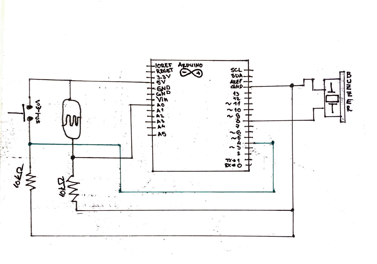
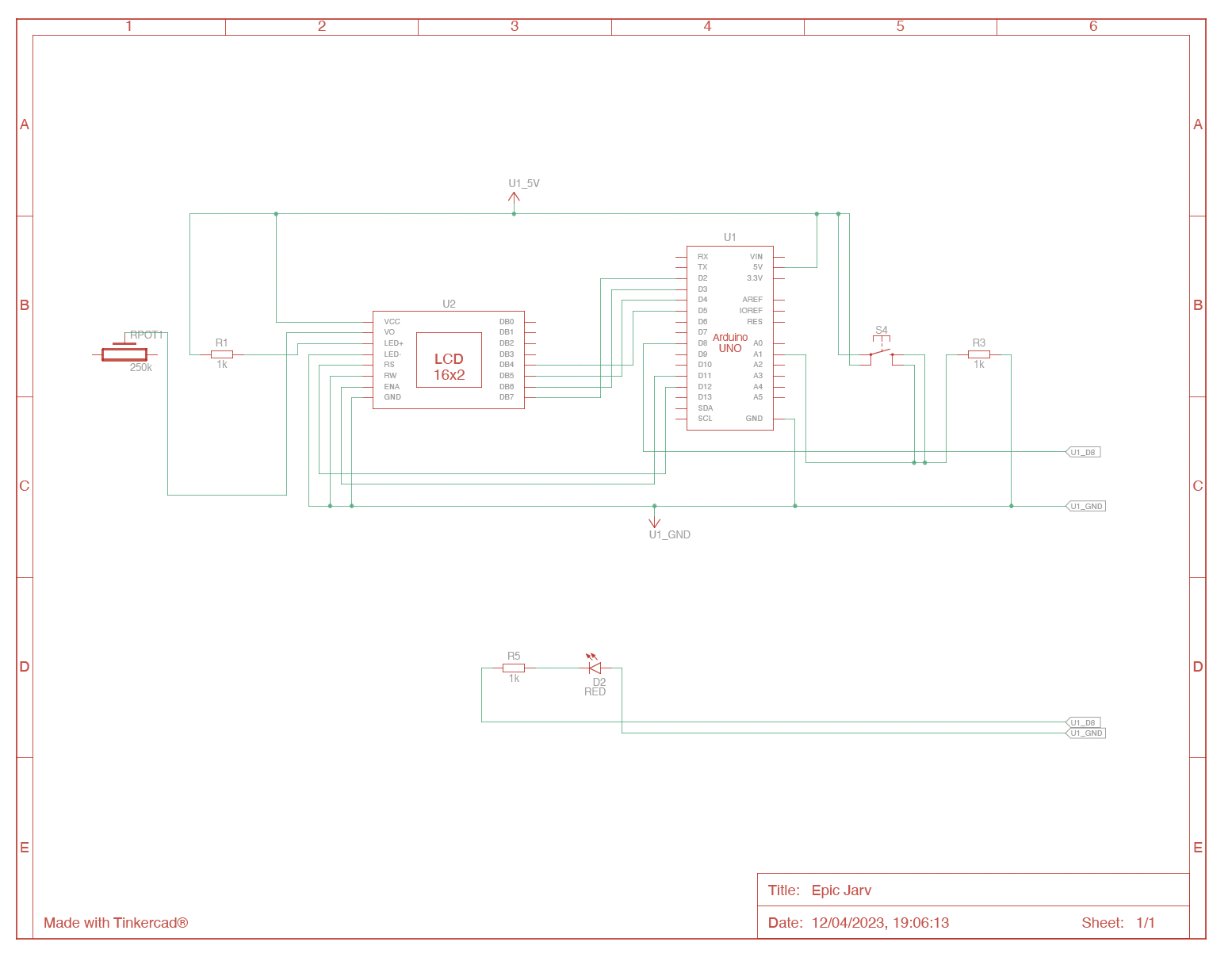
Using serial communication between p5.JS and arduino, I was able to send distance values to p5.js to control Naruto in the game. The Arduino code is responsible for reading sensor data, processing it, and sending it to the p5.js program. Here’s the Arduino Code:

// defines pins numbers
const int trigPin = 9;
const int echoPin = 10;
// const int ledPin = 3;
// int duty = 10;
// defines variables
long duration;
int distance;
void setup() {
  pinMode(trigPin, OUTPUT); // Sets the trigPin as an Output
  // pinMode(ledPin, OUTPUT); // Sets the trigPin as an Output
  pinMode(echoPin, INPUT); // Sets the echoPin as an Input
  Serial.begin(9600); // Starts the serial communication
}
void loop() {
  // Clears the trigPin
  digitalWrite(trigPin, LOW);
  delayMicroseconds(2);
  // Sets the trigPin on HIGH state for 10 micro seconds
  digitalWrite(trigPin, HIGH);
  delayMicroseconds(10);
  digitalWrite(trigPin, LOW);
  // Reads the echoPin, returns the sound wave travel time in microseconds
  
  duration = pulseIn(echoPin, HIGH);
  // Calculating the distance
  distance = duration * 0.034 / 2;
  // Prints the distance on the Serial Monitor * 0.034 / 2
  // analogWrite(ledPin, duty);
  Serial.println(distance*4);
  delay(150);
}


P5.JS:

The p5.js code handles the game’s main logic and rendering. It includes functions to load images, control the movement of the landscape, manage game states (main screen, gameplay, game over), and handle collisions between objects. The code uses the sprite concept to represent Naruto, obstacles, and other elements in the game. It also includes functions for drawing the main screen and game over screen and the mousePressed function attached to clicking on Play before the start and to restart the game each time it’s over. I’ll be submitting the project below so you can all take a look over the p5.js code.

Communication between Arduino and p5.js

The communication between Arduino and p5.js is established through a serial connection. The p5.js program reads the distance values sent by the Arduino and uses them to control Naruto’s vertical position. The Arduino continuously sends distance data, which is received by the p5.js program. This communication allows the player to control Naruto’s movement in real-time.


Cool Things in the game:

Here are some of game prospects that I am most proud of:

Parallax Landscape: The game features a visually appealing parallax landscape, where the background scrolls at a slower speed than the foreground, creating depth and immersion.

Sprite Animation: The use of sprite animation brings Naruto and other elements to life, enhancing the game’s visual experience.

Intuitive Controls: The game utilizes an Arduino device to control Naruto’s movement, providing a unique and engaging gameplay experience.

Here’s the p5.js code for this project:

Future Improvement

Game Difficulty: Implementing adjustable difficulty levels or introducing new obstacles or power-ups could enhance the game’s replay value.

Audio: Adding sound effects and background music would contribute to the game’s overall atmosphere.

Changing the values received from arduino when communicating data with it: As the sensor values increase from down to up, the movement of Naruto on the screen is opposite the way it should be. I would like to fix this feature in future.


User Testing:

Here’s the video of one of my friends trying to play the game.


I think the controls were not really difficult for the players to understand. My friend was able to figure out the controls on his own and was able to score good score in his 3rd try.

Again, the only problem here is that the movement of Naruto is opposite than the user movement of his/her hands. For example, when going up with the sensor, Naruto goes down. This is one of the main issue I faced and couldn’t find a way to fix it. Hopefully, when I make changes to this project in Future, I’ll be able to figure out the solution for this problem.


Final Proposal

 Idea/Concept:

For the final project, I have decided to develop a simple game using p5.js and Arduino Uno. The game is the same as the popular Dinosaur Game by Google. The game involves controlling the dinosaur character by making it jump over obstacles using a button on the Arduino board. To make the game more interesting, the player can also challenge the Arduino board, which will be controlling the button using a servo motor with a tiny hook attached at the end of the motor to press the button.

How to Play Google Chrome Dinosaur Game both Online and Offline -  Studytonight

Serial Communication (Arduino & P5js):

Arduino:

The Arduino board is responsible for controlling the servo motor and reading the status of the game mode selection button and the challenge button. The board communicates with the p5.js game over serial communication.

P5.js:

The p5.js game is responsible for rendering the graphics of the game and communicating with the Arduino board over serial communication. The game receives the status of the dinosaur’s jump button and sends the status of the challenge mode selection button.

Game Modes:

Single player: the user controls the dinosaur jump with a button attached to the Arduino board.

Challenge mode: the user competes against the Arduino board, which controls the dinosaur’s jump using a servo motor. If the user selects the challenge mode, the Arduino board will play first by pressing the dinosaur jump button using the servo motor. The user’s turn starts after the Arduino’s turn. During the user’s turn, the user can press the button attached to the Arduino board to make the dinosaur jump. The user’s score is displayed on the screen, and the game ends when the user fails to jump over an obstacle.

Problems (Training Arduino to play the game):

There’s only one possible problem that I might face while doing this project and that is challenge mode. For the challenge mode to work, I have to train Arduino to turn the servo motor whenever there’s an obstacle. However, I looked on the internet and I think I will be able to train using a simple algorithm on p5.js. The breakdown of the algorithm is as follows:

  1. Use the p5.js pixels array to get the color of the pixels representing the obstacles on the screen.
  2. Check if there are any obstacles present by looking for a specific color in the pixels array.
  3. If an obstacle is present, move the servo motor to press the dinosaur jump button.
  4. Wait for a short time to allow the dinosaur to jump over the obstacle.
  5. Release the servo motor to allow it to return to its initial position.

Hopefully, this will fix the issue. It might require a lot of testing for the motor to match the time of the obstacles appearing on the screen.

Week 10: Arduino-P5 exercises (Youssef-Arslan)

Exercise 1: Make something that uses only one sensor on Arduino and makes the ellipse in p5 move on the horizontal axis, in the middle of the screen, and nothing on Arduino is controlled by p5.

P5 link: https://editor.p5js.org/Arslan108/sketches/DVc3r1-YY Arduino script:

// defines pins numbers
const int trigPin = 9;
const int echoPin = 10;
// const int ledPin = 3;
// int duty = 10;
// defines variables
long duration;
int distance;
void setup() {
  pinMode(trigPin, OUTPUT); // Sets the trigPin as an Output
  // pinMode(ledPin, OUTPUT); // Sets the trigPin as an Output
  pinMode(echoPin, INPUT); // Sets the echoPin as an Input
  Serial.begin(9600); // Starts the serial communication
}
void loop() {
  // Clears the trigPin
  digitalWrite(trigPin, LOW);
  delayMicroseconds(2);
  // Sets the trigPin on HIGH state for 10 micro seconds
  digitalWrite(trigPin, HIGH);
  delayMicroseconds(10);
  digitalWrite(trigPin, LOW);
  // Reads the echoPin, returns the sound wave travel time in microseconds
  
  duration = pulseIn(echoPin, HIGH);
  // Calculating the distance
  distance = duration * 0.034 / 2;
  // Prints the distance on the Serial Monitor * 0.034 / 2
  // analogWrite(ledPin, duty);
  Serial.println(distance);
  delay(150);
}

The Ball class defines the properties and methods for the ball, including its position, velocity, and radius. The update() method updates the ball’s horizontal position and velocity according to the gravity, bounce factor, and the sensor value that is taken from the ultrasonic distance sensor. The show() method is responsible for displaying the ball on the canvas.

Exercise2: Make something that controls the LED brightness from p5

P5 link: https://editor.p5js.org/Arslan108/sketches/rSn6NmdHy. Arduino script:

int ledPin = 3;


void setup() {
  pinMode(ledPin, OUTPUT);
  Serial.begin(9600);
  // put your setup code here, to run once:
  

}

void loop() {
  while (Serial.available()) {
    // digitalWrite(LED_BUILTIN, HIGH); // led on while receiving data

    int duty = Serial.parseInt();
    if (Serial.read() == '\n') {
      analogWrite(ledPin, duty);
    }
 

}
}

The code allows the control the intensity of the light emitted by the LED depending on the Y coordinate of the mouse. The higher the Y-coordinate is the brighter the LED is.

Exercise 3: Make something that controls the LED brightness from p5.

P5 link: https://editor.p5js.org/Arslan108/sketches/yhLl1hYsD. Arduino script:

// defines pins numbers
const int trigPin = 9;
const int echoPin = 10;
const int ledPin = 4;
// int duty = 10;
// defines variables
long duration;
int distance;
void setup() {
  pinMode(trigPin, OUTPUT); // Sets the trigPin as an Output
  pinMode(ledPin, OUTPUT); // Sets the trigPin as an Output
  pinMode(echoPin, INPUT); // Sets the echoPin as an Input
  Serial.begin(9600); // Starts the serial communication
}
void loop() {
  // Clears the trigPin
  digitalWrite(trigPin, LOW);
  delayMicroseconds(2);
  // Sets the trigPin on HIGH state for 10 micro seconds
  digitalWrite(trigPin, HIGH);
  delayMicroseconds(10);
  digitalWrite(trigPin, LOW);
  // Reads the echoPin, returns the sound wave travel time in microseconds
  
  duration = pulseIn(echoPin, HIGH);
  // Calculating the distance
  distance = duration * 0.034 / 2;
  // Prints the distance on the Serial Monitor * 0.034 / 2
  int duty = Serial.parseInt();
    if (Serial.read() == '\n') {
      digitalWrite(ledPin, duty);
    }
  Serial.println(distance);
  delay(150);
  // digitalWrite(ledPin, low);
}

We have kept the code form exercise 1 but we have added the lines that send the light up order to the LED, every time the ellipse get in contact with the right or the left borders of the canvas.

let sendToArduino = light + "\n";
writeSerial(sendToArduino);
light = 0;


Week 10: Light Theremin (Arslan & Stefan)

Concept:

For this assignment, we wanted to create a version “Theremin” that will be linked with the light sensor and will produce sound based on the light intensity received by the sensor on Arduino board. Additionally, we’ll add the switch to this Light Theremin to change the frequency of the sound and to play different sounds using the light sensor. The frequency only changes while the button is pressed, we did this to change tune while playing the theremin which makes it easier for the user to play different tone from both frequencies. In short, the analog in takes values from the light sensor and these values are converted within a certain limit to be played through the buzzer. When the button is pressed, the limit of these values changes and thus giving us the tone of higher frequency.

SCHEMATIC:
Video:

Code:

// create variable to hold sensor value
int sensorValue;
// UNO's analog read sensors use "analog to digital converter" (ADC),
// which means it divides the reading coming from the sensor (0 to 5 volts) into 1024 equal steps.
// Thus, the reading from our photoresistor could range from 0 to 1023,
// however it is unlikely to use the full range so we will calibrate it.
// For now, create variables to hold the high and low value for our photoresistor range, 
// make them the opposite of the max/min values and we will calibrate them down.
int sensorLow = 1023;
int sensorHigh = 0;
// set the LED pin, 13 is the built in LED
const int ledPin = 13;
int switchFreq = 4;
int switchVal;


void setup() {
  
  
  pinMode(ledPin, OUTPUT);
  pinMode(switchFreq, INPUT);
  
  digitalWrite(ledPin, HIGH);
  
  delay(500);
  
  digitalWrite(ledPin, LOW);
  delay(500);
  digitalWrite(ledPin, HIGH);
  delay(500);  
  digitalWrite(ledPin, LOW);
  delay(500);
  digitalWrite(ledPin, HIGH);

  // after it blinks for 2 seconds, its time to calibrate the photoresistor readings
  // create a loop with while() that lasts for 5000 ms to calibrate the light sensor according the setting, 
  while (millis() < 5000) {
    // use analogRead() to get a reading from the photoresistor,
    sensorValue = analogRead(A0);
    // create two conditions using if() to calibrate the max and min sensor values,
    // raise the sensorHigh if the current reading is higher:
    if (sensorValue > sensorHigh) {
      sensorHigh = sensorValue;
    }
    // lower the sensorLow if the current reading is lower:
    if (sensorValue < sensorLow) {
      sensorLow = sensorValue;
    } 
  }
  
  // turn the LED off, calibration is done!
  digitalWrite(ledPin, LOW); 
}


void loop() {
  //read the input from A0 and store it in a variable
  sensorValue = analogRead(A0);
  switchVal = digitalRead(switchFreq);

  // map(currentValue, oldRange1, oldRange2, newRange1, newRange2)
  // I reverse their order (high, low) so that shading the photoresister will cause a higher tone.
  // the new range is the range of Hz to use to produce sound, which for UNO can be from 31 to 65535 Hz.
  // I set it from 0 to 300, which is a more normal sound range and if a button is pressed I change the values between 500 to 1000
  // since we start at 0, full light will make no tone, full shade will make the highest tone.
  if (switchVal == HIGH){
  int pitch = map(sensorValue, sensorHigh, sensorLow, 500, 1000);
  tone(8, pitch, 10);
  }
  else{
    int pitch = map(sensorValue, sensorHigh, sensorLow, 0, 300);
    tone(8, pitch, 10);
  }
  // use the tone function to create sound in the piezo, 
  // tone(pin#, value, milliseconds)
  

  // add a delay to make the current tone sustained for a few ms to adjust the quality of the tone
  delay(15);
}


Future improvements:

For future, we want to use more than 2 limits of frequencies and we want to add instruments that could be switched using the button. After completing this project, we realised that playing sound using the light sensor is easier than any other sensor since it only requires basic movements of hands to block the light or allow the light to the sensor. Thus, in future, we’d like to add more instruments like electric guitar frequencies and allow users to switch between these instruments using the switch buttons.

Week 9: NEVER HAVE I EVER with Arduino

Concept:

For this assignment, I wanted to create a basic version of “Never have I ever” game. The rules of this game are simple, usually there’s a narrator who says something and if any of the player has done that they say, “I have”. I wanted to create this game on Arduino using the LCD screen, the switch button, and the red led. Instead of the narrator, I wanted to display a text on the lcd screen and if the player has done that thing, they press the switch that will light up the led to show the other players. In short, pressing the button is equivalent to saying, “I HAVE” in the real game. For this reason, I went on internet and tried to understand the working of the LCD screen that comes with Arduino UNO and linked it with the switch to control the texts that were displayed on the screen. I was able to create a basic version of this game with just one prompt as I was struggling to reset the cursor placement on the screen. There’s a welcome message that is displayed and is shown until the user presses the switch. Then the first prompt is there, and the user can press the switch to indicate that he/she has done that.

Schematic:
COde:


// include the library code:
#include <LiquidCrystal.h>

// initialize the library by associating any needed LCD interface pin
// with the arduino pin number it is connected to

const int rs = 12, en = 11, d4 = 5, d5 = 4, d6 = 3, d7 = 2;
int redLEDPin = 8;
int trueSwitch = A1;

String welcome = "Welcome Players! The rules of the game are simple: Press RED button if you have! Press RED button to Proceed";
int leng = welcome.length();
char myText[50] = "Never have I ever got on the wrong train or bus?";
bool StartGame = false;
int promptcount = 0;

LiquidCrystal lcd(rs, en, d4, d5, d6, d7);

void setup() {

  // set up the LCD's number of columns and rows:
  lcd.begin(16, 1);
  pinMode(redLEDPin, OUTPUT);
  pinMode(trueSwitch, INPUT);
}

void loop() {

  // set the cursor to (0,0):


  lcd.setCursor(0, 0);

  // print from 0 to 9:
  // lcd.autoscroll();
  for (int thisChar = 0; thisChar < leng; thisChar++) {
    int truePos = digitalRead(trueSwitch);
    if (truePos == HIGH){
        digitalWrite(redLEDPin, HIGH);
        delay(600);
        StartGame = true; 
        digitalWrite(redLEDPin, LOW);
        break;  
      } 

    lcd.print(welcome[thisChar]);

    if (thisChar == 15){
      lcd.autoscroll();
    }

    delay(200);

  }
  lcd.clear();
  lcd.noAutoscroll();
  delay(2000);


  // set the cursor to (16,1):

  
  // clear screen for the next loop:

  while (StartGame){
    
 
    lcd.clear();

    lcd.setCursor(0, 0);

    // print from 0 to 9:
    // lcd.autoscroll();
    for (int thisChar = 0; thisChar < 50; thisChar++) {
      int truePos = digitalRead(trueSwitch);
      if (truePos == HIGH){
        digitalWrite(redLEDPin, HIGH);
        promptcount++;
        delay(300);   
      } 
      lcd.print(myText[thisChar]);
      if (thisChar == 15){
        lcd.autoscroll();
      }

      delay(300);

      digitalWrite(redLEDPin, LOW);

    }

    // set the cursor to (16,1):

  
    // clear screen for the next loop:

  
    lcd.noAutoscroll();
    lcd.clear();
  }
}


Video:

Future Improvements:

As I mentioned earlier, I couldn’t add more than one prompt to this project. For future, I would like to create an array of different prompts that switches as soon as the user presses the switch. Moreover, to make the game more interesting I would like to add more switches with more LEDs to involve more than one player in the game.

Unusual Switch (Clipping)

Concept:
For this assignment, I wanted to create a simple switch using something in my room. I decided to do it with the laundry clip. I had to attach the wires to both ends of the clips so that the circuit is complete as soon as the clip is closed. I tied a thread on both ends of the clip and placed wires in it. Now, if the clip is closed the light is on, otherwise, if it’s open, the light will turn off.

Here’s the video:

IMG_7699 (1)

Future Improvements:

I was able to achieve what I wanted from this assignment. However, in the future, I would like to use a conductor between the clips so that I can increase the distance between the Arduino board and the switch. Moreover, I would like to use the switch for some games or interaction between Arduino and the computer.

Mid-Term Project: Traffic Racer

Assignment 3: OOP DESIGN

Concept & Inspiration:

For this assignment, I wanted to create the “Metatron’s Cube,” a sacred geometrical figure that has been used in various spiritual and mystical traditions throughout history. The figure is named after the biblical figure Metatron, who is said to have acted as a mediator between God and humanity. I wanted to use p5.Js to combine digital art with ancient spiritual wisdom. Here’s how this figure looks like:
What Is a Metatron’s Cube — and Why Is It Significant? - Symbol Sage

I didn’t expect that this figure would be really difficult to draw in p5.js. However, for the sake of this assignment and using the ideas of the object-oriented programming, I was able to draw set of nodes, represented as small circles, that move in circular orbits around the center of the canvas. Lines are drawn between nodes that are close enough together. The positions of the nodes are updated based on their angle around the center, which changes over time. Moreover, it allows user to interact by adding or removing nodes with mouse clicks or the backspace key, respectively. The current number of nodes and lines are displayed on the canvas for reference. I was able to draw some thing similar to the “Metatron’s Cube”.  Here’s how the final version look like:

Future Improvements:

Although, I couldn’t really achieve what I wanted to, this project gave me some idea how I can create an actual metatron’s cube using p5.js. So, obviously in future I’d like to create the actual figure. Moreover, I’d like to add meditating music in the background. I’d also like to improve some of the visual aspects of my work such as adding more colors and some objects in the background. Lastly, I think digital art is all about interactions and would like to add more interactivity features such as allowing users to control the speed or direction of the nodes and lines, or to change the color scheme in real-time using user inputs.


Assignment 2: WEBGL 3D Art

Concept:

Initially, my concept for the assignment was fairly simple, I wanted to create a mandala by drawing ellipses and lines using the sin and cos function. However, when I got into the process of learning how to use the sin and cos function, I found number of tutorials where these functions were being used to draw 3d shapes. I started with the basic drawings in the webGL renderer and then moved on to making 3d spheres using sin and cos function combined with the beginShape and endShape functions. Once I was able to make a sphere, I tried rotating the accidentally discovered that by keeping the rotation at a certain degree I was able to draw a mandala on the canvas. Hence, I kept the code and added some interactivity to my sketch.

Code and Interactivity:

The code draws two spheres in 3D  using WebGL. In the setup() function , iI changed the canvas with a WEBGL renderer and sets the frame rate to 10.

User can control the camera angle of viewing this shape by simultaneously pressing mouse and moving around in the canvas which is controlled using the orbitControl function. Then I run a loop that generates a random stroke color for each iteration. I rotated the canvas along the X, Y, and Z axes by 90 degrees to achieve the mandala.

Furthermore, I run nested for loops that generates the spheres using the sphere_draw function. This function calculates the position of a vertex on the sphere using spherical coordinates, and adds the vertex to the shape. The spheres are drawn by connecting these vertices. The radius of the second sphere depends on the mouse X position, to create an interactive effect.

This code creates an interactive 3D visualization of two spheres, with the user able to control the camera and view the spheres from different angles and of different radius. Here’s the final sketch:

Future Improvements:

For the sake of more visualisation and Interactivity, I hope to add user controls on the side for adding more spheres, changing color of each sphere and resizing. Moreover, I discovered that I could create mandala using two spheres accidentally which is why I want to work with other 3d shapes to end up in similar accidents.


Assignment 1: Self Portrait

Overview:

For this assignment, we were asked to draw a self portrait using the basic functions built into p5.JS. I started by drawing a rough sketch of what I wanted my self portrait to look like. For the self portrait, I tried to highlight the main features of my face. I think my spectacles are one of the very important feature of my face so I decided to add these to the portrait. Furthermore, while coding and looking at the examples that were provided to us, I decided to add some interactive features to the portrait. Overall, the assignment was really fun and helped me in understanding some of the key concepts of p5.JS.

Concept & Process:

The concept for my self portrait was fairly simple. I wanted to make sure that I add all the key features of my face and give it a animated look. I tried adding curly hair but it turned out to be really difficult and the results that I got after that weren’t really satisfying so I just went ahead with normal hair. I just used arc over my head to make it look like hair. As I mentioned earlier, spectacles were really important to me so I spent fair amount of time fixing them around the eyes. I used arc function and line to make it look more realistic. Moving on, for the nose and the lips, I used arc to make both of these. For the ears, I just rotated the arc and added those arcs on the both sides of my face. Furthermore, I added a neck and shirt using the rect function. I added the arms on the both sides by increasing the stroke weight and drawing lines next to the shirt. This turned out to be really realistic and allowed me to get the look that I wanted from this self-portrait.

Interactivity:

Inspired by the examples, I decided to add some interactive features to the portrait. For the background, whenever the mouse is moved around the canvas, ellipses are drawn of different colors. This required to run a for loop within the draw function and generate random values between 0 and 255 for r,g and b to later use them in the fill function. Furthermore, similar to the of “Koala portrait” example, I decided to make the eyes move in the same direction where the pointer goes on the canvas. This was fairly simple and all that required was to multiply the coordinates of the pointer  on the canvas with a very small constant  and add it to the coordinates of the ellipse that I had drawn for the pupils. This allowed me keep the pupil within the eyes and add this simple interactivity. Lastly, when the mouse key is pressed, the color of the shades is changed to random colors to create a cool effect. Again, I generated three random values for the r g and b using a for loop and the random function of p5.js to use these values in the fill function.

Future Improvements:

In future, I want to learn change this portrait from an animated one to a more realistic one. I hope to learn how to make curly hair and add it to this portrait. Furthermore, I’d like to add better and more artistic animations for the background. I would love to design better nose and ears using the points or any other function that allows me give them a more realistic touch. I hope to learn these skills and implement them on this portrait.Here’s how the final portrait look like: