Cupid
The Concept:
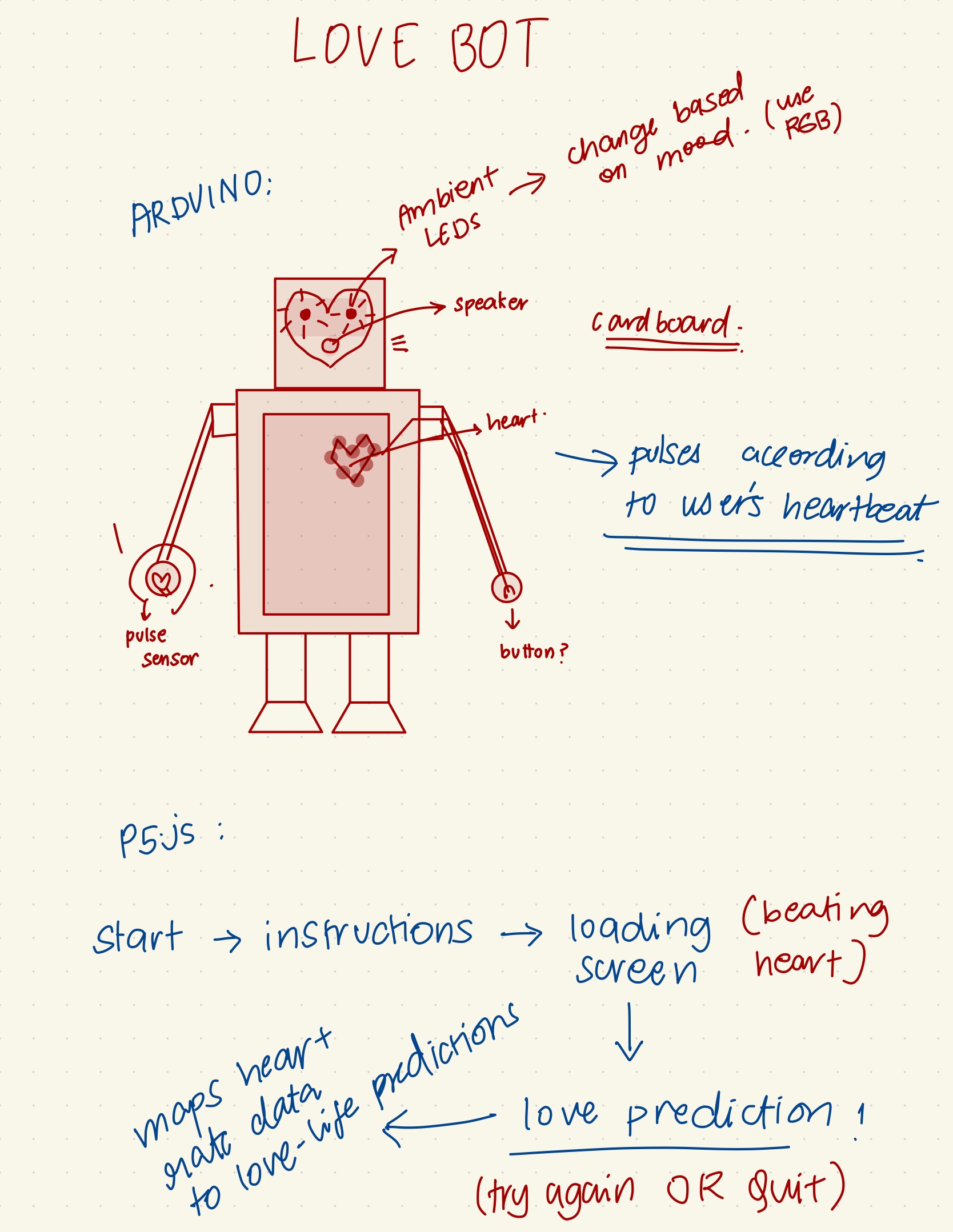
Cupid first took root with a simple LED heart. From the very start, I knew I wanted to incorporate this element – a beating, glowing heart that could serve as the centrepiece for an interactive experience. However, I hadn’t quite decided how to elevate it beyond just this into something more profound and immersive.
And then 💡! – what if this heart could be linked to the user’s own pulse? By integrating a pulse sensor, I could make each person’s unique heartbeat bring the LED heart to life, creating a personalised connection.
This sparked the concept for Cupid – an interactive cardboard robot that detects your heartbeat through pulse sensing, uses it to animate a glowing LED heart in its chest, and even generates humorous, randomly selected (chatGPT generated 🤭 ) “love predictions” based on your heart rate variability data.
The goal was to craft an experience that the love child of playful and whimsy. By encouraging users to form a “heart-to-heart connection” with this quirky robot, the interaction taps into something innately human – our capacity for creating emotional bonds and embracing moments of lighthearted joy.
Brainstorming:
The Process:
The Heart:
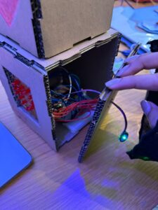
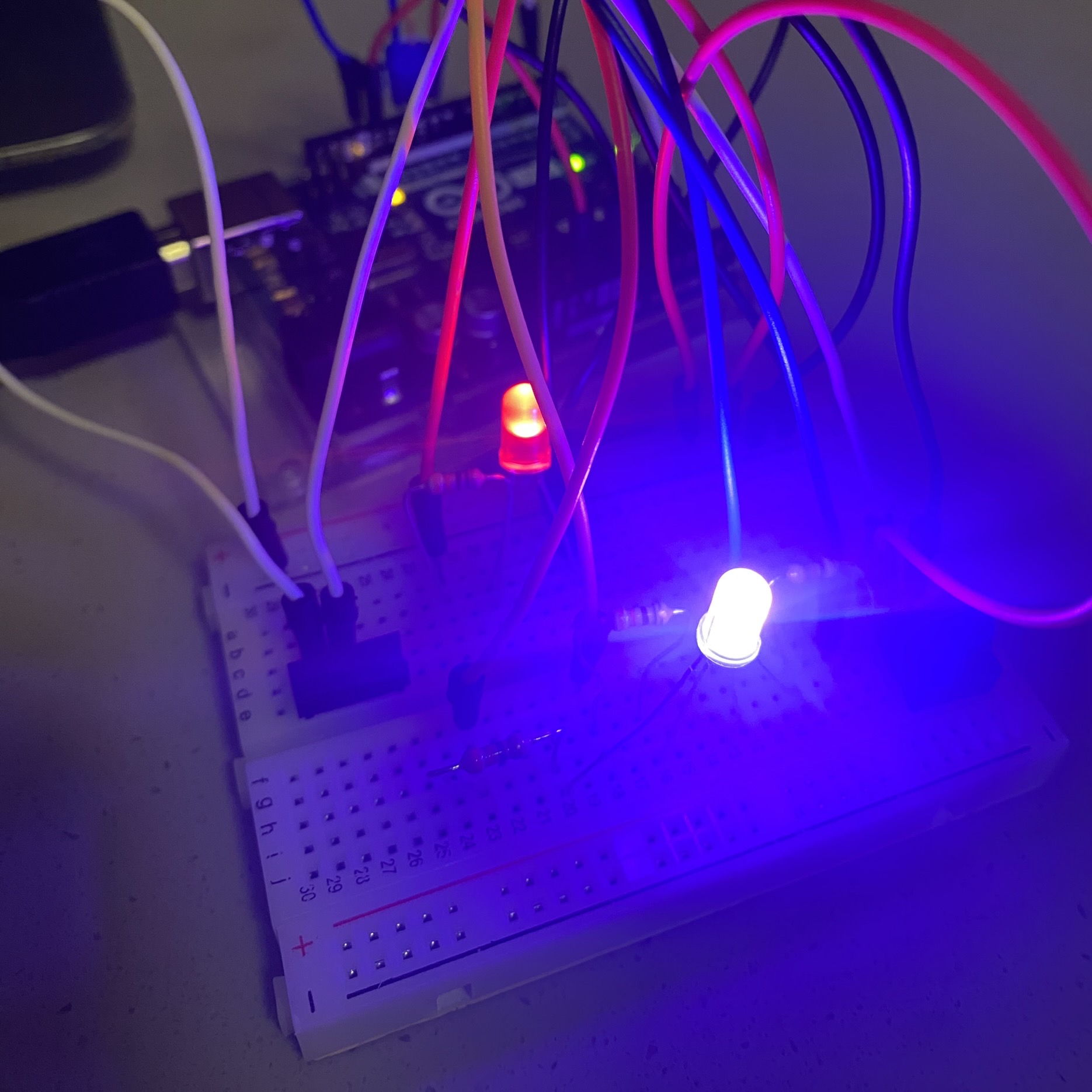
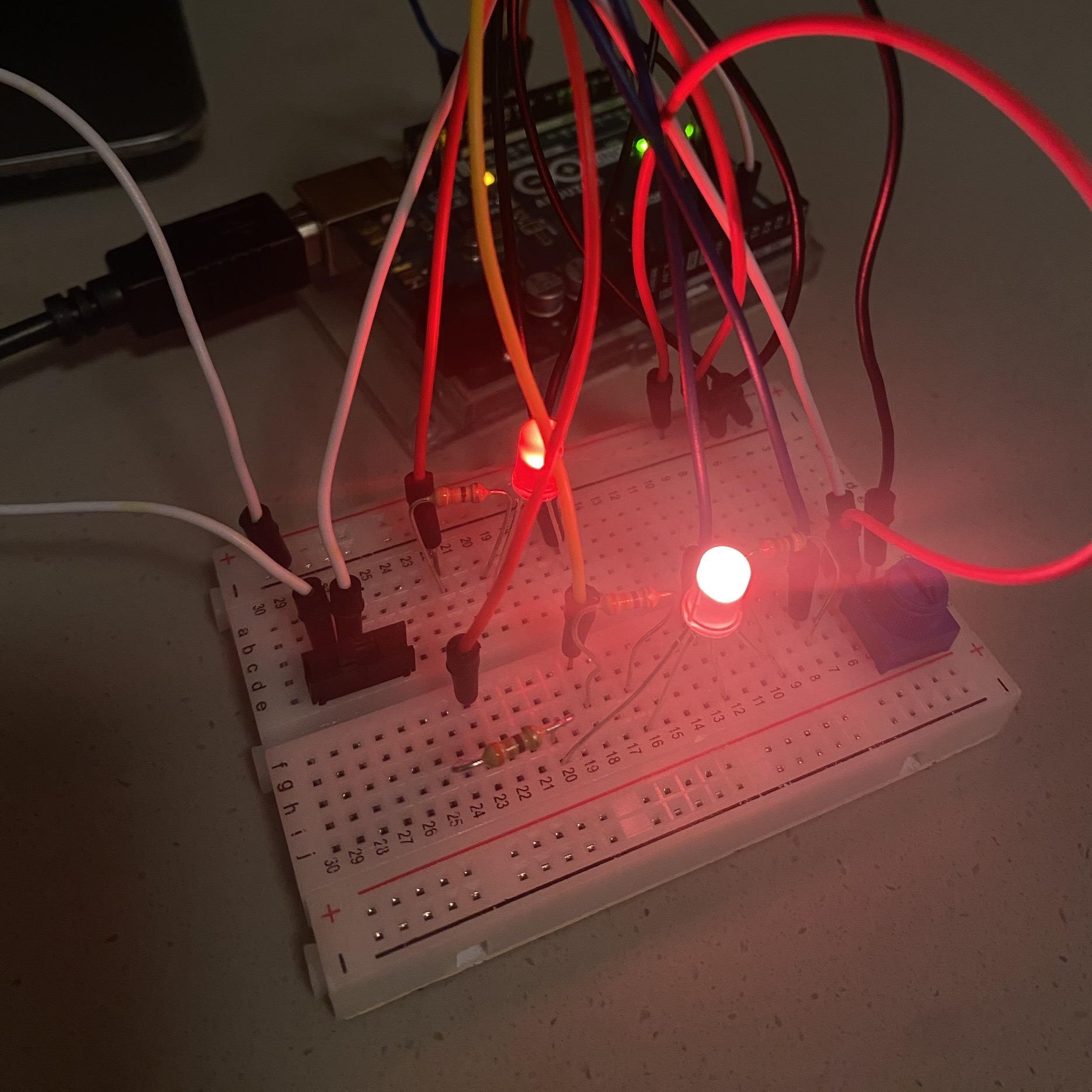
Building the pulsing LED heart for Cupid was quite a challenge. The biggest issue was that I needed 16 LEDs, but the Arduino only had 13 digital pins available. To work around this, I had to get creative and connect the LEDs in pairs using soldering.
For each pair, I soldered the negative leg of one LED to the positive leg of the other LED. Then, I soldered the negative leg of the second LED to a 330-ohm resistor to control the current. After doing this for all 8 pairs, I soldered a single wire to the positive end of each pair.
Finally, I bundled all the negative resistor legs together and connected them to a single ground wire. This way, I could control the 16 LEDs using just 8 digital pins from the Arduino.
While this wiring setup took some careful soldering work (and far more time than I’d like to admit), it allowed me to create the synchronised pulsing heart effect that became the centrepiece of Cupid. Tinkering with the soldering iron, meticulously joining the wires and components, I found an unexpected sense of satisfaction and joy in the hands-on process. It made me realise how much I enjoy working with tangible tools.
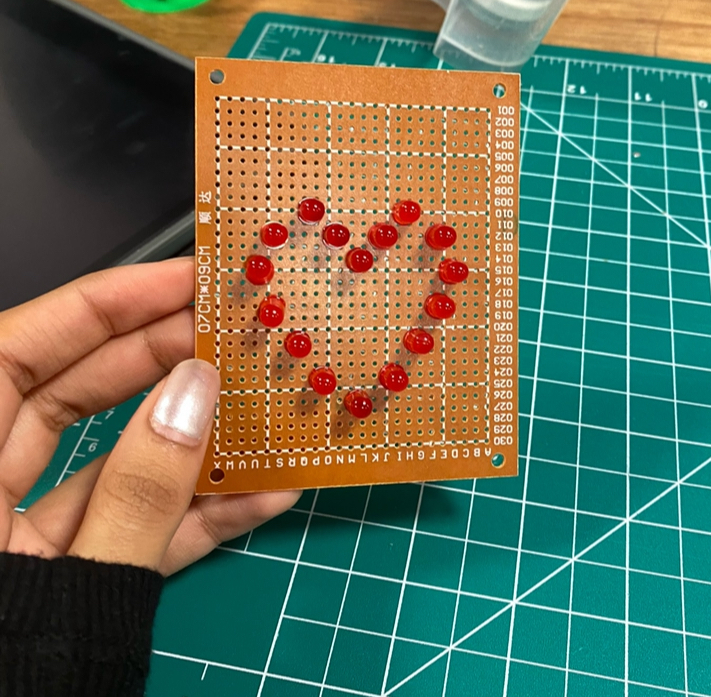
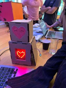
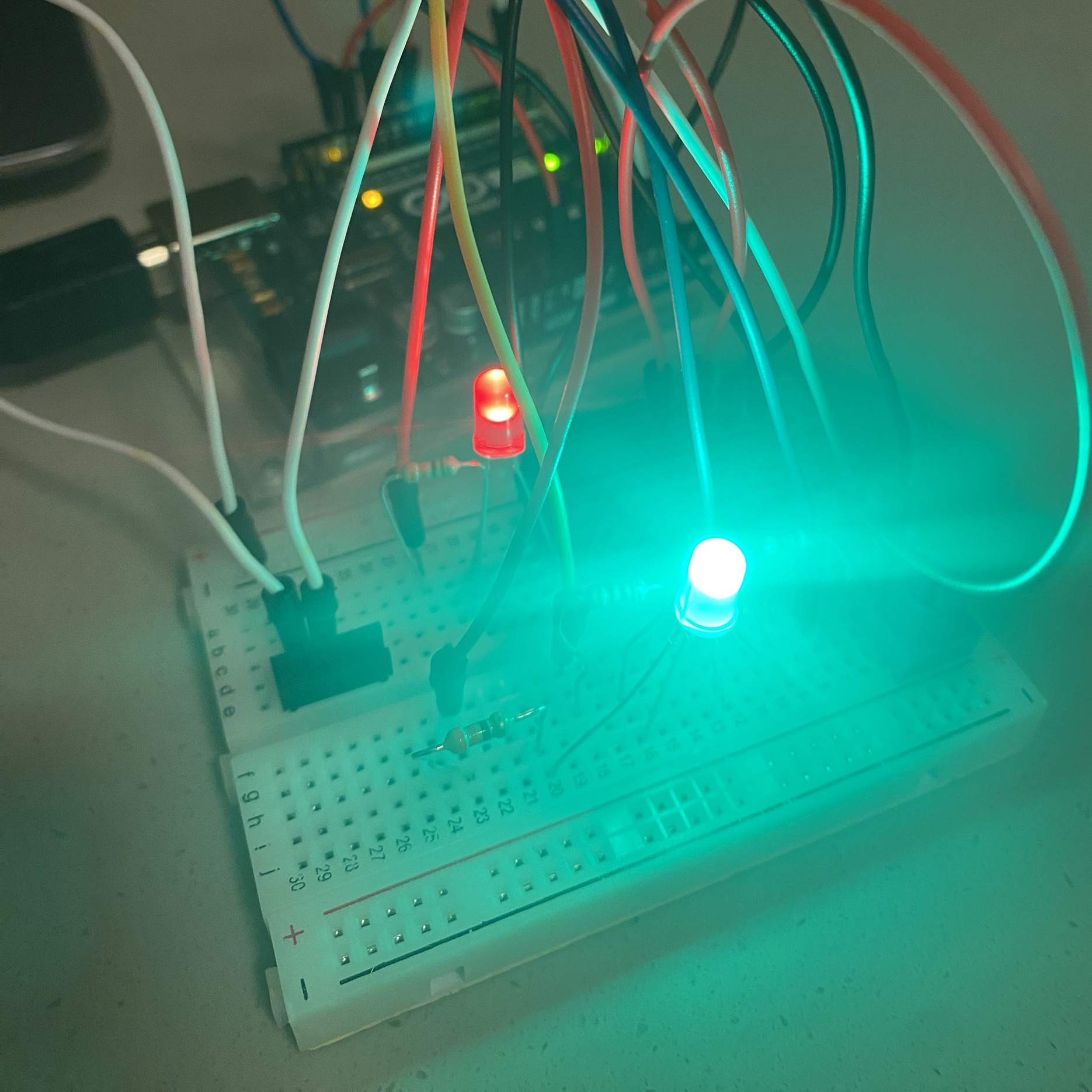
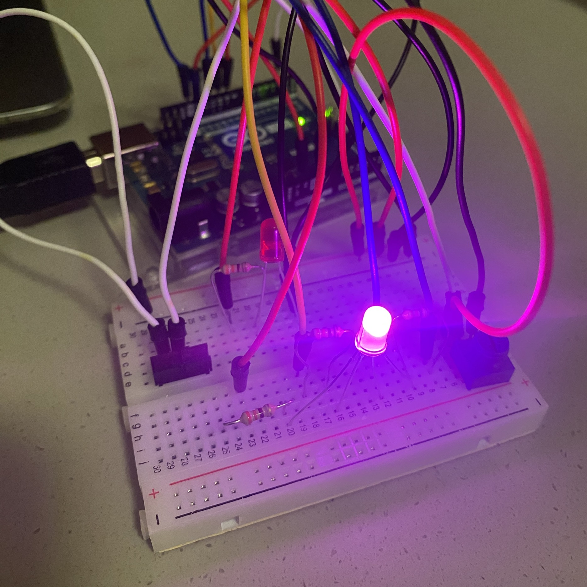
Cupid in her early stages 😋
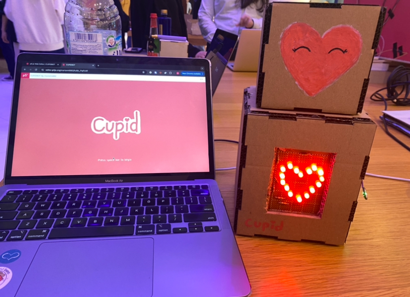
The P5 Sketch:
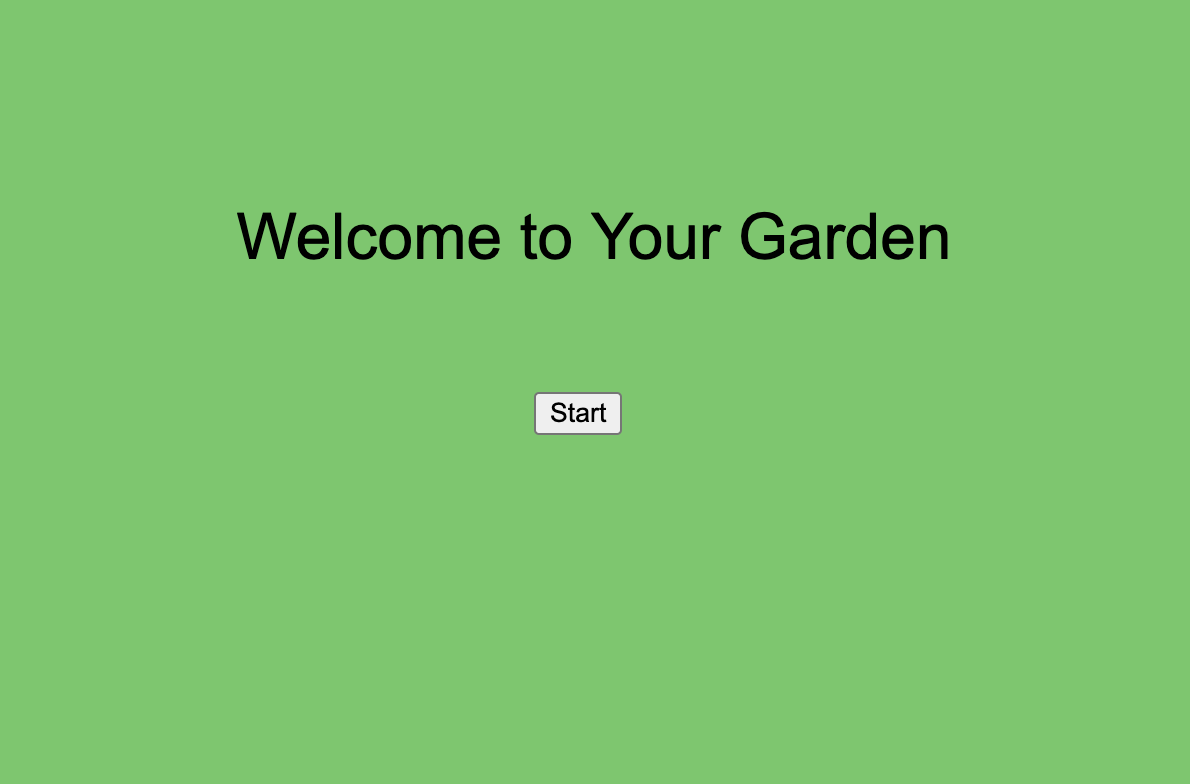
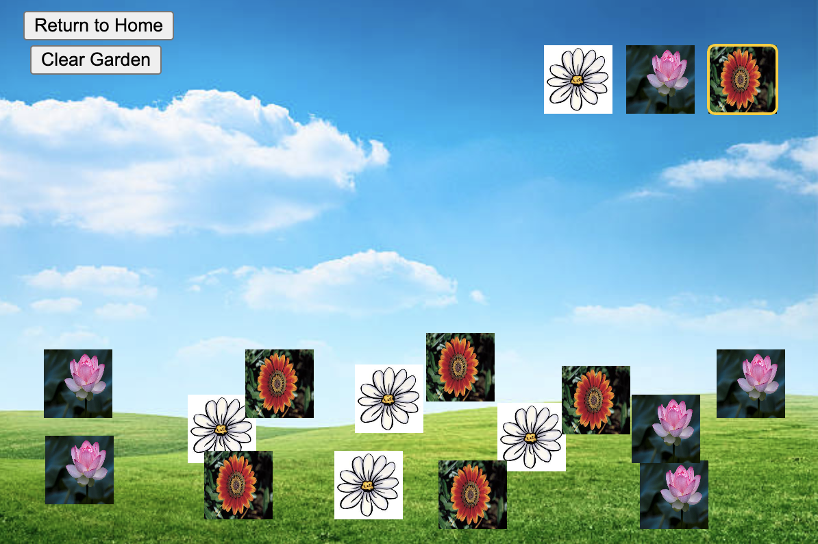
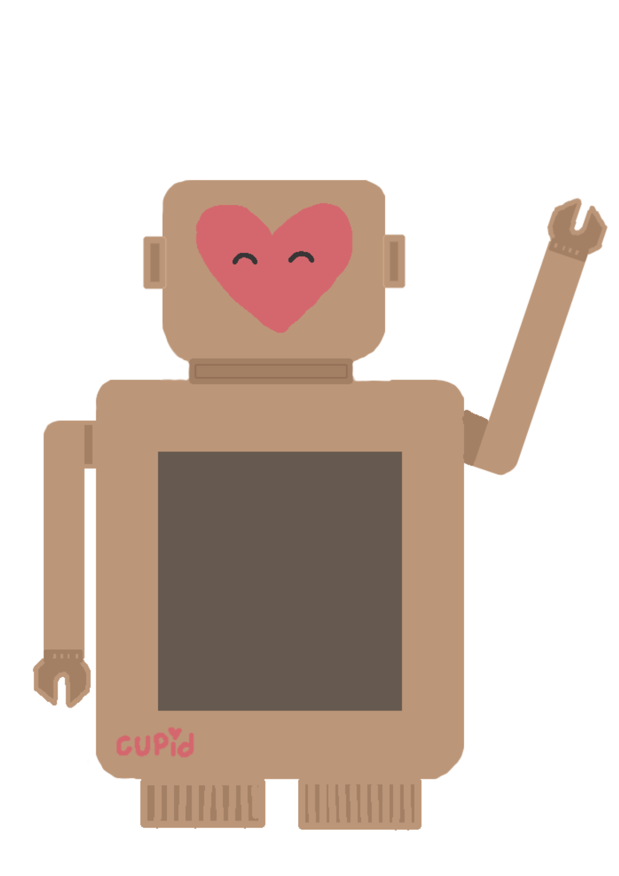
After the intricate work of building Cupid’s LED heart, creating the p5.js sketch felt relatively simple. I took a hands-on approach by hand-drawing the title page illustration. Then I drew Cupid’s adorable (i’m biased) robot body. I wanted to infuse the character with warmth and likability. While the p5.js coding was more technical, the artistic process of drawing Cupid made this phase of the project very enjoyable and satisfying.

Now it was time to bring her to life through code. The p5.js sketch served as the digital heart (hehe) of this project. Here’s a breakdown of some key elements of the code:
- Heart Animation: The pulsing LED heart effect was achieved by gradually reducing the size of the heart shape (
heartSize) over time. This created a lifelike pulsation that synced with the user’s heartbeat.
if (state === 1 && heartSize > 50) {
  heartSize *= 0.97;  // Gradually reduce heart size to simulate the beat
}
- State-Based Interaction: Cupid’s interaction was divided into different states (0, 1, and 2) to control the flow of the experience. These states determined what was displayed on the screen and how Cupid responded to user input.
switch (state) {
  case 0:
    imageMode(CENTER);
    image(text1, width / 2, height / 2);
    fill("#FED4D6");
    textSize(30);
    text("Press space bar to begin", width / 2, height - 100);
    break;
  case 1:
    imageMode(CENTER);
    image(cupidbot, width / 2, height / 2);
    drawHeart();
    fill("#FED4D6");
    textSize(40);
    if (timeHeartbeatDetected && millis() - timeHeartbeatDetected < 10000) {
      text("making heart to heart connection", width / 2, height / 10);
    } else if (timeHeartbeatDetected) {
      text("connection made. press enter to know your love prediction", width / 2, height / 10);
      displayPredictionText = true;  // Enable showing the prediction prompt
    } else {
      text("hold my hand to make a connection", width / 2, height / 10);
    }
    break;
  case 2:
    fill("#FED4D6");
    textSize(35);
    text(prediction, width / 2, height / 2);
    if (displayPredictionText) {
      noStroke();
      fill("#FED4D6");
      rect(width / 2 - 100, height - 150, 200, 50);  // Draw quit button
      fill("#D76770");
      textSize(30);
      text("quit", width / 2, height - 125);
    }
    break;
}
P5 Sketch:
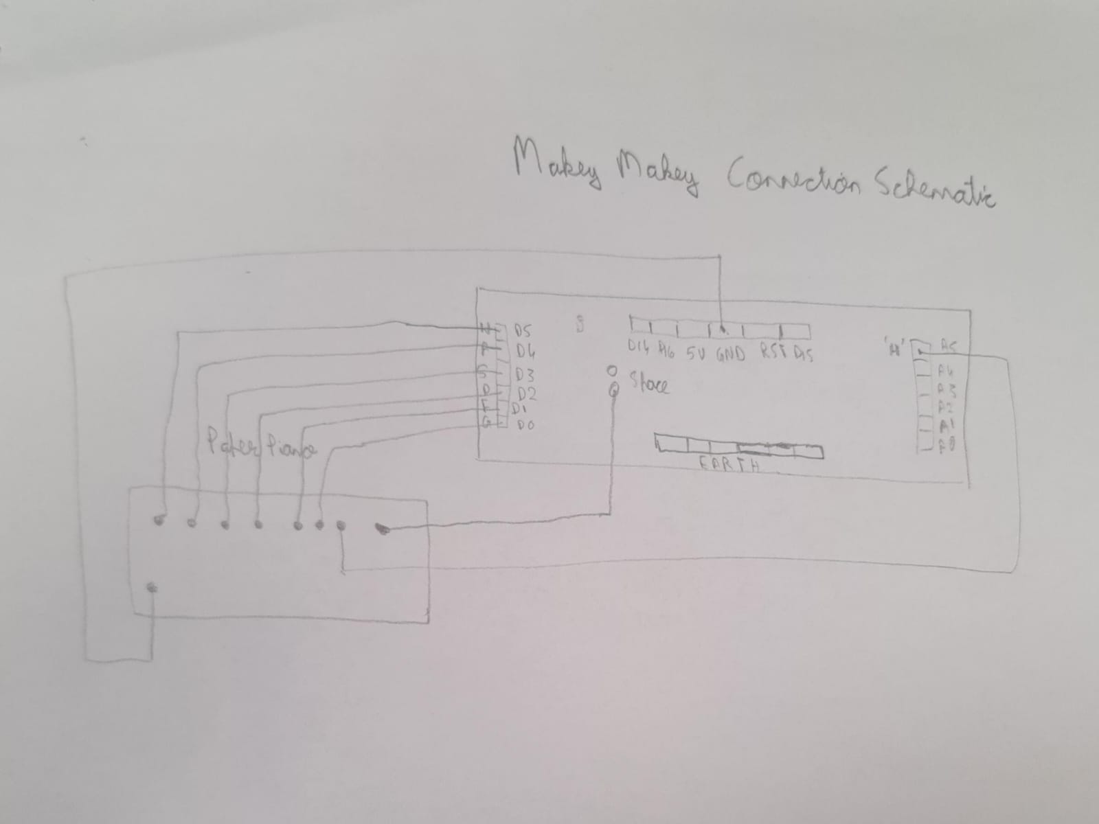
Arduino Code:
const int pulsePin = A0;         // Pulse Sensor connected to analog pin A0
int threshold = 600;             // Set a threshold to detect a beat
bool beatDetected = false;
unsigned long lastBeatTime = 0;
float beatIntervals[30];         // Storage for beat intervals
int beatCount = 0;
unsigned long startTime;
bool measuring = true;           // Change default to 'true' if you want to start measuring immediately
bool countdownActive = false;
unsigned long countdownStartedAt;
const unsigned long countdownDuration = 10000;  // 20 seconds countdown


// LED configuration
const int ledPins[] = {4, 5, 6, 7, 8, 9, 10, 11, 12}; // Digital pins for LED anodes
bool ledsOn = false; // Flag to track if LEDs are currently on


void setup() {
 Serial.begin(9600);
 pinMode(pulsePin, INPUT);


 // Set all LED pins to output mode
 for (int i = 0; i < sizeof(ledPins) / sizeof(int); i++) {
   pinMode(ledPins[i], OUTPUT);
 }
}


void loop() {
 unsigned long currentTime = millis();


 if (measuring) {
   int sensorValue = analogRead(pulsePin);

   if (sensorValue > threshold && !beatDetected) {
     beatDetected = true;
     Serial.println("BEAT");


     if (lastBeatTime > 0 && beatCount < sizeof(beatIntervals) / sizeof(float)) {
       beatIntervals[beatCount++] = currentTime - lastBeatTime;
     }
     lastBeatTime = currentTime;


     // Toggle the LEDs
     toggleLEDs();
   } else if (sensorValue < threshold) {
     beatDetected = false;
   }
 }


 if (countdownActive && currentTime - countdownStartedAt > countdownDuration) {
   countdownActive = false;
   measuring = false; // Stop measuring after countdown
   if (beatCount > 1) {
     float hrv = calculateHRV(beatIntervals, beatCount);
     Serial.print("HRV: ");
     Serial.println(hrv);
   } else {
     Serial.println("Not enough data for HRV.");
   }
   beatCount = 0;


   // Turn off all LEDs after a brief delay
   delay(1000);
   for (int i = 0; i < sizeof(ledPins) / sizeof(int); i++) {
     digitalWrite(ledPins[i], LOW);
   }
 }


 // Check for incoming serial data to reset the measurements
 if (Serial.available() > 0) {
   String command = Serial.readStringUntil('\n');
   command.trim(); // Correct use of trim()
   if (command == "reset") {
     resetMeasurements();
   }
 }


 delay(20);
}


void resetMeasurements() {
 beatCount = 0;
 lastBeatTime = 0;
 measuring = true; // Restart measuring
 countdownActive = false; // Ensure countdown is ready to be triggered again
}


float calculateHRV(float intervals[], int count) {
 if (count == 0) return 0.0; // Avoid division by zero


 float mean = 0;
 for (int i = 0; i < count; i++) {
   mean += intervals[i];
 }
 mean /= count;


 float sd = 0; // Calculate standard deviation of intervals
 for (int i = 0; i < count; i++) {
   sd += pow(intervals[i] - mean, 2);
 }
 sd = sqrt(sd / count);


 return sd; // Return the standard deviation as a measure of HRV
}


void toggleLEDs() {
 // Toggle the state of all LEDs
 ledsOn = !ledsOn;
 for (int i = 0; i < sizeof(ledPins) / sizeof(int); i++) {
   digitalWrite(ledPins[i], ledsOn ? HIGH : LOW);
   }
}
The Arduino code is the brain behind Cupid’s heartbeat detection and LED synchronisation. It starts by setting up the pulse sensor on analog pin A0 and an array of digital pins for the LED heart. In the main loop, it continuously reads the pulse sensor value and compares it to a threshold to determine if a heartbeat is detected. When a beat is sensed, it triggers the LEDs to toggle their state, creating that pulsing heart effect. The code also keeps track of the time between heartbeats, allowing it to calculate the heart rate variability (HRV) after a countdown period. This HRV data is then sent to the p5.js sketch over serial to generate the love predictions.
Finally, I assembled Cupid’s body using cardboard and enclosed all the components inside. I used a laser cutter to create two boxes, one for the head and one for the body. After cutting a small hole in one of the body pieces for the LED heart, I simply used hot glue to put everything together. Adding Cupid’s signature heart face was the finishing touch, completing her look!
User Testing:
Future Improvements:
Detailed Predictions: Right now, Cupid’s predictions are based on general heart rate patterns. But by making these patterns more specific and matching them to different “tones” or themes, her predictions could feel more personal. Small changes in heart rate could lead to fun and unique predictions that match how someone is feeling.
Better Visual Effects: Cupid’s glowing heart is already pretty to look at, but we can make it even more exciting. By adding special effects that move and change with the user’s heartbeat, I can create a more immersive experience. For example, colourful lights that follow the rhythm of your heart, making the whole experience more magical.
Improved Design: Cupid’s current design is cute and friendly, but I can make it even better. By using nicer materials like wood or metal, I can give her a more polished look. Adding moving parts or special lights can also make her feel more alive and engaging.
Final Thoughts:
My favourite part of this project is the LED heart, which not only challenged me but also led to me learning so many new skills. From soldering to wiring, every step was a learning experience that I deeply enjoyed. The illustrations added a delightful touch to the project and contributed to its overall appeal. Seeing the project come together so smoothly and seamlessly was so rewarding.
Apart from that, I’m proud of myself for creating a user experience that evokes feelings of joy and warmth. It required careful consideration of every detail, from the flow of the interaction to the aesthetics. I’m proud that I was able to design an experience that resonates with users, making the interaction with the project enjoyable and memorable.
some more pictures from the showcase 🙂