Steps:

Steps:
Exercise 1:
Ellipse in p5 move on the horizontal axis, in the middle of the screen, and nothing on Arduino is controlled by p5
let rVal = 0;
let alpha = 255;
let left = 0; // True (1) if mouse is being clicked on left side of screen
let right = 0; // True (1) if mouse is being clicked on right side of screen

function setup() {
  createCanvas(640, 480);
  textSize(18);
}

function draw() {
  // one value from Arduino controls the background's red color
  background(255)

  // the other value controls the text's transparency value
  fill(255, 0,0)

  if (!serialActive) {
    text("Press Space Bar to select Serial Port", 20, 30);
  } else {
    text("Connected", 20, 30);
    // Print the current values
    text('rVal = ' + str(rVal), 20, 50);
    text('alpha = ' + str(alpha), 20, 70);
  }

  // click on one side of the screen, one LED will light up
  // click on the other side, the other LED will light up
  if (mouseIsPressed) {
    if (mouseX > rVal-50 && mouseX < rVal+50 && mouseY > height/2-50 && mouseY < height/2+50) {
      right = 1;
    }
  } else {
    right = 0;
  }
  ellipse(rVal, height/2, 50,50)
}

function keyPressed() {
  if (key == " ") {
    // important to have in order to start the serial connection!!
    setUpSerial();
  }
}

// This function will be called by the web-serial library
// with each new line of data. The serial library reads
// the data until the newline and then gives it to us through
// this callback function
function readSerial(data) {
  ////////////////////////////////////
  //READ FROM ARDUINO HERE
  ////////////////////////////////////

  if (data != null) {
    // make sure there is actually a message
    // split the message
    let fromArduino = split(trim(data), ",");
    // if the right length, then proceed
    if (fromArduino.length == 2) {
      // only store values here
      // do everything with those values in the main draw loop

      // We take the string we get from Arduino and explicitly
      // convert it to a number by using int()
      // e.g. "103" becomes 103
      rVal = int(fromArduino[0]);
      alpha = int(fromArduino[1]);
    }

    //////////////////////////////////
    //SEND TO ARDUINO HERE (handshake)
    //////////////////////////////////
    let sendToArduino = left + "," + right + "\n";
    writeSerial(sendToArduino);
  }
}
Exercise 2:
Something that controls the LED brightness from p5
let rVal = 0;
let alpha = 255;
let left = 0; // True (1) if mouse is being clicked on left side of screen
let right = 0; // True (1) if mouse is being clicked on right side of screen

function setup() {
  createCanvas(640, 480);
  textSize(18);
}

function draw() {
  // one value from Arduino controls the background's red color
  background(map(rVal, 0, 1023, 0, 255), 255, 200);

  // the other value controls the text's transparency value
  fill(255, 0, 255, map(alpha, 0, 1023, 0, 255));

  if (!serialActive) {
    text("Press Space Bar to select Serial Port", 20, 30);
  } else {
    text("Connected", 20, 30);
    // Print the current values
    text('rVal = ' + str(rVal), 20, 50);
    text('alpha = ' + str(alpha), 20, 70);
  }


  // click on one side of the screen, one LED will light up
  // click on the other side, the other LED will light up
  if (mouseIsPressed) {
    if (mouseX <= width / 2) {
      left = 1;
    } else {
      right = 1;
    }
  } else {
    left = right = 0;
  }
}

function keyPressed() {
  if (key == " ") {
    // important to have in order to start the serial connection!!
    setUpSerial();
  }
}


function readSerial(data) {
  ////////////////////////////////////
  //READ FROM ARDUINO HERE
  ////////////////////////////////////

  if (data != null) {
    // make sure there is actually a message
    // split the message
    let fromArduino = split(trim(data), ",");
    // if the right length, then proceed
    if (fromArduino.length == 2) {
      // only store values here
      // do everything with those values in the main draw loop

      // We take the string we get from Arduino and explicitly
      // convert it to a number by using int()
      // e.g. "103" becomes 103
      rVal = int(fromArduino[0]);
      alpha = int(fromArduino[1]);
    }

    //////////////////////////////////
    //SEND TO ARDUINO HERE (handshake)
    //////////////////////////////////
    let sendToArduino = left + "," + right + "\n";
    writeSerial(sendToArduino);
  }
}
Exercise 3:
Bouncing ball
let velocity;
let gravity;
let position;
let acceleration;
let breeze;
let drag = 0.99;
let mass = 50;
let heightOfBall = 0;
function setup() {
  createCanvas(640, 360); // Create a canvas of 800x400 pixels

  noFill();
  position = createVector(width/2, 0);
  velocity = createVector(0,0);
  acceleration = createVector(0,0);
  gravity = createVector(0, 0.5*mass);
  breeze = createVector(0,0);
}
function draw() {
  background(215);
  fill(0);

  if (!serialActive) {
    text("Press the space bar to select the serial Port", 20, 50);
  }
  else
  {
    text("check the light.", 20, 50);

  applyForce(breeze);
  applyForce(gravity);
  velocity.add(acceleration);
  velocity.mult(drag);
  position.add(velocity);
  acceleration.mult(0);
  ellipse(position.x,position.y,mass,mass);

  if (position.y > height-mass/2) {
      velocity.y *= -0.9;  // A little dampening when hitting the bottom
      position.y = height-mass/2;

    heightOfBall = 0;

    }
    else {
      heightOfBall = 1;
    }
  }
}
function applyForce(force){
  // Newton's 2nd law: F = M * A
  // or A = F / M
  let f = p5.Vector.div(force, mass);
  acceleration.add(f);
}
function keyPressed() {
  if (key == " ") {
    // important to have in order to start the serial connection!!
    setUpSerial();
  }
}
// this callback function
function readSerial(data) {
    ////////////////////////////////////
    //READ FROM ARDUINO HERE
    ////////////////////////////////////

     if (data != null) {
    // make sure there is actually a message

    let fromArduino = split(trim(data), ",");

       // if the right length, then proceed
    if (fromArduino.length == 1) {
//sensor value is the input from potentiometer
      let sensorVal = int(fromArduino[0]);

//potentiometer value ranges from 0 - 1023
//for values less than 400,wind blows to right
      if (sensorVal < 400){
        breeze.x=1
      }
//if value between 400 and 500, wind stops so ball stops
      else if(sensorVal >= 400 && sensorVal < 500){
        breeze.x = 0
      }
//if value greater than 500, wind blows to left
      else {
        breeze.x = -1
      }
          //////////////////////////////////
          //SEND TO ARDUINO HERE (handshake)
          //////////////////////////////////
    }
//height of ball sent to arduino to check if ball on floor or not
    let sendToArduino = heightOfBall  + "\n";
    writeSerial(sendToArduino);
  }
}
in Arduino:
int leftLedPin = 2;

void setup() {
  // Start serial communication so we can send data
  // over the USB connection to our p5js sketch
  Serial.begin(9600);
  pinMode(LED_BUILTIN, OUTPUT);

  // Outputs on these pins
  pinMode(leftLedPin, OUTPUT);

  // Blink them so we can check the wiring
  digitalWrite(leftLedPin, HIGH);
  delay(200);
  digitalWrite(leftLedPin, LOW);


  // start the handshake
  while (Serial.available() <= 0) {
    digitalWrite(LED_BUILTIN, HIGH); // on/blink while waiting for serial data
    Serial.println("0,0"); // send a starting message
    delay(300);            // wait 1/3 second
    digitalWrite(LED_BUILTIN, LOW);
    delay(50);
  }
}

void loop() {
  while (Serial.available()) {
    digitalWrite(LED_BUILTIN, HIGH); // led on while receiving data

    int left = Serial.parseInt();
    if(left>=330){
       digitalWrite(leftLedPin, HIGH);
}

    if (Serial.read() == '\n') {
      digitalWrite(leftLedPin, left);
      int sensor = analogRead(A0);
      sensor = map(sensor,0,1023,-1,1);
      Serial.println(sensor);

    }
  }
  digitalWrite(leftLedPin, LOW);
}
1- Project Concept
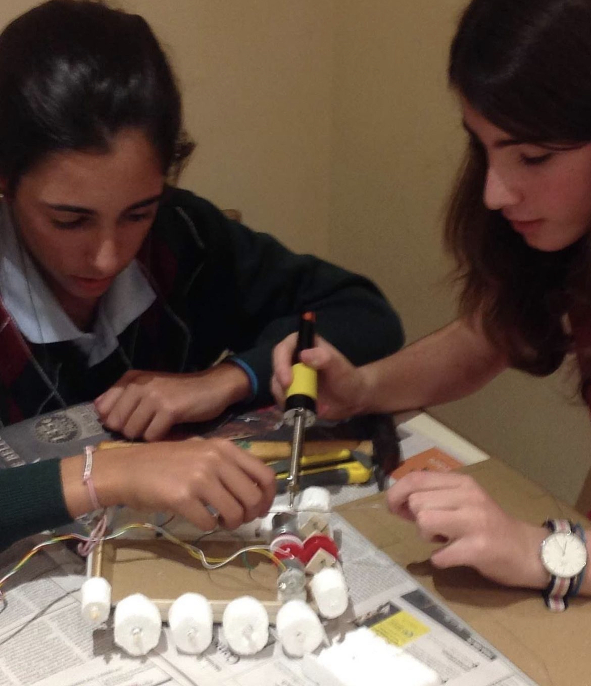
My final project involves designing an automated car that intelligently accesses a parking space. This project is a development of a middle school project I worked on where I made a remote-controlled tank. I’ve now used Arduino to create a self-driving automobile that easily interacts with the P5.js environment thanks to my increased expertise.
2016 Tank: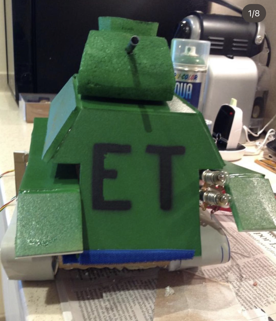
2- Images of the project
link to final project in YouTube: https://www.youtube.com/shorts/cOmEWWDtZFM
https://youtu.be/1EuJl0iAHOQ?si=WrhxC-4yxf5Mujc_
3- User Testing videos
https://www.youtube.com/shorts/SENO-uBmUrs
https://www.youtube.com/shorts/Gj2XIiAjtVc
https://www.youtube.com/shorts/efm2x2616WQ
https://www.youtube.com/shorts/Gj2XIiAjtVc
4- How does the implementation work?
4.1- Description of interaction design
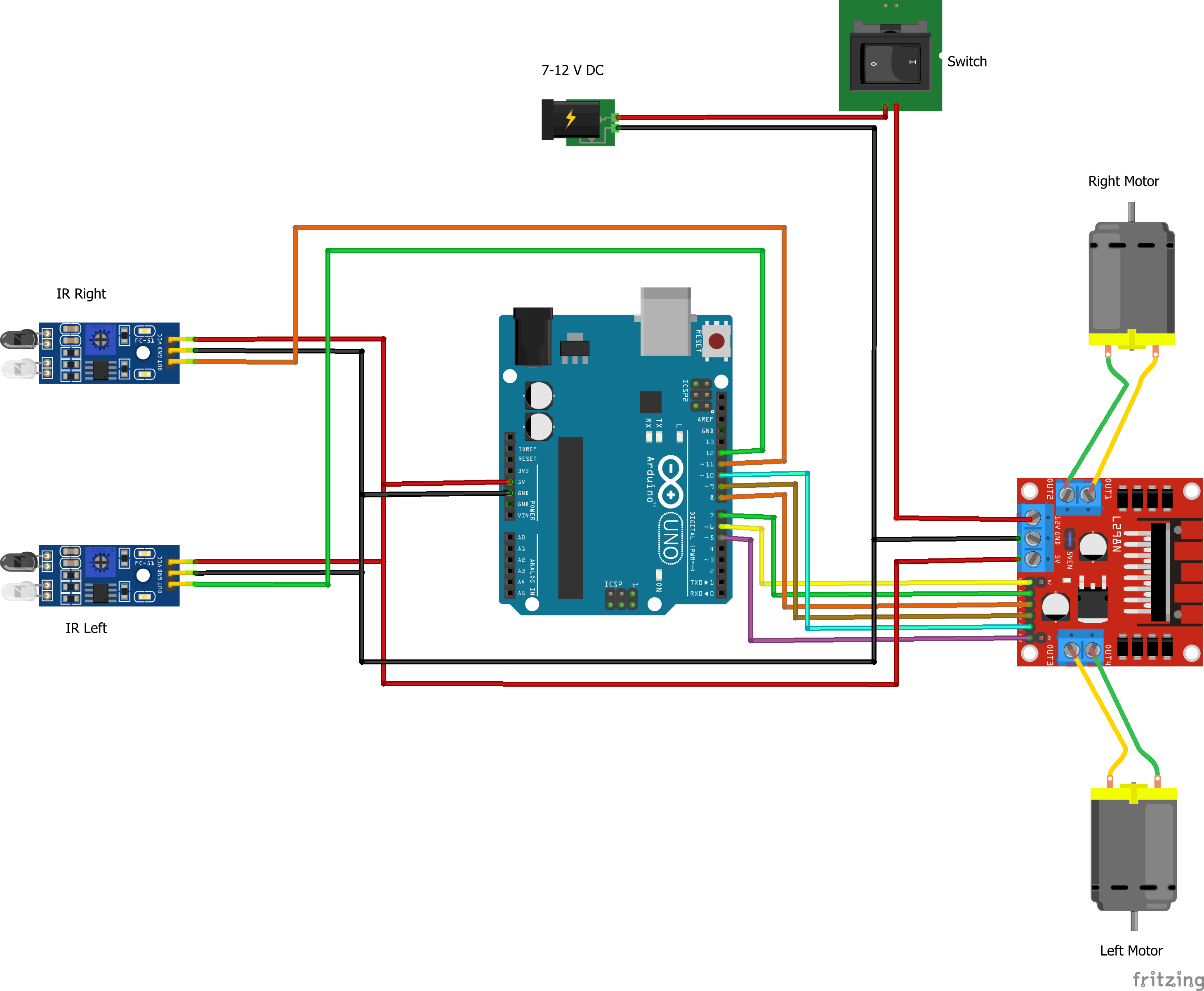
4.2- Description of Arduino code + code snippets
Motor code:
void loop() {
 int rightIRSensorValue = digitalRead(IR_SENSOR_RIGHT);
 int leftIRSensorValue = digitalRead(IR_SENSOR_LEFT);


 Serial.print("Right IR Sensor Value: ");
 Serial.println(rightIRSensorValue);
 Serial.print("Left IR Sensor Value: ");
 Serial.println(leftIRSensorValue);


 if (rightIRSensorValue == HIGH && leftIRSensorValue == HIGH) {

   // Both sensors detect black - move forward
   rotateMotor(-MOTOR_SPEED, -MOTOR_SPEED);
   Serial.println("Both sensors detect black - Moving forward");
 } else if (rightIRSensorValue == LOW && leftIRSensorValue == HIGH) {

   // Right sensor detects white, left detects black - turn right
   rotateMotor(-MOTOR_SPEED, 0);
   while (digitalRead(IR_SENSOR_RIGHT) == LOW) {} // Wait until right sensor detects black
   rotateMotor(-MOTOR_SPEED, -MOTOR_SPEED);
   Serial.println("Right sensor detects white - Turning right");
 } else if (rightIRSensorValue == HIGH && leftIRSensorValue == LOW) {

   // Left sensor detects white, right detects black - turn left
   rotateMotor(0, -MOTOR_SPEED);
   while (digitalRead(IR_SENSOR_LEFT) == LOW) {} // Wait until left sensor detects black
   rotateMotor(-MOTOR_SPEED, -MOTOR_SPEED);
   Serial.println("Left sensor detects white - Turning left");
 } else {

   // Both sensors detect white - stop
   rotateMotor(0, 0);
   Serial.println("Both sensors detect white - Stopping");
 }
}


void rotateMotor(int rightMotorSpeed, int leftMotorSpeed) {

 // Set the direction and speed for the right motor
 digitalWrite(rightMotorPin1, rightMotorSpeed < 0 ? LOW : HIGH);
 digitalWrite(rightMotorPin2, rightMotorSpeed < 0 ? HIGH : LOW);


 // Set the direction and speed for the left motor
 digitalWrite(leftMotorPin1, leftMotorSpeed < 0 ? LOW : HIGH);
 digitalWrite(leftMotorPin2, leftMotorSpeed < 0 ? HIGH : LOW);
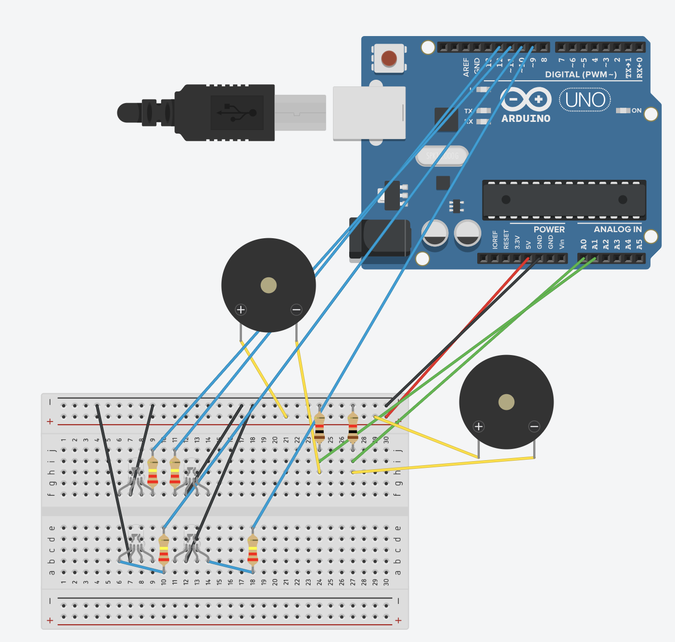
LED+Piezzo:
// LED Pins
const int redLEDPin1 = 12;
const int greenLEDPin1 = 11;
const int redLEDPin2 = 10;
const int greenLEDPin2 = 9;

// Sensor Pins
const int forceSensorPin1 = A0;
const int forceSensorPin2 = A1;

void setup() {
  Serial.begin(9600);

  // Initialize LEDs
  pinMode(redLEDPin1, OUTPUT);
  pinMode(greenLEDPin1, OUTPUT);
  pinMode(redLEDPin2, OUTPUT);
  pinMode(greenLEDPin2, OUTPUT);

  // Initialize Sensors
  pinMode(forceSensorPin1, INPUT);
  pinMode(forceSensorPin2, INPUT);
}

void loop() {
  int sensorValue1 = analogRead(forceSensorPin1);
  int sensorValue2 = analogRead(forceSensorPin2);
  Serial.print("Sensor 1: ");
  Serial.print(sensorValue1);
  Serial.print(" Sensor 2: ");
  Serial.println(sensorValue2);

  // Control for first set of LEDs
  if (sensorValue1 > 90) {
    digitalWrite(redLEDPin1, HIGH);
    digitalWrite(greenLEDPin1, LOW);
  } else {
    digitalWrite(redLEDPin1, LOW);
    digitalWrite(greenLEDPin1, HIGH);
  }

  // Control for second set of LEDs
  if (sensorValue2 > 100) {
    digitalWrite(redLEDPin2, HIGH);
    digitalWrite(greenLEDPin2, LOW);
  } else {
    digitalWrite(redLEDPin2, LOW);
    digitalWrite(greenLEDPin2, HIGH);
  }
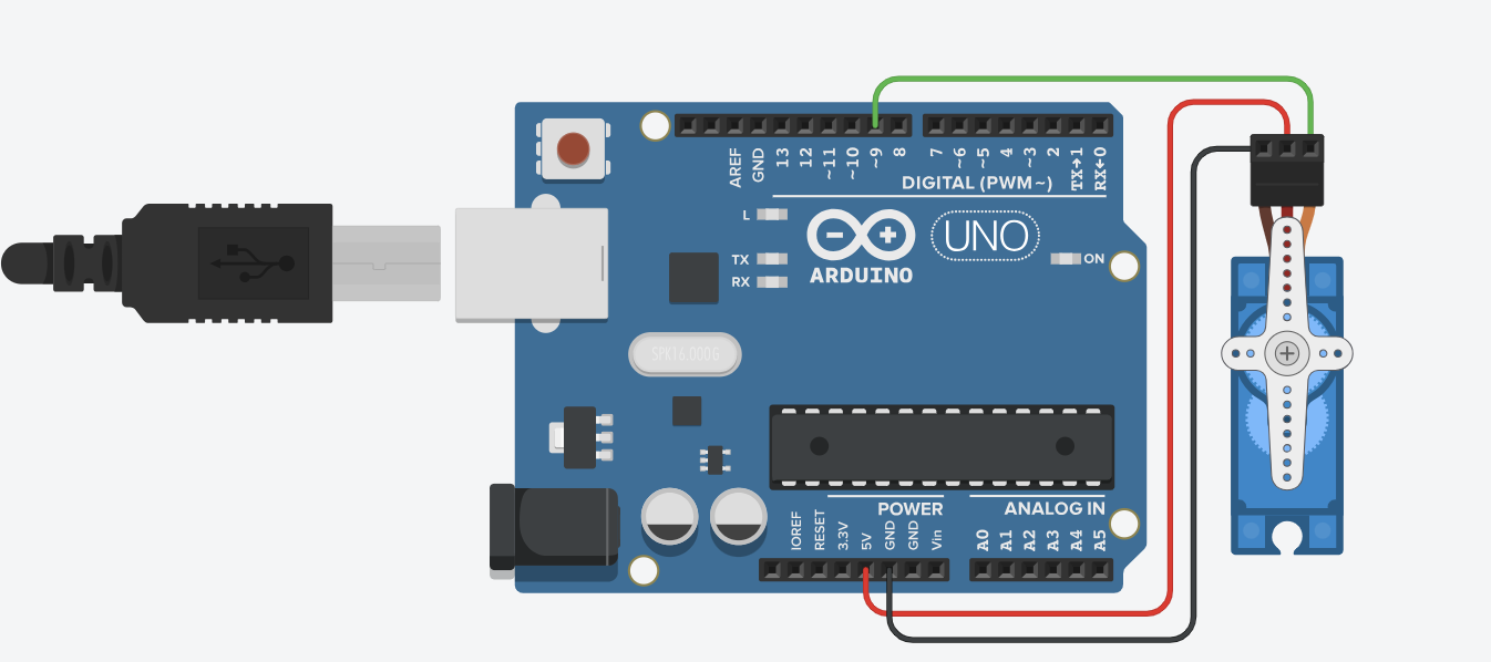
Servo & serial communication:
#include <Servo.h>

Servo myservo;
const int servoPin = 9;

void setup() {
  myservo.attach(servoPin);
  Serial.begin(9600);
  while (!Serial); // Wait for serial port to connect. Needed for native USB port only
  Serial.println("Serial ready"); // Send ready message once serial is set up
  myservo.write(0); // Initialize servo to 0 degrees
}

void loop() {
  if (Serial.available() > 0) {
    String command = Serial.readStringUntil('\n');
    command.trim();
    if (command == "OPEN") {
      rotateServo();
      Serial.println("Gate opened"); // Acknowledge the command execution
    }
  }
}

void rotateServo() {
  myservo.write(90);
  delay(10000);
  myservo.write(0);
}
4.3- Description of p5.js code + code snippets + embedded sketch
https://editor.p5js.org/ec4237/sketches/tGJTp0jqi
function startPresentation() {
  if (!serialActive) {
    // Attempt to set up serial directly in response to the button click
    setUpSerial().then(() => {
      console.log("Serial setup complete, starting presentation.");
      fullscreen(true);
      slideNumber = 0;
      startButton.hide();
    }).catch(error => {
      console.error("Failed to set up serial:", error);
      // Inform the user to retry or check permissions
      alert("Failed to set up serial. Please ensure you allow serial access and try again.");
    });
  } else {
    console.log("Serial already set up, starting presentation.");
    fullscreen(true);
    slideNumber = 0;
    startButton.hide();
  }
}

function getMessage() {
  switch (slideNumber) {
    case 0:
      return "Press 'Continue' to open the gate!";  // Initial message to open the gate
    case 1:
      return "Let's start the drive! Please turn on the car by clicking the central switch.";  // Message to start the car after gate opens
    case 2:
      return "Proceed to Parking Spot 2";  // Final slide message
  }
}

function nextSlide() {
  console.log(`Current slide before increment: ${slideNumber}`);
  if (slideNumber === 0) {
    console.log("Ready to open the gate.");
    sendOpenGateCommand(); // Sends command to open the gate
  } else {
    slideNumber++;  // Increment to move to the next slide for other cases
  }
  console.log(`Moved to slide: ${slideNumber}`);

  if (slideNumber < 2) {
    continueButton.show();
  } else if (slideNumber === 2) {
    continueButton.show();
  } else {
    slideNumber = 0;  // Reset slide number
    continueButton.hide();  // Hide continue button
    console.log("Reset slides and hid continue button.");
  }
}


function sendOpenGateCommand() {
  console.log("Serial already active. Now sending 'OPEN' command.");
  writeSerial('OPEN\n');
  slideNumber++;  // Increment after sending the command
}
4.4- Description of communication between Arduino and p5.js
Arduino and P5 communicate through serial communication when the user clicks to open the gate by pushing a screen button.
5- What are some aspects of the project that you’re particularly proud of?
6- Links to resources used
https://github.com/un0038998/LineFollowerRobot/blob/main/Diagrams/LineFollwerRobot.png
https://www.instructables.com/Line-Follower-Robot-Using-Arduino-2/
7- Challenges faced and how you tried to overcome them
Initially, the original plan was that the user placed a car in P1 or P2. The IRS weight sensor would detect the car in the occupied space and send a message in P5 saying that the car should go to the free parking space. Subsequently, the car would go to the unoccupied parking slot. The problem was that I could not figure out the communication between P5 and Arduino. The car got confused when it had to choose whether to go left or right. Therefore, what I did was to have a predetermined route to P1. It is less interactive but I didn’t have the time to investigate a bit deeper. This problem tighs with the next question about future improvements.
Another challenge I faced was the initial connections of the car. I had a problem connecting the switch and the motor shield to the motors.
Additionally, my IRS sensors broke, so I replaced them with piezzo sensors. However, upon connecting the new sensors, I noticed they couldn’t accurately measure the weight of the car because they failed to detect the material of the wheels. Consequently, I sought out another pair of weight sensors capable of identifying the car wheel material.
8- What are some areas for future improvement?
There are a lot of areas that need improvement. 🙂
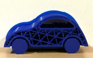
Starting from the design of the car. I would like to have used the laser cutting machine to make a chassis so that it looked a bit more real.
I envisioned a scenario where the user could select a parking slot, and the car robot would autonomously navigate to the opposite slot. My preference was for the car to navigate without the need for a black line to follow. Initially, I aimed for a fully autonomous vehicle. However, achieving this goal demands additional computational skills beyond my current capabilities.
Originally, I intended to equip the car with an ultrasonic sensor programmed to detect objects and trigger a pause. The concept involved the motors stopping when the ultrasonic sensor detected proximity to an object, prompting the buzzer to emit a two-second beep (similar to cars alerting you of imminent collision). I began coding the buzzer to work in tandem with the ultrasonic sensor, but due to time constraints, I couldn’t complete it. Within the limited timeframe, I struggled to devise a mechanism to temporarily stop the motor upon detection of an obstacle and resume its operation once the obstacle was no longer present.
The weight sensor for the car doesn’t always work. I would have liked to make a bigger area for the sensor to detect it more accurately.
9- IM show documentation, images, videos, and people interacting with your project
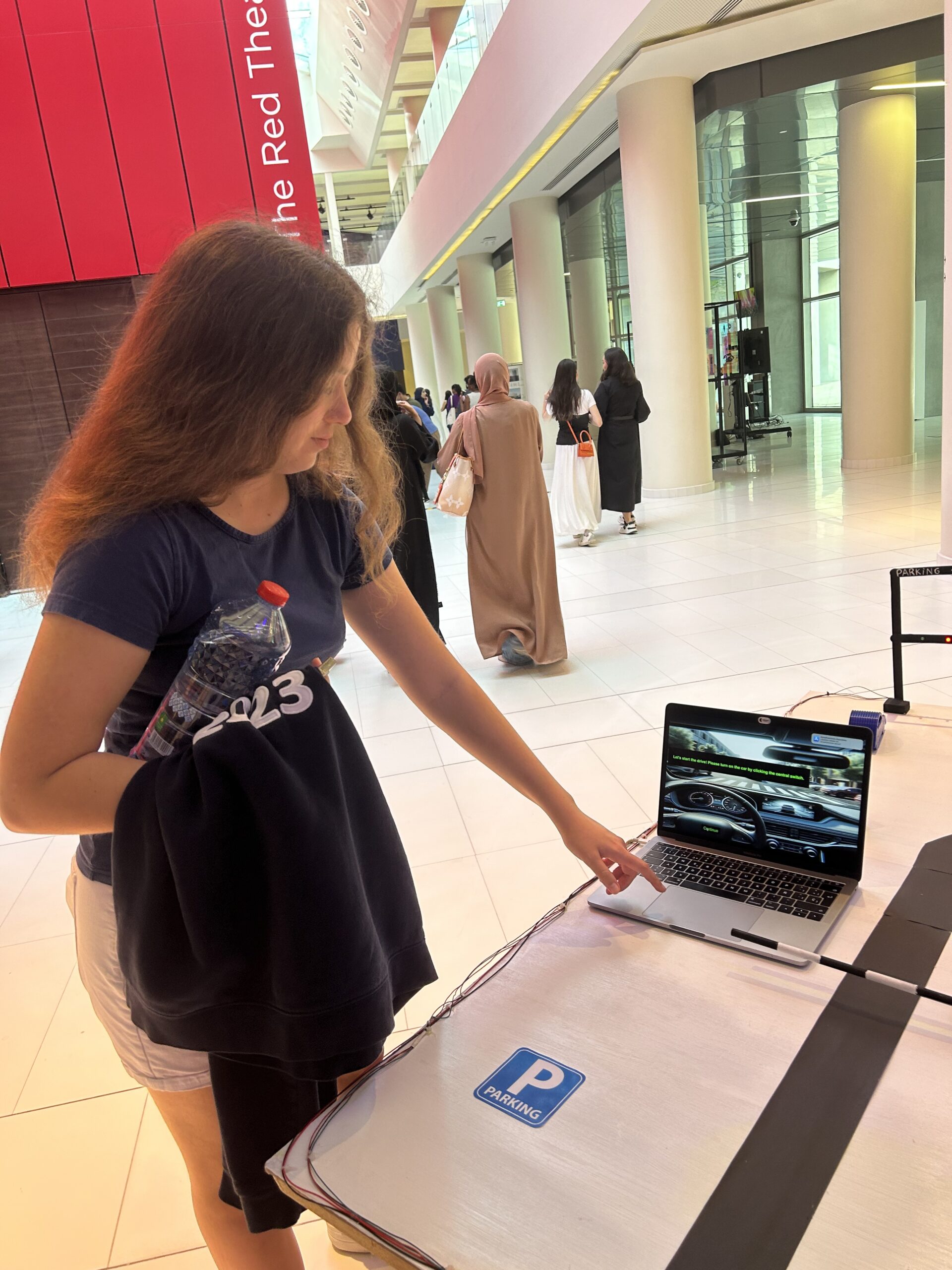
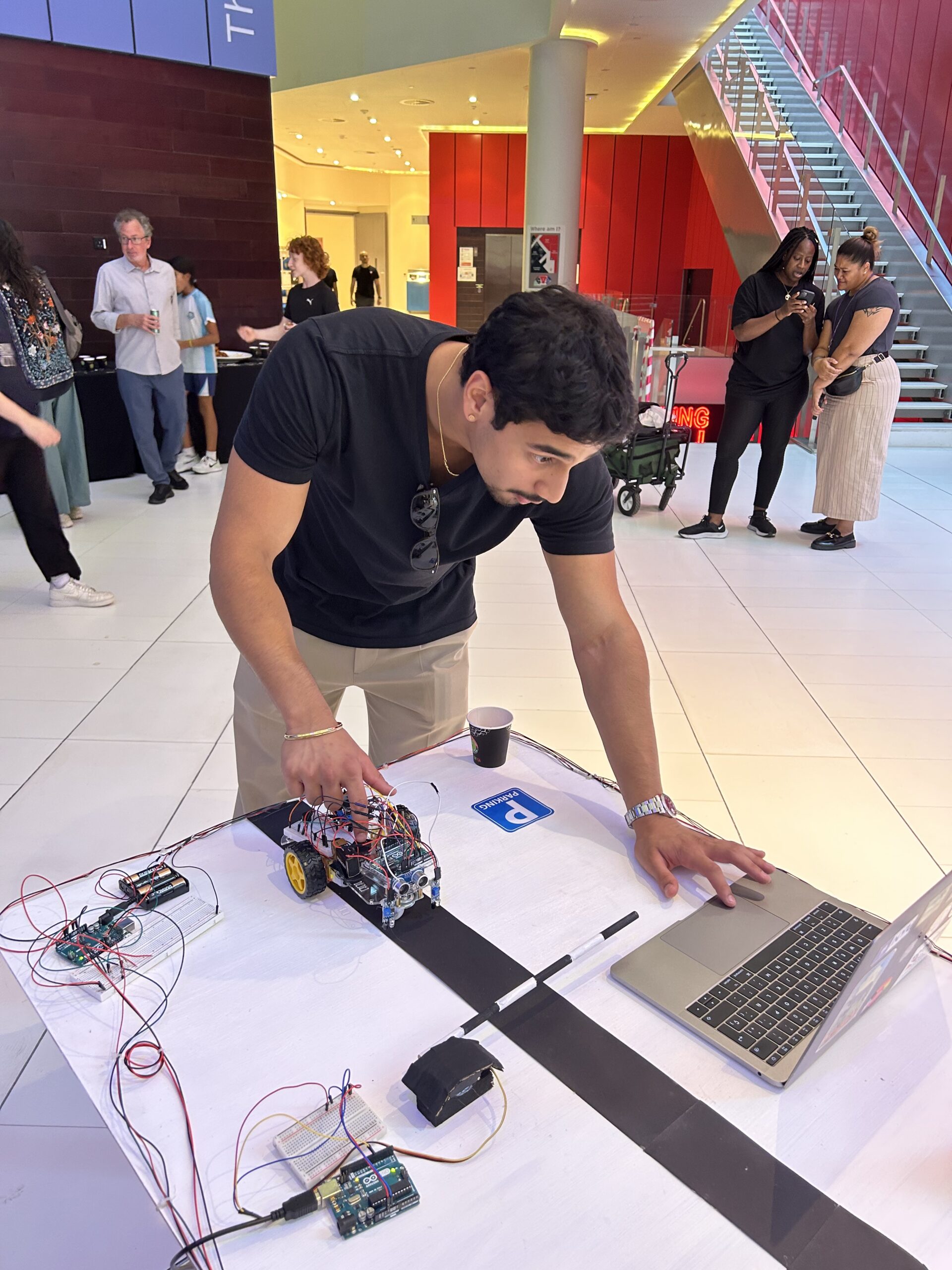
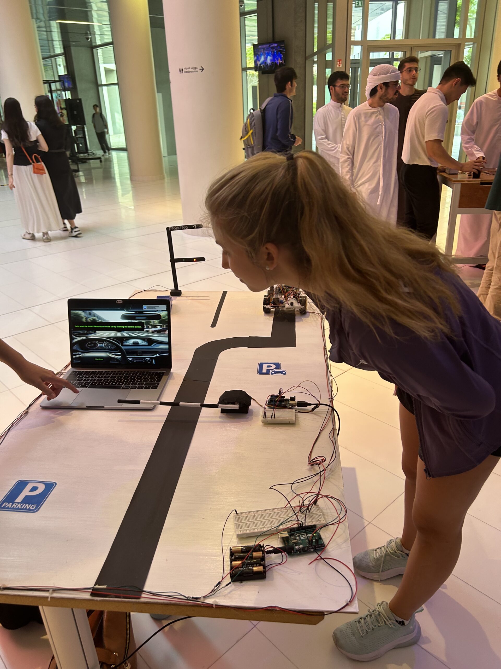
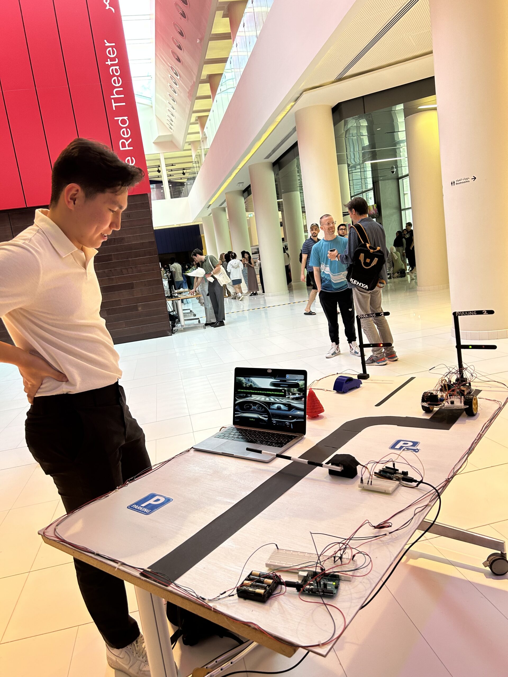
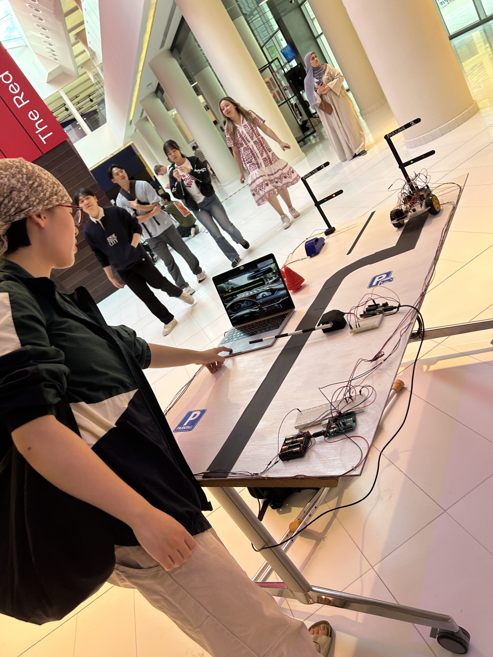
Overall, this project is something I am very proud of. I’ve learned so much and I’ve had a lot of fun 😉
Appendix:
Full car code
#include <Arduino.h>


// Define IR sensor pins
#define IR_SENSOR_RIGHT 11
#define IR_SENSOR_LEFT 12


// Define motor speed constant
#define MOTOR_SPEED 180


// Define pins for right motor
int enableRightMotor = 6;
int rightMotorPin1 = 7;
int rightMotorPin2 = 8;


// Define pins for left motor
int enableLeftMotor = 5;
int leftMotorPin1 = 9;
int leftMotorPin2 = 10;


void setup() {
 // Set the PWM frequency for motor control
 TCCR0B = TCCR0B & B11111000 | B00000010;  // Set frequency to 7812.5 Hz
  // Initialize motor control pins
 pinMode(enableRightMotor, OUTPUT);
 pinMode(rightMotorPin1, OUTPUT);
 pinMode(rightMotorPin2, OUTPUT);
  pinMode(enableLeftMotor, OUTPUT);
 pinMode(leftMotorPin1, OUTPUT);
 pinMode(leftMotorPin2, OUTPUT);


 // Initialize IR sensor pins
 pinMode(IR_SENSOR_RIGHT, INPUT);
 pinMode(IR_SENSOR_LEFT, INPUT);
  // Initialize serial communication at 9600 baud for debugging
 Serial.begin(9600);
  // Stop motors initially
 rotateMotor(0, 0);
}


void loop() {
 int rightIRSensorValue = digitalRead(IR_SENSOR_RIGHT);
 int leftIRSensorValue = digitalRead(IR_SENSOR_LEFT);


 Serial.print("Right IR Sensor Value: ");
 Serial.println(rightIRSensorValue);
 Serial.print("Left IR Sensor Value: ");
 Serial.println(leftIRSensorValue);


 if (rightIRSensorValue == HIGH && leftIRSensorValue == HIGH) {

   // Both sensors detect black - move forward
   rotateMotor(-MOTOR_SPEED, -MOTOR_SPEED);
   Serial.println("Both sensors detect black - Moving forward");
 } else if (rightIRSensorValue == LOW && leftIRSensorValue == HIGH) {

   // Right sensor detects white, left detects black - turn right
   rotateMotor(-MOTOR_SPEED, 0);
   while (digitalRead(IR_SENSOR_RIGHT) == LOW) {} // Wait until right sensor detects black
   rotateMotor(-MOTOR_SPEED, -MOTOR_SPEED);
   Serial.println("Right sensor detects white - Turning right");
 } else if (rightIRSensorValue == HIGH && leftIRSensorValue == LOW) {

   // Left sensor detects white, right detects black - turn left
   rotateMotor(0, -MOTOR_SPEED);
   while (digitalRead(IR_SENSOR_LEFT) == LOW) {} // Wait until left sensor detects black
   rotateMotor(-MOTOR_SPEED, -MOTOR_SPEED);
   Serial.println("Left sensor detects white - Turning left");
 } else {

   // Both sensors detect white - stop
   rotateMotor(0, 0);
   Serial.println("Both sensors detect white - Stopping");
 }
}


void rotateMotor(int rightMotorSpeed, int leftMotorSpeed) {

 // Set the direction and speed for the right motor
 digitalWrite(rightMotorPin1, rightMotorSpeed < 0 ? LOW : HIGH);
 digitalWrite(rightMotorPin2, rightMotorSpeed < 0 ? HIGH : LOW);


 // Set the direction and speed for the left motor
 digitalWrite(leftMotorPin1, leftMotorSpeed < 0 ? LOW : HIGH);
 digitalWrite(leftMotorPin2, leftMotorSpeed < 0 ? HIGH : LOW);


 // Apply PWM to the motors
 analogWrite(enableRightMotor, abs(rightMotorSpeed));
 analogWrite(enableLeftMotor, abs(leftMotorSpeed));
}
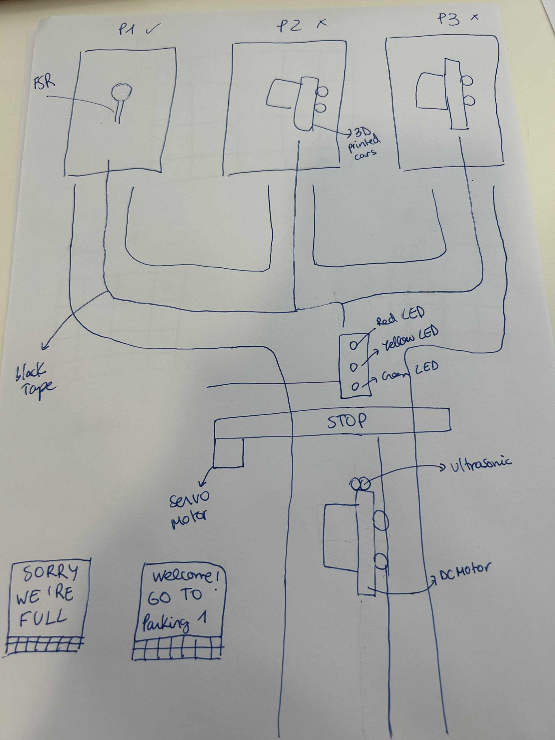
I am going to build a parking for a self-driving car that parks itself.
There are various steps for building this parking.
First of all, I am going to concentrate on building the self-driving car. This car will follow a black line on the ground.
Functioning:
The car will drive straight. When the ultrasonic sensor detects the parking bar it will stop. Here is where all the parking function starts.
The parking will detect if there are free slots in the parking. If there is no room for the car, the P5 will tell the driver “Sorry, we’re full” and the red traffic light will light up. If there is an available slot a message in P5 will appear saying “Welcome, go to parking X (and the number). When this message is displayed the Stop bar will open controlled by a servo motor, the green LED in the traffic light will light and the car will go to the available spot.
(Question, how do I make the self-driving car go to the free parking slot)
Once the car is on top of the free parking slot the FSR(force-sensitive resistor) will detect the car and turn the traffic light red. the ultrasonic resistor will stop as it will detect the parking wall.
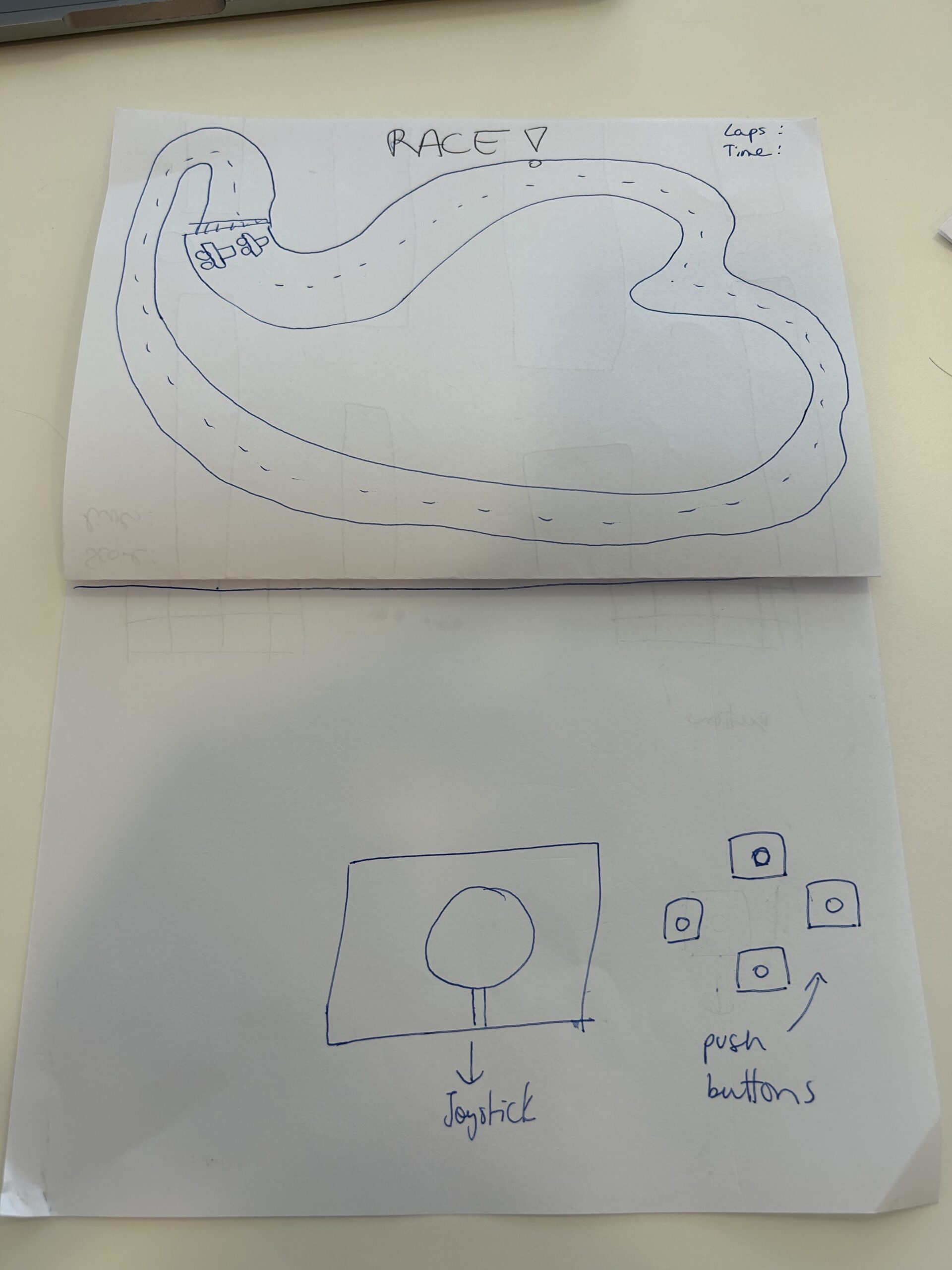
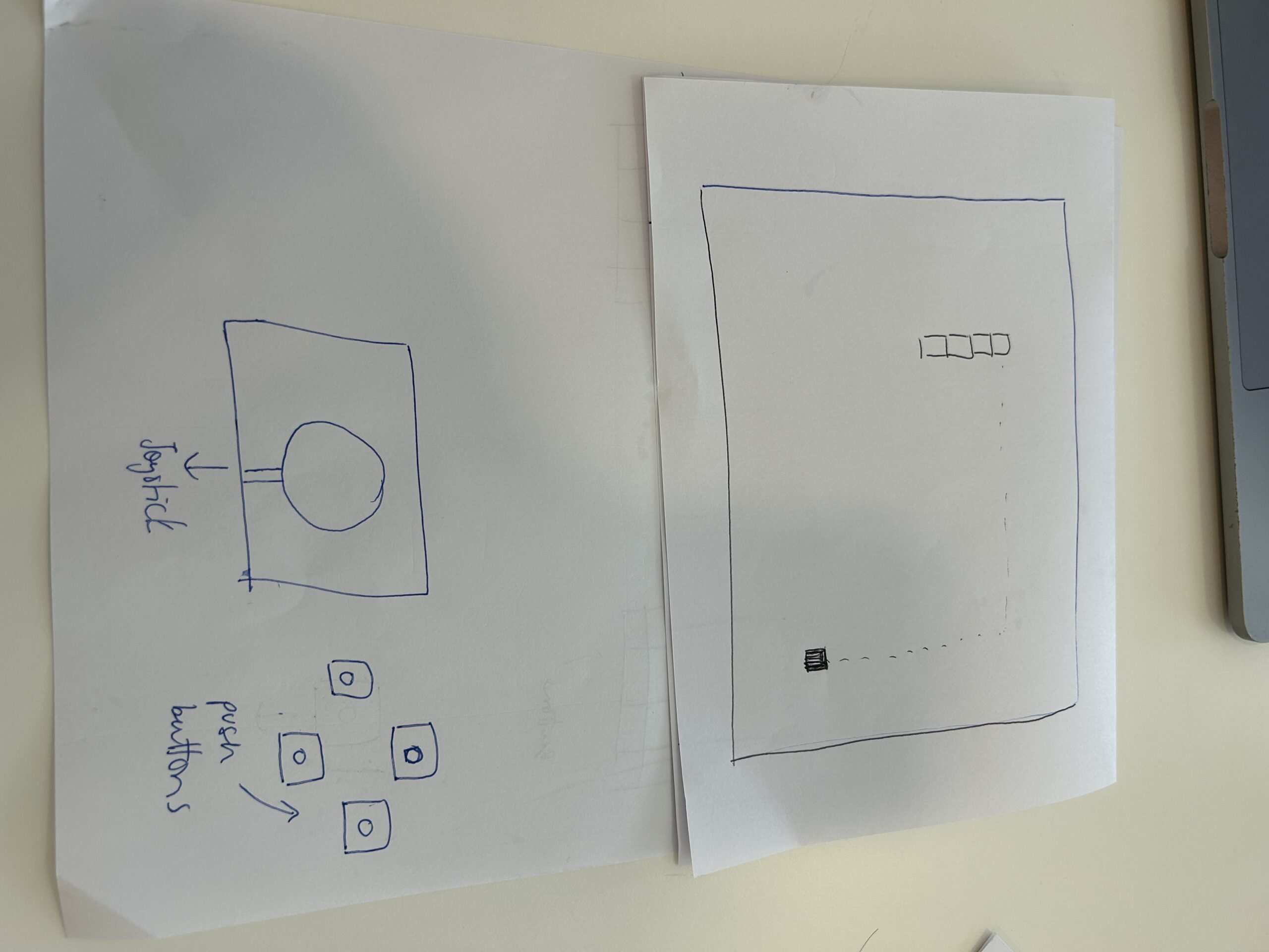
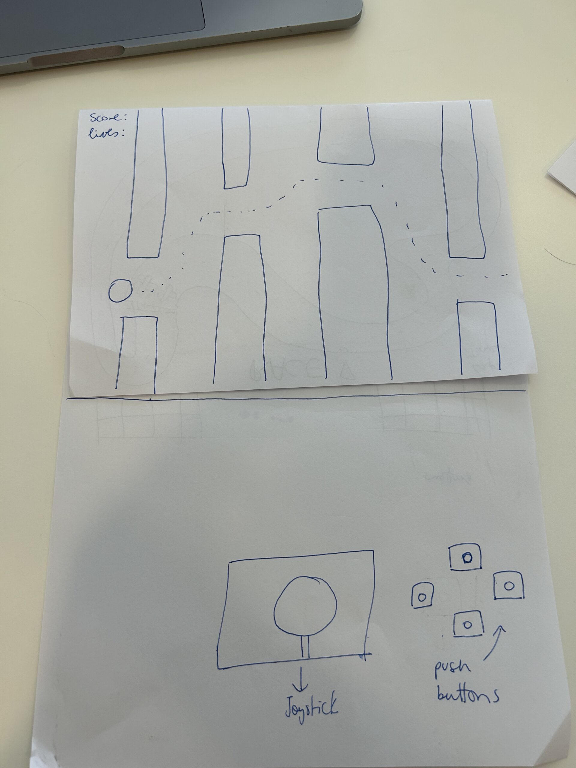
Idea 1:
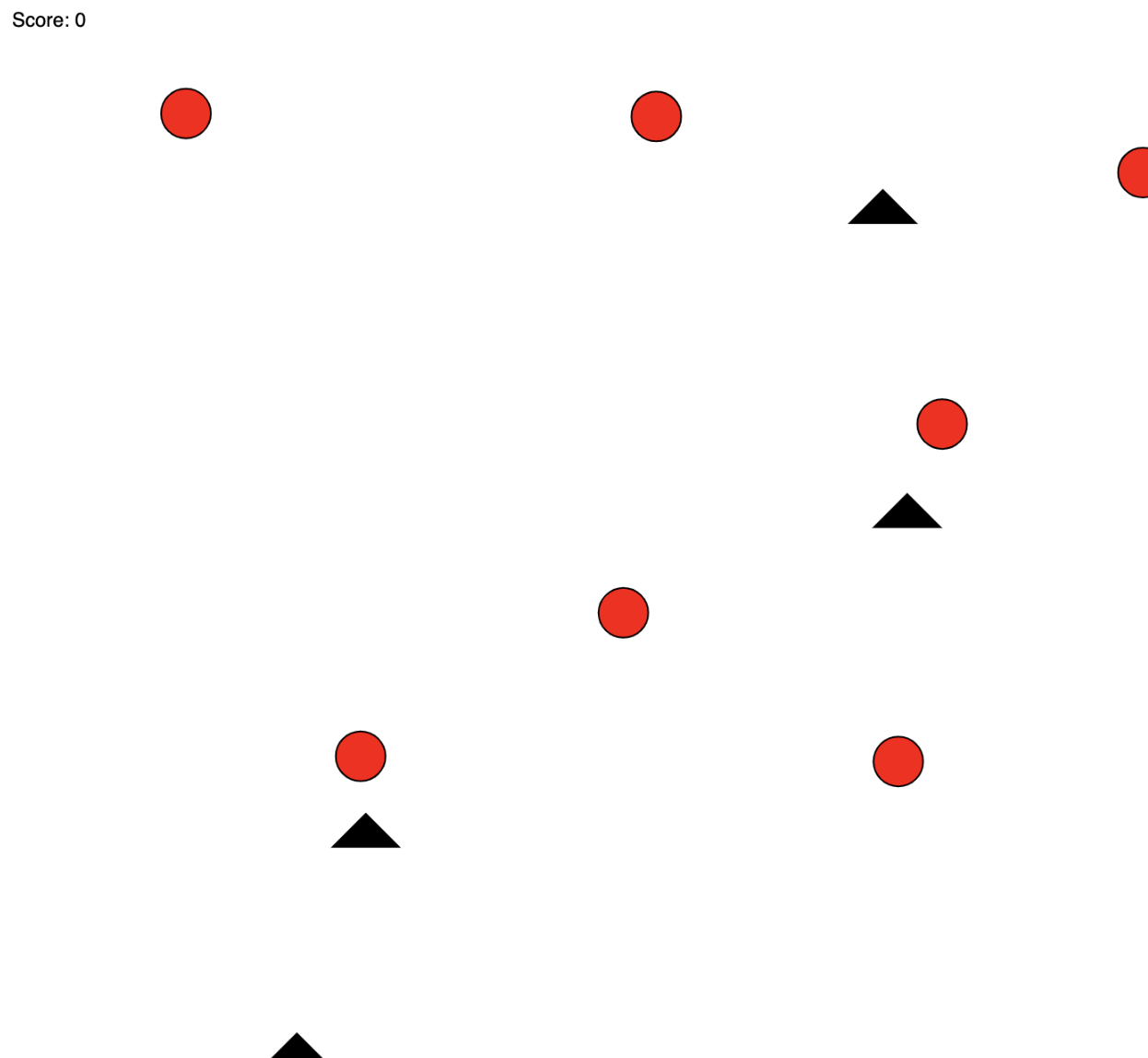
Built a joystick and control a car in a game in p5
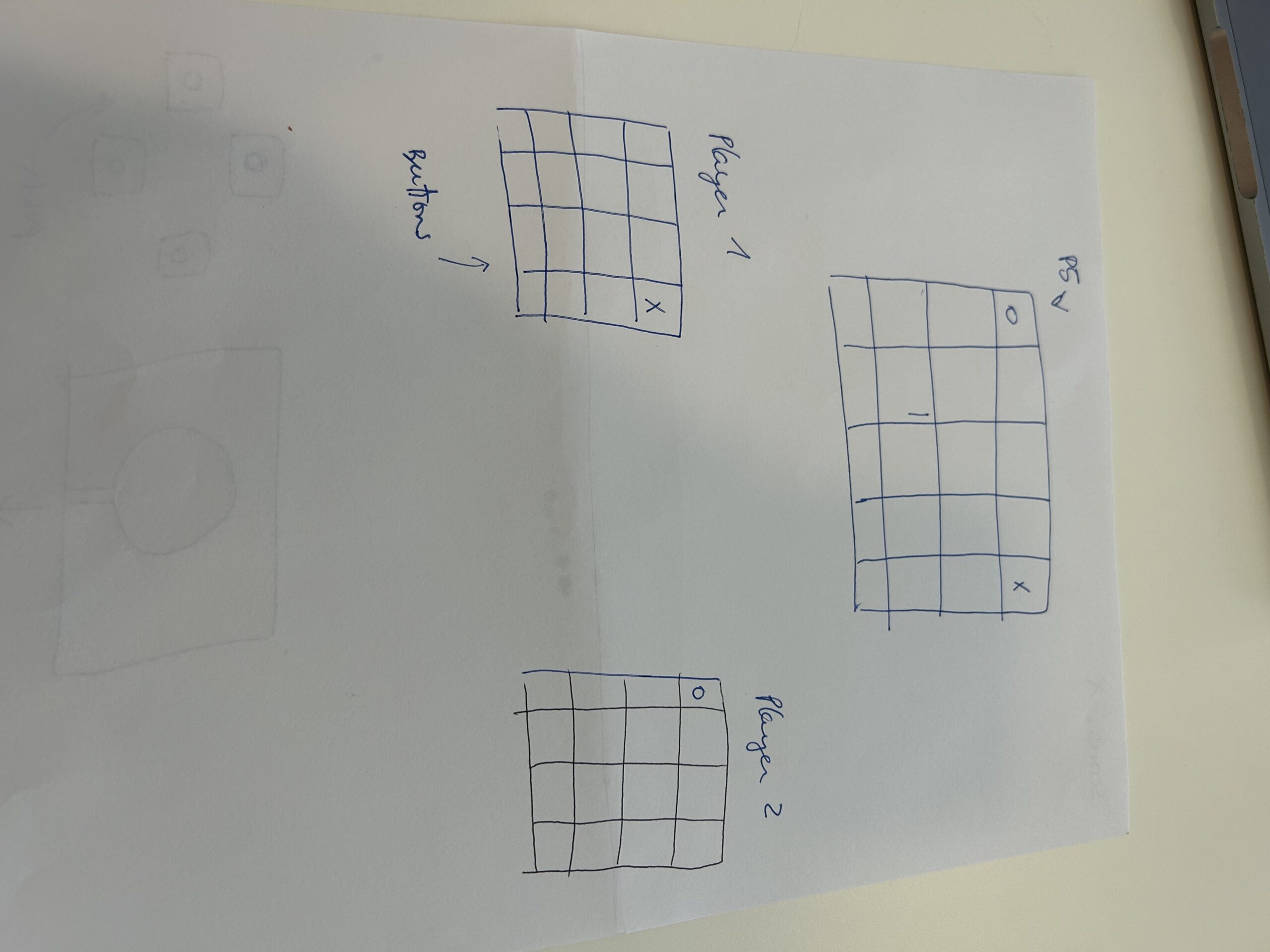
Idea 2:
3 in a row game. 9 buttons on the Arduino board and in p5 the board game.
Idea 3:
build a sensor ultrasonic car that detects objects near it
Design Meets Disability:
https://intro.nyuadim.com/wp-content/uploads/2020/08/Design_meets_disability.pdf
In the reflection article on Graham Pullin’s book “Design Meets Disability,” important themes are discussed that relate design principles to real-world requirements and societal views on disability. Pullin is a proponent of minimalist design, contending that functionality demands it, particularly when creating for people with disabilities. I identify with this point of view since it goes against the grain of conventional thinking, which prioritizes aesthetics over usefulness. The user experience can be greatly improved by both useful and aesthetically pleasing aspects, therefore I find myself thinking about how to strike a balance between both.
An important ethical problem arises from Pullin’s claim that “disability inspires design” and that such designs should strive to make the user blend into their environment. It implies a hidden desire to hide a disability, which could reinforce the stigma instead than celebrating variety. Pullin uses eyewear as an example of how design and function can be successfully combined, turning glasses from basic medical devices into fashionable accessories that are generally accepted in society. This change demonstrates how design has the ability to affect society norms and perceptions.
But this begs the question of whether the goal of design ought to be to celebrate individuality and promote empowerment, or to assist people with disabilities in “blending in.” It may be restrictive to assume that excellent design equals to being discrete, as design has the power to question and transform social norms.
Furthermore, while its importance, Pullin’s emphasis on usefulness and simplicity ignores the nuanced interactions that exist between a person’s identity and their tools or assistance. This error makes me wonder about the possibilities of design as a means of expressing uniqueness as well as serving as a functional solution. Could designs celebrate and reflect the variety of user experiences in addition to meeting practical needs?
The book “Design Meets Disability” definitely made me rethink design concepts by highlighting how important it is to take an inclusive approach that prioritizes both beauty and practicality. It also made people think more deeply about how designs affect how society perceives identity and disability. After reading this, I’m left feeling that there are a lot of opportunities for careful design to make the world more inclusive.
Project description:
This project involves using LEDs, buttons, a potentiometer, and a buzzer to create a fun and interactive experience. Below is a summary of how it works and what was learned.
Key Components:
Instrument:
https://youtube.com/shorts/6Bm-7NDI3RM?si=Vu55mtSy6QuivNm8
Code:
const int redLED = 6;
const int greenLED = 5;
const int yellowLED = 7;
const int redButton = 12;
const int greenButton = 11;
const int yellowButton = 13;
const int potPin = A2;
const int buzzerPin = 3;

void setup() {
  pinMode(redLED, OUTPUT);
  pinMode(greenLED, OUTPUT);
  pinMode(yellowLED, OUTPUT);

  pinMode(redButton, INPUT_PULLUP);
  pinMode(greenButton, INPUT_PULLUP);
  pinMode(yellowButton, INPUT_PULLUP);

  // Initialize Serial for debugging
  Serial.begin(9600);
}

void loop() {
  // Read potentiometer value
  int potValue = analogRead(potPin);
  // Map potentiometer value to a frequency range (e.g., 100 Hz to 2000 Hz)
  int frequency = map(potValue, 0, 1023, 100, 2000);

  // Check each button and activate the corresponding LED and buzzer
  if (digitalRead(redButton) == LOW) {
    digitalWrite(redLED, HIGH);
    tone(buzzerPin, frequency);  // Play buzzer at mapped frequency
    delay(100);  // delay
  } else {
    digitalWrite(redLED, LOW);
  }

  if (digitalRead(greenButton) == LOW) {
    digitalWrite(greenLED, HIGH);
    tone(buzzerPin, frequency + 100);  // Slightly higher pitch for green button
    delay(100);  // Debounce delay
  } else {
    digitalWrite(greenLED, LOW);
  }

  if (digitalRead(yellowButton) == LOW) {
    digitalWrite(yellowLED, HIGH);
    tone(buzzerPin, frequency + 200);  // Even higher pitch for yellow button
    delay(100);  // Debounce delay
  } else {
    digitalWrite(yellowLED, LOW);
  }
  delay(10);
}
Reflections:
Watching the LEDs light up and hearing the buzzer change pitch was very rewarding. It’s fascinating to see how basic parts and some coding can create a captivating interactive experience. Adjusting the buzzer’s pitch with the potentiometer was particularly enjoyable, as it required fine-tuning to get pleasant sounds and smooth transitions between pitches.
Challenges:
Improvements:
A Brief Rant On The Future Of Interaction Design
https://worrydream.com/ABriefRantOnTheFutureOfInteractionDesign/
Introduction (Summary):
“A Brief Rant on the Future of Interaction Design” by Brett Victor is a critique of the direction that interaction design is currently taking. In particular, he takes issue with the fixation on “pictures under glass,” as most interactions are limited to swiping a flat screen. Victor is a champion of designs that make full use of our hands and body, appealing to more of our senses.
Thought (Personal Impact):
Victor’s enthusiastic defense of technology caused me to reevaluate its actual possibilities. His criticism of the pervasive touchscreens made me think of the enjoyable tactile feedback that conventional controls, such as knobs and sliders in music equipment, offer, something touchscreens do not. His viewpoint, which revealed a stalemate in truly inventive consumer technology interfaces, was both energizing and alarming.
Perspective Shift:
The essay caused me to reconsider what I consider to be “innovative” technology. In the past, I associated advancement with devices that were slimmer and had more fluid touch interfaces. Victor’s focus on tactile engagement offers a more expansive meaning of innovation, one that goes beyond merely digitizing human interaction and capability enhancement. His illustrations of more tactile and expressive experiences, such as making music or shaping clay, are potent reminders of the dimensions we lose when we depend just on touchscreen technology.
Novel Thoughts and Important Concerns:
I’m left wondering after reading this essay why interface design’s greater potential isn’t being investigated more thoroughly. Victor mentions this, but he doesn’t go into detail as to why the industry strongly favors touchscreens. Is it because of customer demand, simplicity of manufacturing, or maybe a lack of vision in the tech sector? This lack of conversation is a crucial component in comprehending the obstacles to the ideas Victor supports.
Conclusion:
I find it impossible to see how existing technologies, such as iPads and tablets, could be improved to greatly improve their physical involvement outside of the touchscreen concept. It appears that a different form of technology and product may be needed, one that radically rethinks how we use technology. Furthermore, we see a tendency toward even less hand use with the introduction of VR glasses, pointing to a time when manual engagement may become unnecessary. Victor’s appeal to rethink interaction design, highlighting the necessity to maintain and improve physical engagement in our increasingly digital environment, is made all the more meaningful by this tendency.
Responses: A Brief Rant on the Future of Interaction Design
https://worrydream.com/ABriefRantOnTheFutureOfInteractionDesign/responses.html
Bret When one considers how interaction design affects children, Victor’s criticism of contemporary interaction design in “A Brief Rant on the Future of Interaction Design” is particularly poignant. Victor highlights that instead of restricting interactions to “pictures under glass,” there is a need for more tactile and physically engaging interfaces. His interest for the learning and sensory development of youngsters is one really insightful feature. Children may grow reluctant to participate in more hands-on activities like building, crafting, or exploring the natural world if interactions are limited to touchscreens. This restriction may intensify anxieties about getting filthy, using real toys, and even connecting with the outdoors and animals. The article got me thinking about how modern technological trends might affect children’s perception of and interactions with their physical surroundings, in addition to changing how they learn. This could potentially impede children’s natural tendency toward exploration and general development.
Physical Computing’s Greatest Hits (and misses)
It became clear to me after reading “Physical Computing’s Greatest Hits (and misses)” that old concepts in physical computing may be updated to create something fresh and innovative. The piece goes through a number of projects, such as interactive pads and musical instruments, to demonstrate how amazing inventions can result from reimagining old concepts in fresh ways. It’s a fun reminder that often the most innovative ideas are simply the greatest old ones with a little tweaking.
I was particularly drawn to three items, which caused me to reconsider my previous thoughts. I was first shown that you are not limited to traditional methods of creating music by experimenting with making music with movements, such as with theremin-like devices. This helped me to see how our creative expression can be altered by actual computers. Second, the combination of digital technology with real-world artifacts to create images made “Mechanical Pixels” quite fascinating. This innovative approach to digital pictures gives it a more vibrant, more engaging feeling. Last but not least, the section on “Multitouch Interfaces” got me to reflect on how we utilize technology. It brought to light that, despite its coolness, touchscreens fail to provide us with tactile feedback—a crucial feature. This got me thinking about how gadgets could be more user-friendly.
I have to reconsider my definition of innovation in physical computing after reading this paper. It demonstrated to me the value of updating classic concepts and the necessity of maintaining an open mind regarding our interactions with technology.
“Making Interactive Art: Set the Stage, Then Shut Up and Listen”
The book “Making Interactive Art: Set the Stage, Then Shut Up and Listen” changed my understanding of interactive art, highlighting the crucial function viewers play in deciphering and finally finishing the piece. The idea that interactive art should be a dialogue between the creator and the viewer, where the latter’s interaction brings the piece to fruition, is something this article helped me completely understand. This method suggested a more freeing perspective where art is accessible to individual interpretation and discovery, which contradicted my preconceived assumptions about the artist’s responsibility in influencing the audience’s interpretation.
The painting made me think about the fine line that artists have to walk when it comes to giving their work just the right amount of context. This thought piqued my interest in the ways in which artists might create experiences that are both approachable and captivating without being unduly prescriptive in how they direct audience participation. The essay made a significant point regarding the need for artists to carefully analyze their approach to audience engagement, even though it didn’t go into great detail about how to achieve this balance.
After thinking back on my own experiences as a participant and creator of interactive art, I realized that the article’s observations aligned with the more fruitful elements of previous endeavors. In many cases, giving the audience the latitude to explore and participate with the work at their own pace resulted in more significant and profound audience participation. This insight encourages a move toward more open-ended interaction that welcomes individual investigation and interpretation. It also challenges me to reevaluate how I communicate my work. All things considered, this discovery validates the article’s thesis.
The author’s perspective is objective and encourages a wide range of interpretations, even though it presents a definite opinion on the significance of audience participation in interactive art. The essay gives artists the freedom to explore different approaches to inviting audience interaction and response, without taking a prescriptive stand on what interactive art has to be.
“Making Interactive Art: Set the Stage, Then Shut Up and Listen” questioned my preconceptions about the directive role of the artist and provided me with a fresh perspective on interactive art, which will help me in my future endeavors. It brought to light the dynamic and cooperative relationship that exists between the artist, the piece of art, and the audience. This has inspired artists to create art that genuinely involves viewers as active participants in the creative process.
BrightSafe: The Dual-Mode Lighting Guardian
Concept:
My idea, which focuses on house safety and comfort. My code cleverly models a dual lighting system that mimics real-life conditions. The green LED functions as a depiction of “normal life” lighting, changing its brightness dependent on ambient light and producing illumination that closely resembles natural light conditions throughout the day. As the sun goes down the house will receive less light. Conversely, the red LED functions as an emergency light and is managed by a straightforward switch. It is not dependent on the level of ambient light. This arrangement guarantees that residents will have a dependable source of manually activated light providing a safety and convenient light in unforeseen circumstances.
Code:
const int ledPinRed = 9;      // Digital LED pin
const int ledPinGreen = 10;   // Analog LED pin
const int buttonPin = 2;      // Pushbutton pin
const int ldrPin = A0;        // Photoresistor pin

void setup() {
  pinMode(ledPinRed, OUTPUT);
  pinMode(ledPinGreen, OUTPUT);
  pinMode(buttonPin, INPUT_PULLUP); // Enable internal pull-up
  Serial.begin(9600);
}

void loop() {
  int ldrValue = analogRead(ldrPin); // Read the light level
  int brightness = map(ldrValue, 0, 1023, 0, 255); // Map to PWM range
  analogWrite(ledPinGreen, brightness); // Set brightness of green LED

  // Check if button is pressed (LOW when pressed due to pull-up resistor)
  if (digitalRead(buttonPin) == LOW) {
    digitalWrite(ledPinRed, HIGH); // Turn on red LED
  } else {
    digitalWrite(ledPinRed, LOW); // Turn off red LED
  }


}
Project:
https://youtube.com/shorts/w3vne8FGQ2k?feature=share
Difficulties:
I had a hard time connecting the wires to the Arduino as the holes were very small. Also having to write down the code was the most challenging as I’m still not comfortable with this language
Improvements:
My idea is to improve the system by using a separate battery to power the red light. With this improvement, safety lighting is guaranteed to continue even in the event of a power outage, replacing traditional power sources.