WEATHER PATIO
ARDUINO & PROCESSING
Done By : Shamma & Theyab
MOTIVE:
In the UAE, the weather is constantly sunny and we do not spend much time outdoors. Now that it's winter time, it is the norm to hang out in the desert or spend family time and gatherings out in the backyard.This project is a miniature of what could be used as a shade from the rain during rainy days while still being able to enjoy the sun on sunny days. When the temperature rises, like it does on most days in the UAE, the fan turns on to cool down the temperature. In the absence of light, at night for instance which is when most gatherings happen, the light will turn on to provide a more heart-warming ambience.
PROJECT SUMMARY:
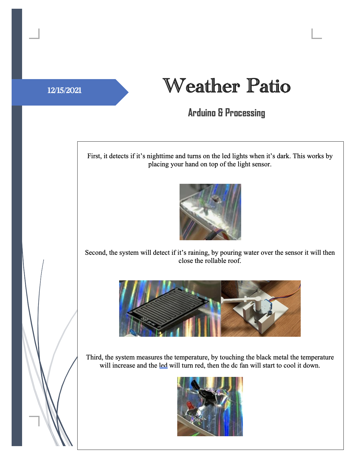
The project is a smart outdoor cover that we called the weather patio . It has the following different features. First, the system will detect if it’s raining, and if it is then it will close the rollable roof. Second, the system measures the temperature and if the temperature is very high, it will turn on a fan. Last, but not least, it detects if it’s night time and turns on the lights when it’s dark.
SYSTEM I/O:
Input:

- Rain Sensor

- Temperature Sensor

- Light Sensor
Output:

-Servo or DC Motor

-Fan DC

-LED Strip with relay
DESCRIPTION OF EACH INPUT/OUTPUT ON ARDUINO & WHAT IT WILL SEND/RECEIVE FROM PROCESSING :
Input Arduino:
-
-
-
-
Rain sensor to detect if it’s raining
-
Temperature sensor to detect the ambient temperature.
-
Light sensor to detect the light in the area.
-
-
-
Output Arduino:
-
-
-
-
Motor (servo or DC) to close and open the roof top
-
Fan to cool down the temperature
-
LED strip or bulb to add light during the night
-
-
-
Basically, all the inputs will send the data to the processing in order to be visualized on the processing screen. That allows monitoring of the temperature, rain existence and light in the area. Thus, all the outputs of the Arduino will receive control from the processing , as the system we are building is automatic using the Arduino code with processing code integrated.
DESCRIPTION OF PROCESSING & WHAT IT WILL SEND/RECEIVE TO ARDUINO:
Processing is used for one main reasons:
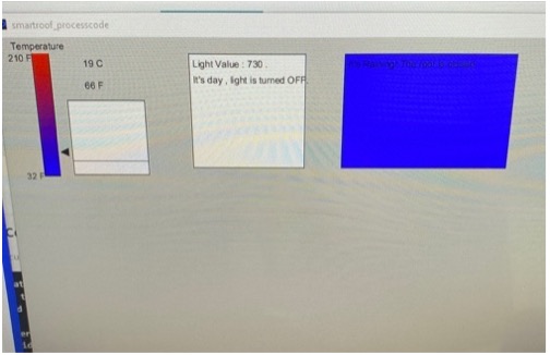
- Monitor the values given by the temperature sensor and other sensors. Provides interactive visualizations of the output in order to capture the essence of the experience.
PROCEDURE:
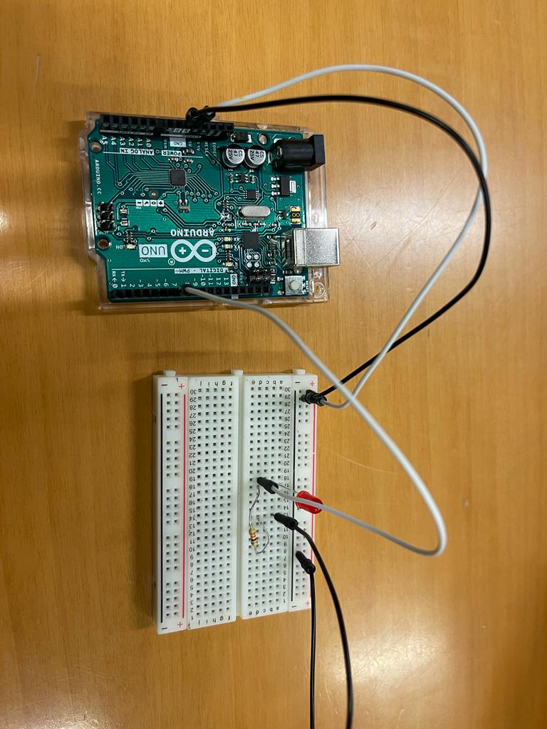
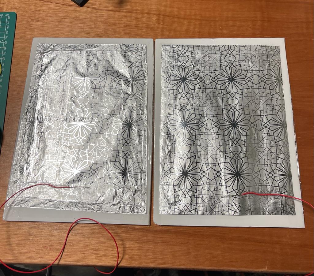
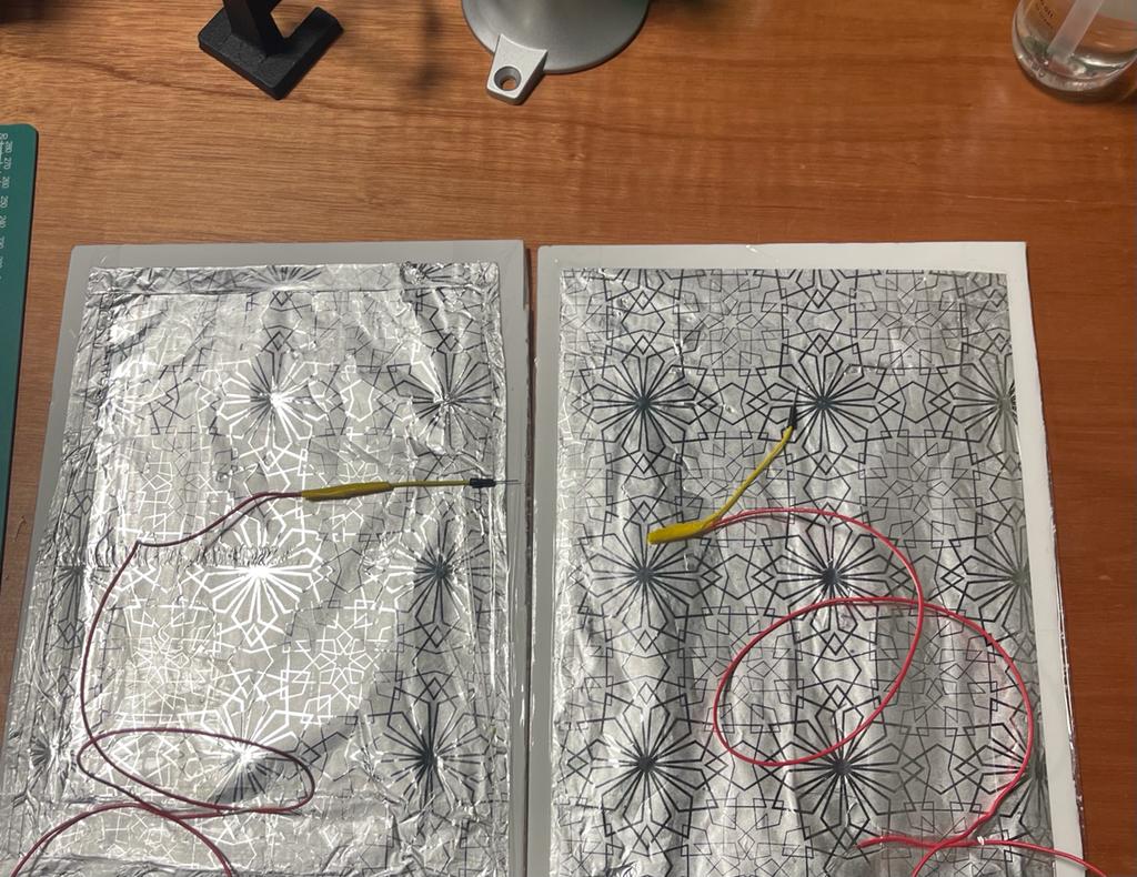
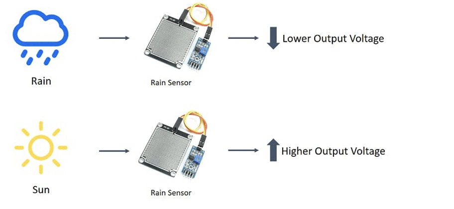
RAIN FALL SENSOR:
The rain sensor detects water that comes short circuiting the tape of the printed circuits.

The sensor acts as a variable resistance that will change status : the resistance increases when the sensor is wet and the resistance is lower when the sensor is dry.
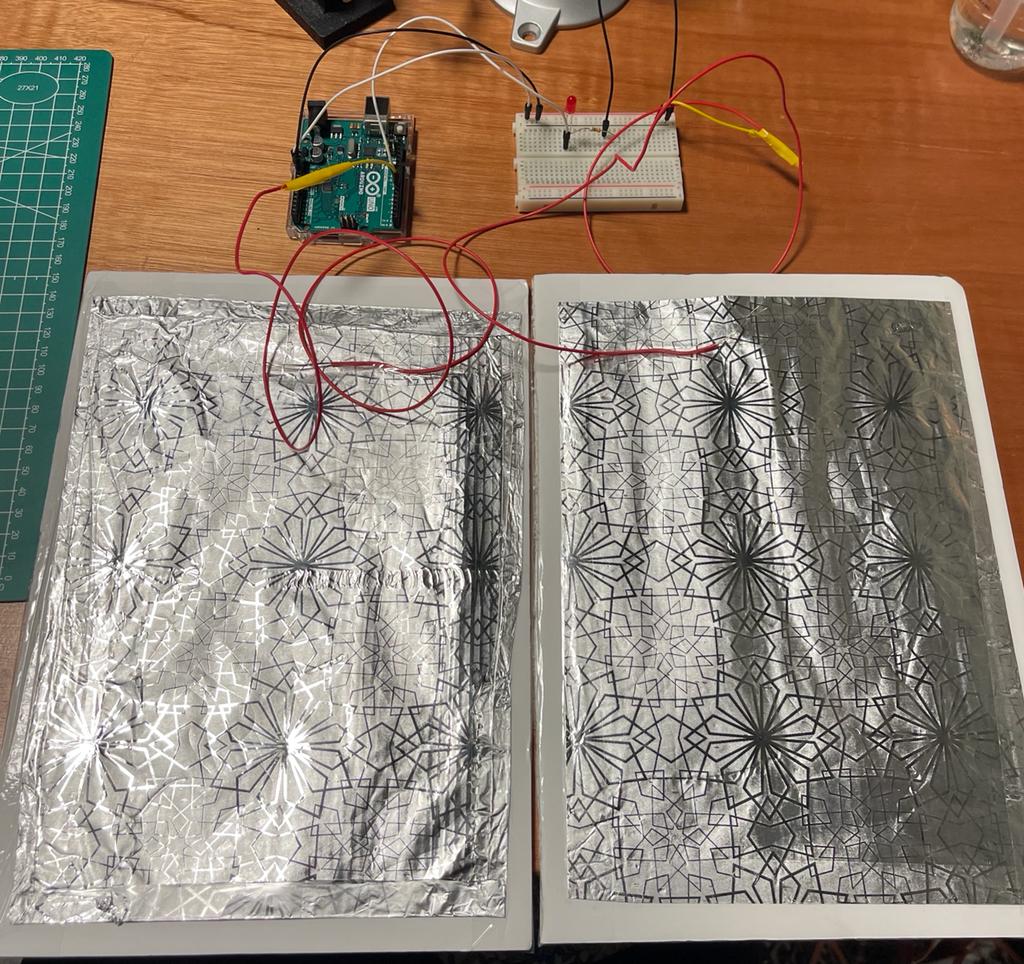
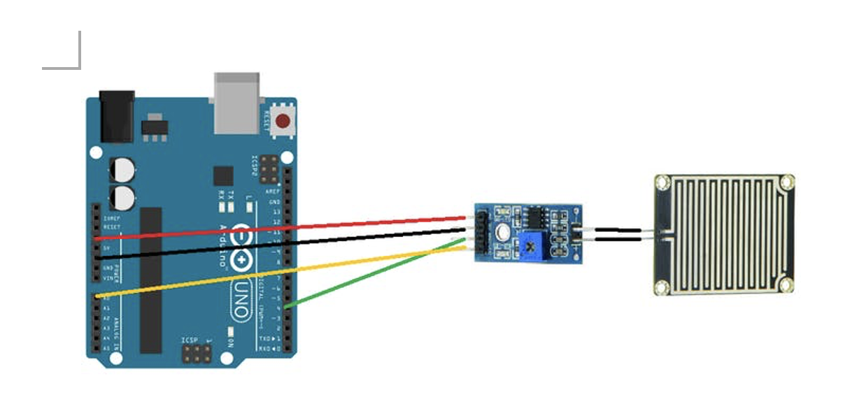
Connection:
Arduino –> Comparator
5V –> VCC
GND –> GND
DO –> D4
AO –> A0
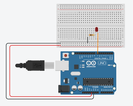
Blueled ->pin 3
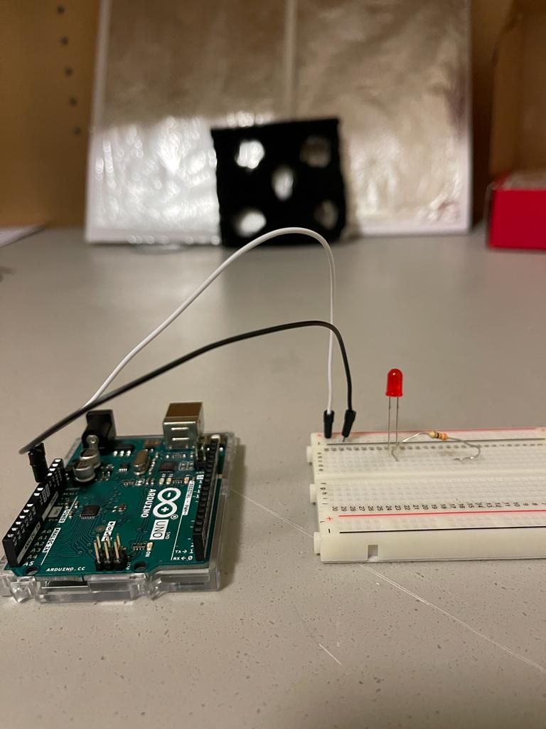
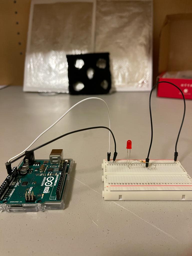
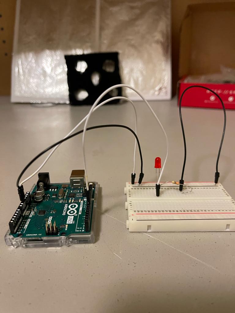
A blue LED is connected to show the presence of rain. If it’s raining, the blue LED will turn on, if it’s not raining the blue LED is off.
Code of Rain Sensor :
//RAINFALL SENSOR CODE
const int capteur_D = 4;
const int capteur_A = A0;
int blueled=2;
int val_analogique;
void setup()
{
pinMode(capteur_D, INPUT);
pinMode(capteur_A, INPUT);
pinMode(blueled, OUTPUT);
Serial.begin(9600);
}
void loop()
{
if(digitalRead(capteur_D) == LOW)
{
Serial.println("Digital value : wet");
delay(10);
digitalWrite(blueled,HIGH);
}
else
{
Serial.println("Digital value : dry");
delay(10);
digitalWrite(blueled,LOW);
}
val_analogique=analogRead(capteur_A);
Serial.print("Analog value : ");
Serial.println(val_analogique);
Serial.println("");
delay(1000);
}
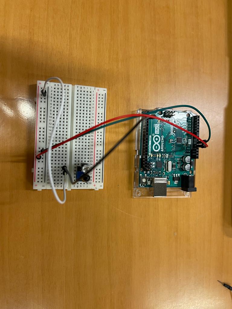
LIGHT SENSOR:
LDR light dependent resistor to have an automatic light turn on when it’s dark.
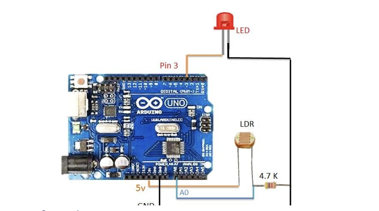
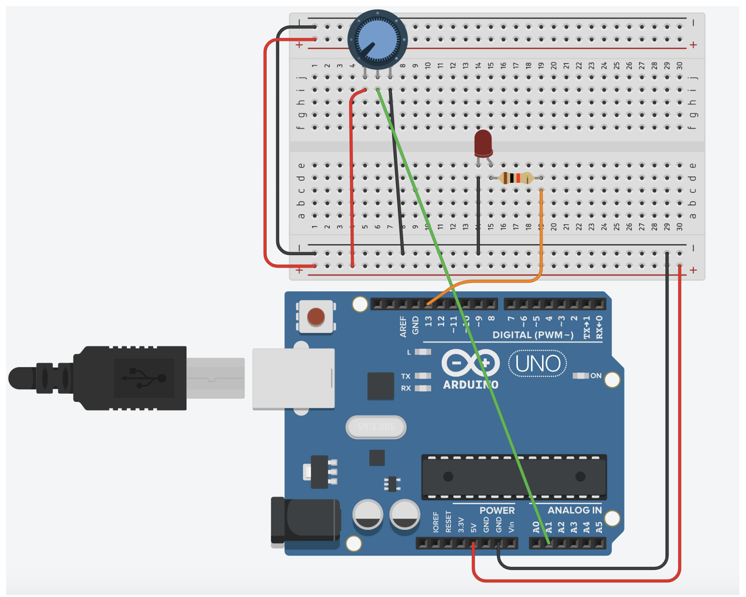
Connection
LDR: one side to 5V, other pin to analog pin A1 and to a 4.7K resistor connected to GND.

Output: LED on pin 3
Code with LDR:
const int capteur_D = 4;
const int capteur_A = A0;
int blueled=2;//for rain
int val_analogique;
int LDRsensorPin=A1;
int LDRsensorValue = 0;
int greenled = 3;//green light for ldr
void setup()
{
pinMode(capteur_D, INPUT);
pinMode(capteur_A, INPUT);
pinMode(blueled, OUTPUT);
pinMode(greenled, OUTPUT);
Serial.begin(9600);
}

void loop()
{
if(digitalRead(capteur_D) == LOW)
{
Serial.println("Digital value : wet");
delay(10);
digitalWrite(blueled,HIGH);
}
else
{
Serial.println("Digital value : dry");
delay(10);
digitalWrite(blueled,LOW);
}
val_analogique=analogRead(capteur_A);
Serial.print("Analog value : ");
Serial.println(val_analogique);
Serial.println("");
LDRsensorValue = analogRead(LDRsensorPin);
if(LDRsensorValue < 600)
{
Serial.println("LED light on");
digitalWrite(greenled,HIGH);Serial.println(LDRsensorValue);
//delay(1000);
}
else {digitalWrite(greenled,LOW);Serial.println(LDRsensorValue);}
delay(1000);
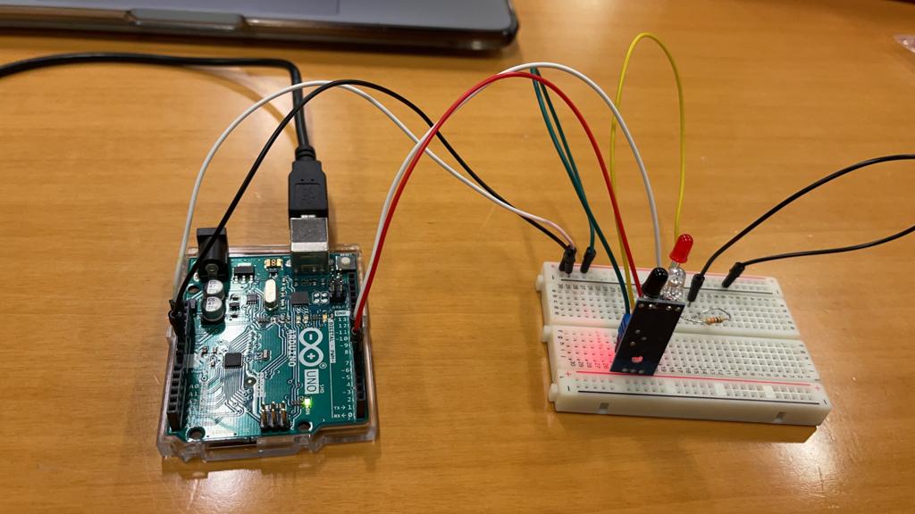
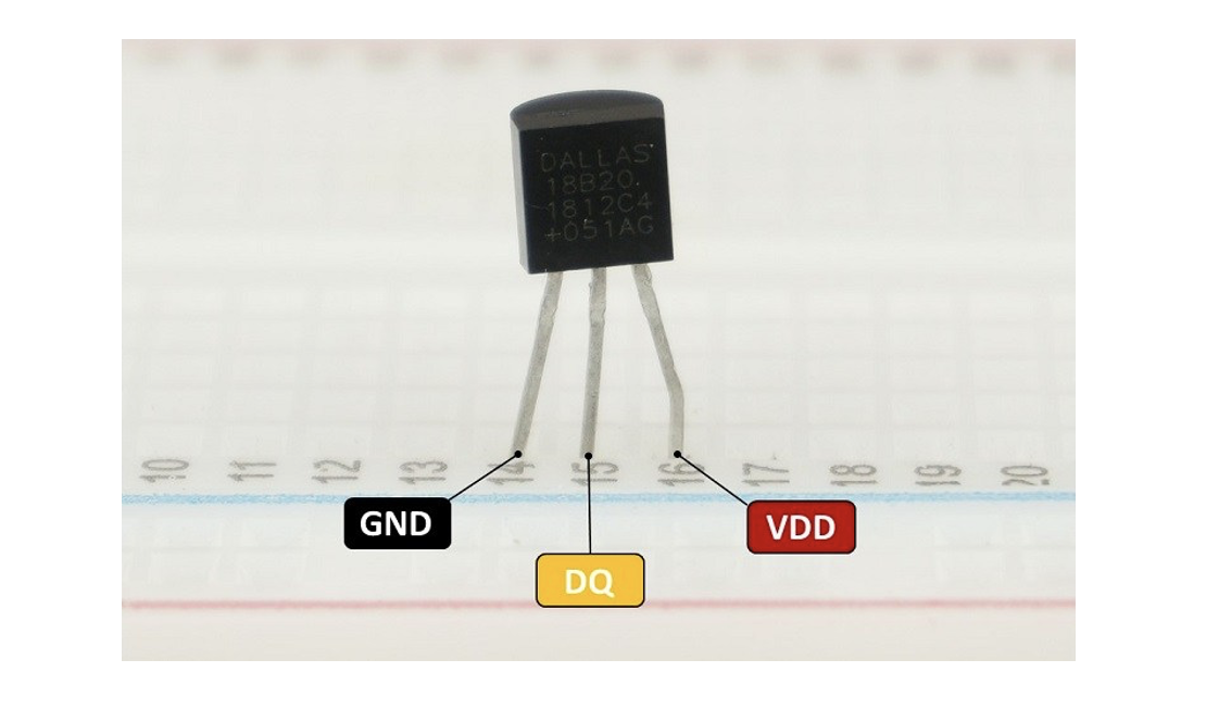
TEMPERATURE SENSOR & FAN:
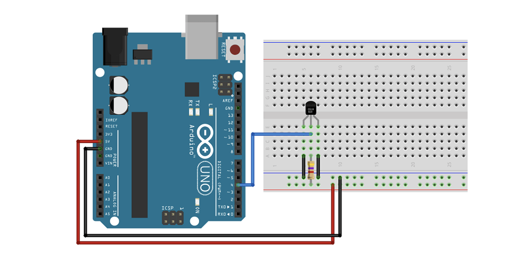
We need a temperature sensor DS18B20 with a 4.7kohm resistor for input, as output we have a dc fan.

           If the temperature is high the fan will turn on.

           If the temperature is low the fan is off.
           Digital pin used is pin 5 for the temperature sensor

           Red led is to show if the temp above the limit.

           Redled is on pin 6
Code :
//code for temperature sensor
#include <OneWire.h>
#include <DallasTemperature.h>
#define ONE_WIRE_BUS temppin //pin in 4
OneWire oneWire(ONE_WIRE_BUS);
DallasTemperature sensors(&oneWire);
void setup()
{
pinMode(redled, OUTPUT);
Serial.begin(9600);
//code for tempqrature
sensors.begin();
}
void loop()
{
/********************************************************************/
//temperature sensor
sensors.requestTemperatures(); // Send the command to get temperature readings
Serial.println("Temperature is: ");
celsius = sensors.getTempCByIndex(0);
Serial.print(celsius);
if(celsius>baselinetemp)digitalWrite(redled,HIGH);
else digitalWrite(redled,LOW);
}
STEPPER MOTOR :
The stepper motor used is a 5 V motor with a Stepper Motor with Driver (28BYJ-48 5V DC).
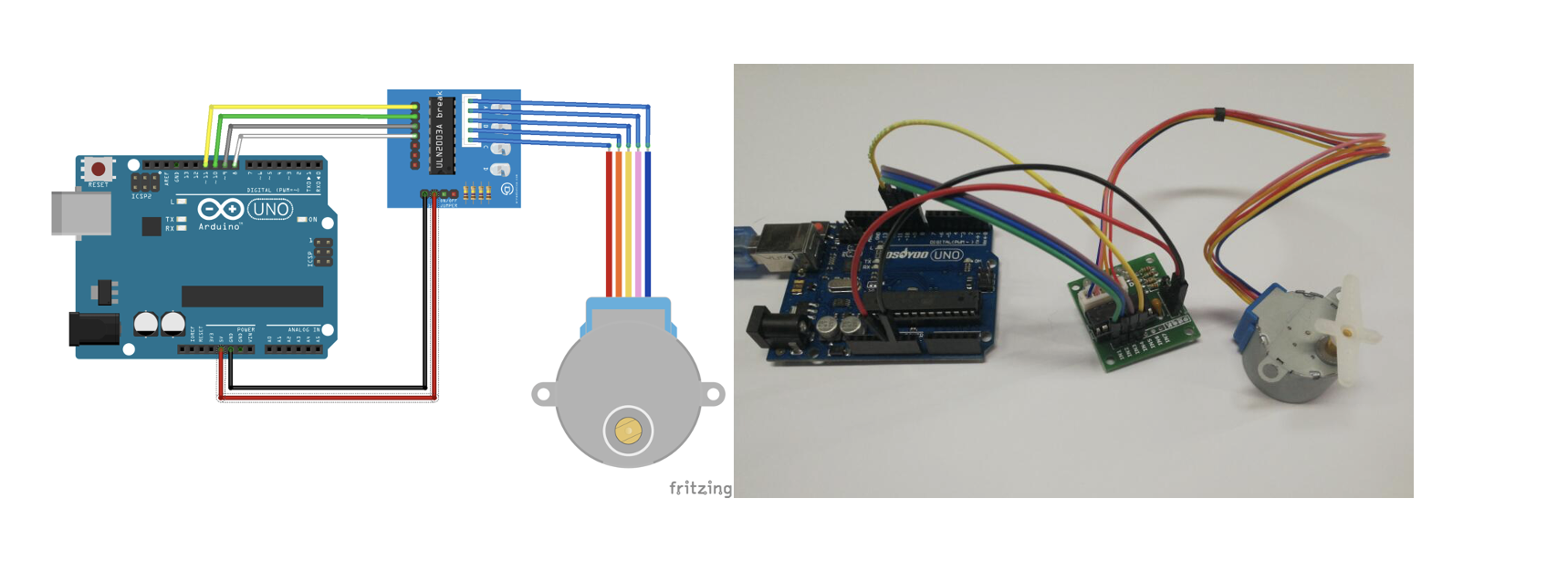
A stepper motor, much like a DC motor has a rotating permanent magnet propelled by stationary electrical magnets, however the motion is divided into a number of steps around the rotation of the rotating magnet. It does so by having several teeth on the rotating magnet that line up with specific locations around the stationary charged magnets. When voltage is supplied to a specific magnet or specific sequence of magnets the motor will rotate, or step to that position and hold.

Stepper motors can spin like a regular DC motor, however they can also stop on a position like a servo motor.
Code is using the library Stepper.h :
#include <Stepper.h>
// Define number of steps per rotation:
const int stepsPerRevolution = 2048;
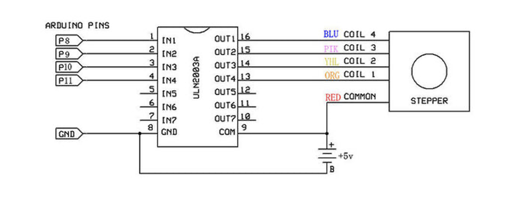
// Wiring:
// Pin 8 to IN1 on the ULN2003 driver
// Pin 9 to IN2 on the ULN2003 driver
// Pin 10 to IN3 on the ULN2003 driver
// Pin 11 to IN4 on the ULN2003 driver
// Create stepper object called 'myStepper', note the pin order:
Stepper myStepper = Stepper(stepsPerRevolution, 8, 10, 9, 11);
void setup() {
// Set the speed to 5 rpm:
myStepper.setSpeed(5);
// Begin Serial communication at a baud rate of 9600:
Serial.begin(9600);
}
void loop() {
// Step one revolution in one direction:
Serial.println("clockwise");
myStepper.step(stepsPerRevolution);
delay(500);
// Step one revolution in the other direction:
Serial.println("counterclockwise");
myStepper.step(-stepsPerRevolution);
delay(500);
}
Code Explanation:
The Stepper.h Arduino library is included in the first step of the project. On the website, you may learn more about this library.
// Include the Arduino Stepper.h library:
#include <Stepper.h>
Then we estimated how many steps it takes the motor to complete one rotation. We'll use the motor in full-step mode in this example. This translates to 2048 steps to complete a 360-degree rotation (see motor specifications above).
// Define number of steps per rotation:
const int stepsPerRevolution = 2048;
The next step is to build a new instance of the Stepper class, which represents a specific stepper motor that is attached to the Arduino. The function Stepper(steps, pin1, pin2, pin3, pin4) is used for this, where steps is the number of steps per revolution and pin1 through pin4 are the motor's pins. Set the pins in the following order to acquire the right step sequence: 8, 10,9,11.
// Create stepper object called 'myStepper', note the pin order:
Stepper myStepper = Stepper(stepsPerRevolution, 8, 10, 9, 11);
We labeled the stepper motor 'myStepper' in this example, but you could call it 'z motor' or 'liftmotor' instead. For example ,
Stepper liftmotor = Stepper(stepsPerRevolution, 8, 10, 9, 11);
Multiple stepper motor objects with distinct names and pins can be created. This makes it simple to control two or more stepper motors at once.

With the function, you may specify the speed in rpm in the setup by having
setSpeed(rpm).
At 5 V, a 28byj-48 stepper motor's maximum speed is around 10-15 rpm.
void setup() {
// Set the speed to 5 rpm:
myStepper.setSpeed(5);
// Begin Serial communication at a baud rate of 9600:
Serial.begin(9600);
}
We just call the step(steps) function in the loop part of code, which rotates the motor a certain number of steps at a speed defined by the function below
setSpeed(rpm)
Passing a negative value to this function causes the motor to spin in the opposite direction.
void loop() {
// Step one revolution in one direction:
Serial.println("clockwise");
myStepper.step(stepsPerRevolution);
delay(500);
// Step one revolution in the other direction:
Serial.println("counterclockwise");
myStepper.step(-stepsPerRevolution);
delay(500);
}
Source Used :
28byj-48-stepper-motor-arduino-tutorial
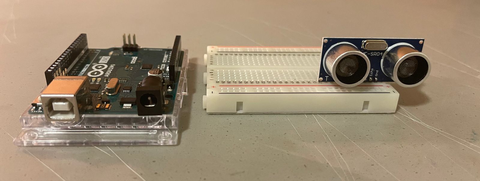
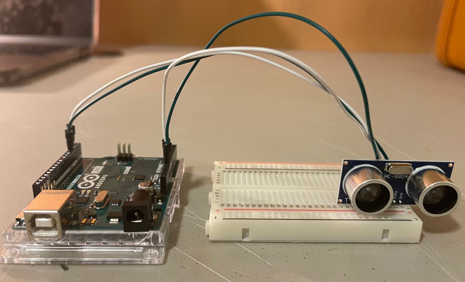
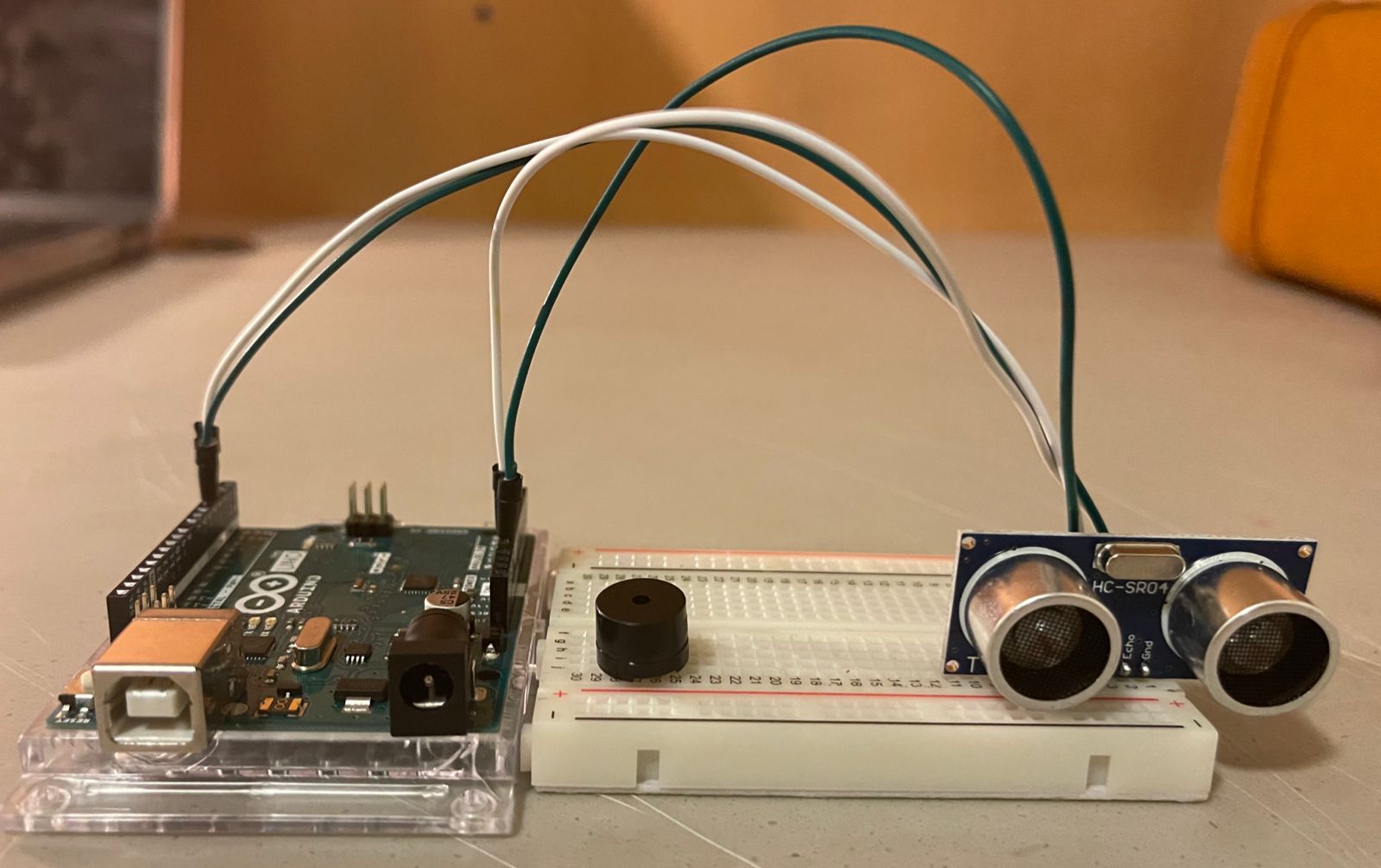
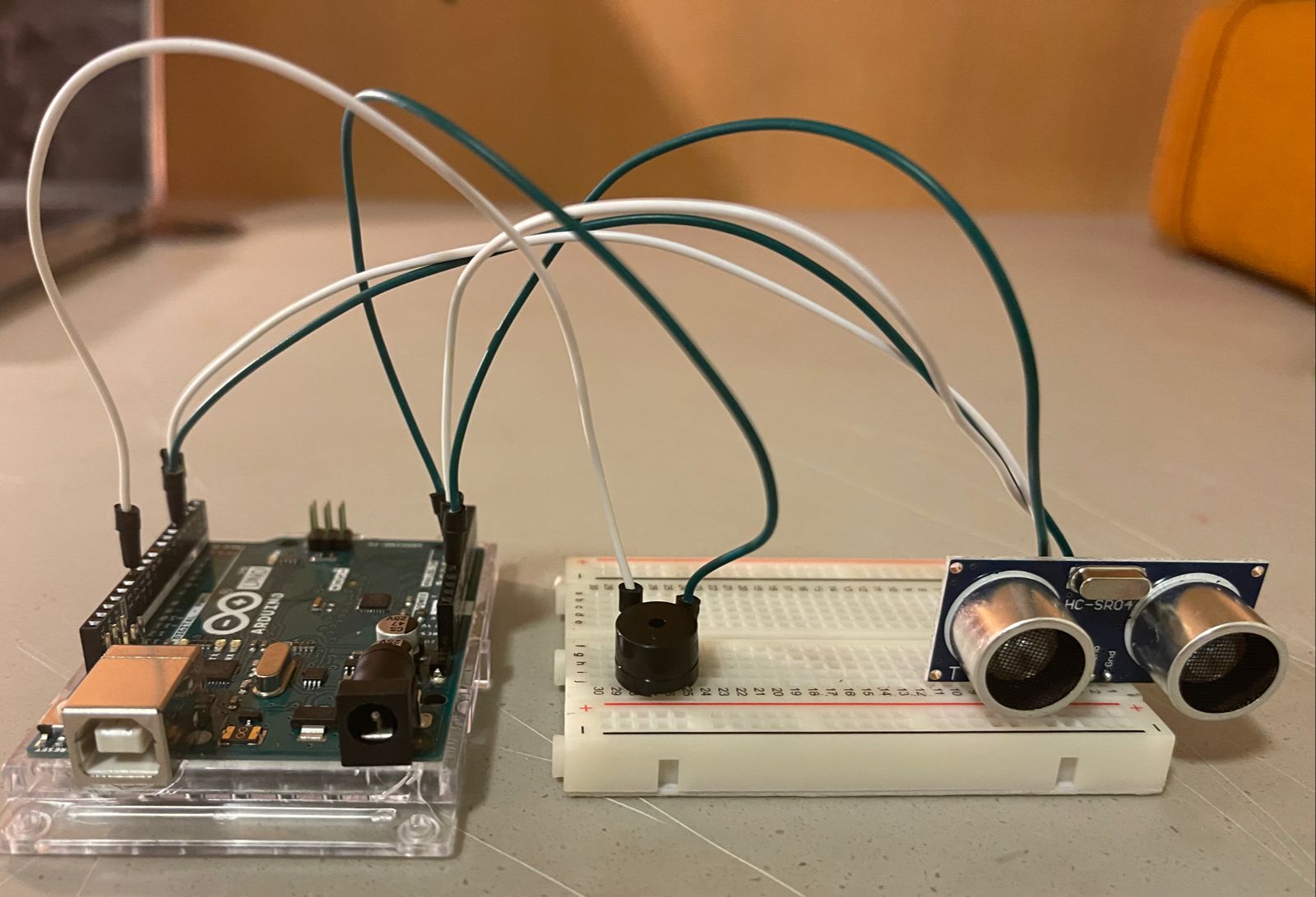
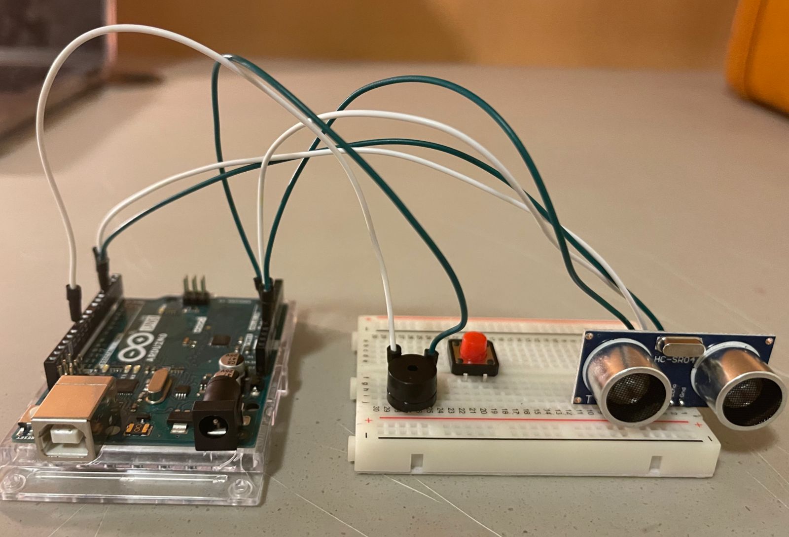
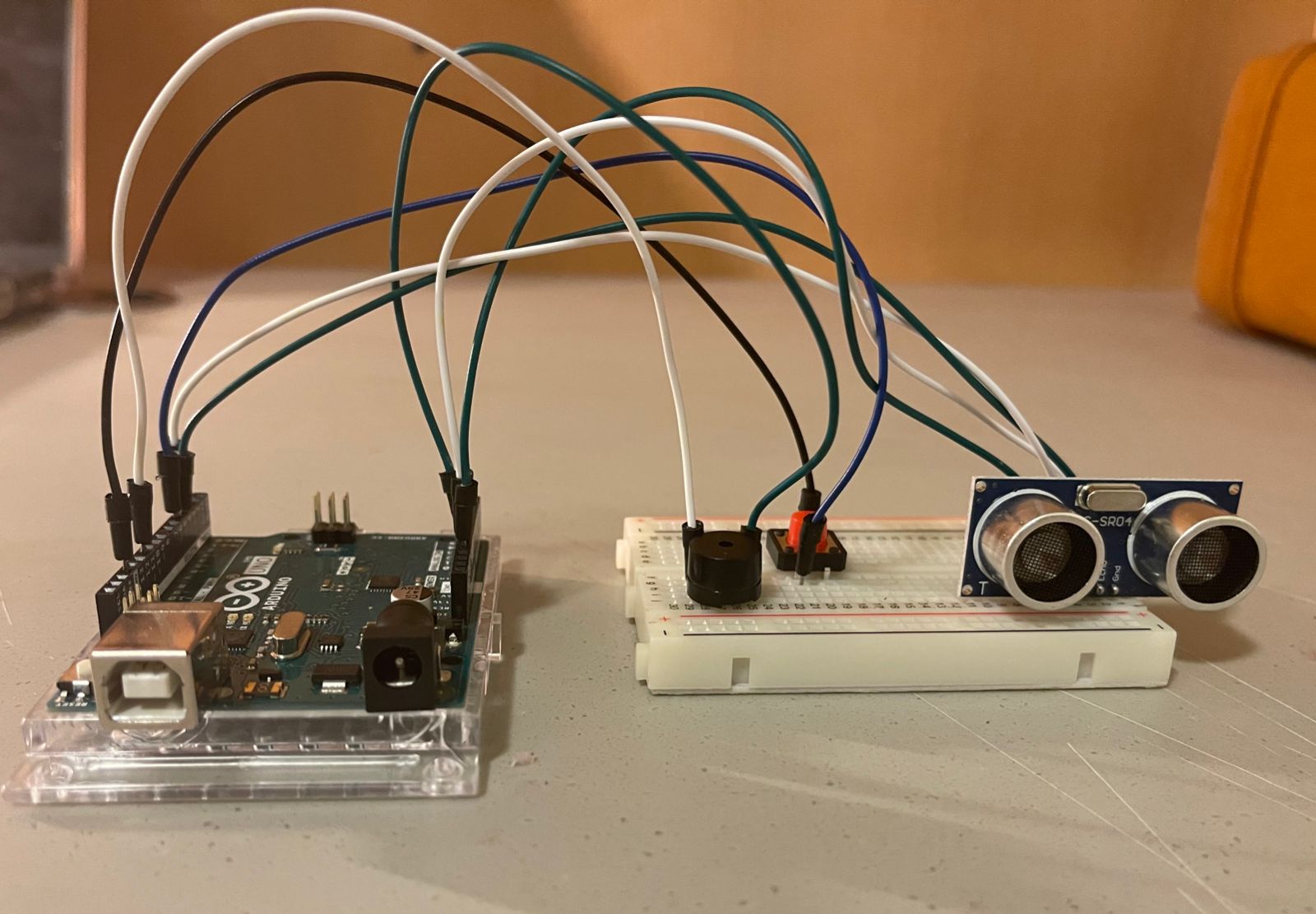
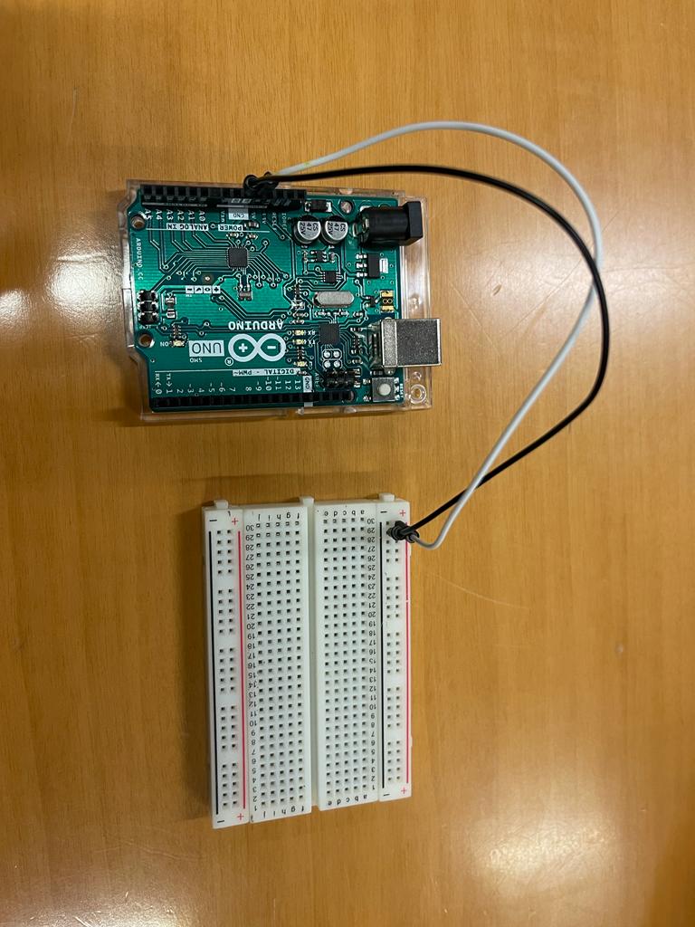
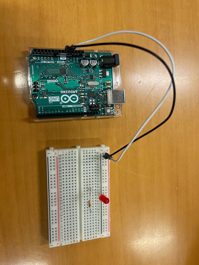
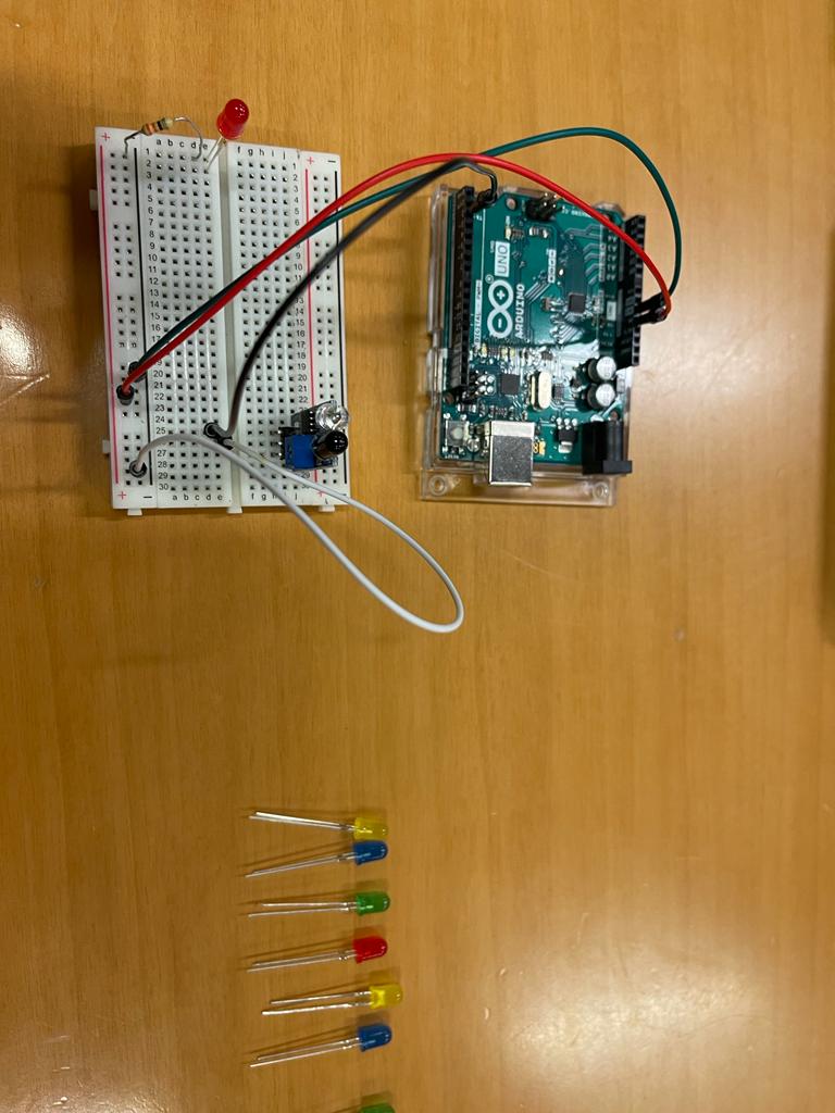
ASSEMBLY:
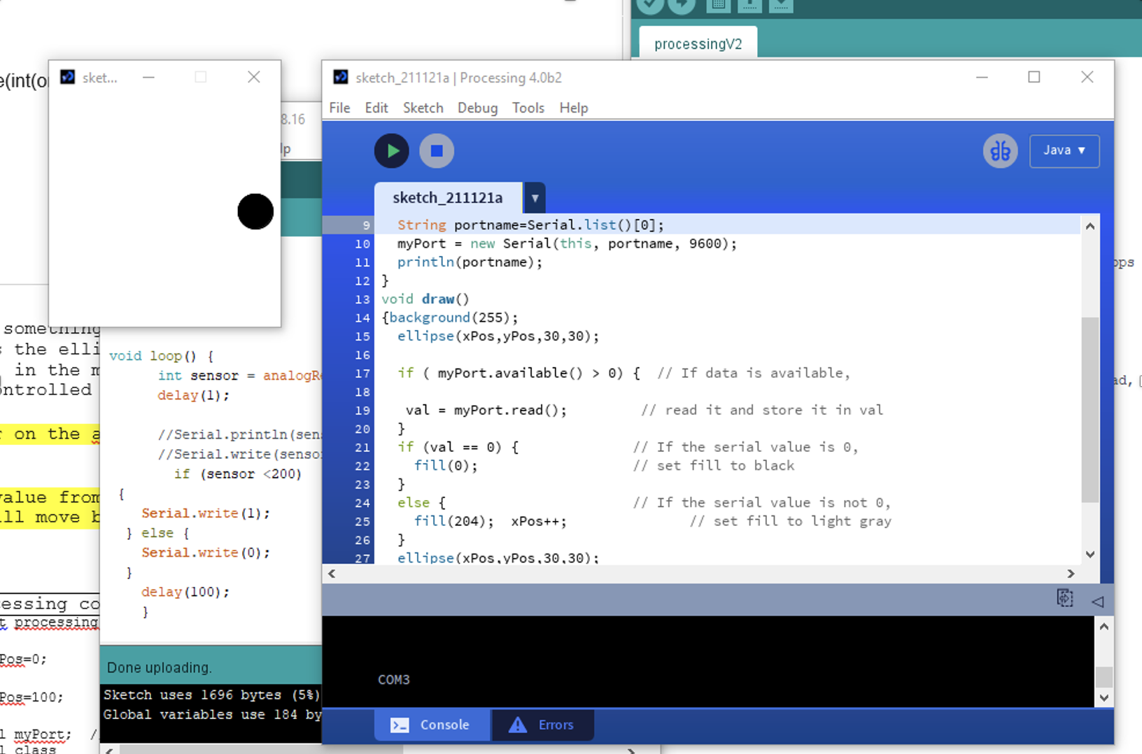
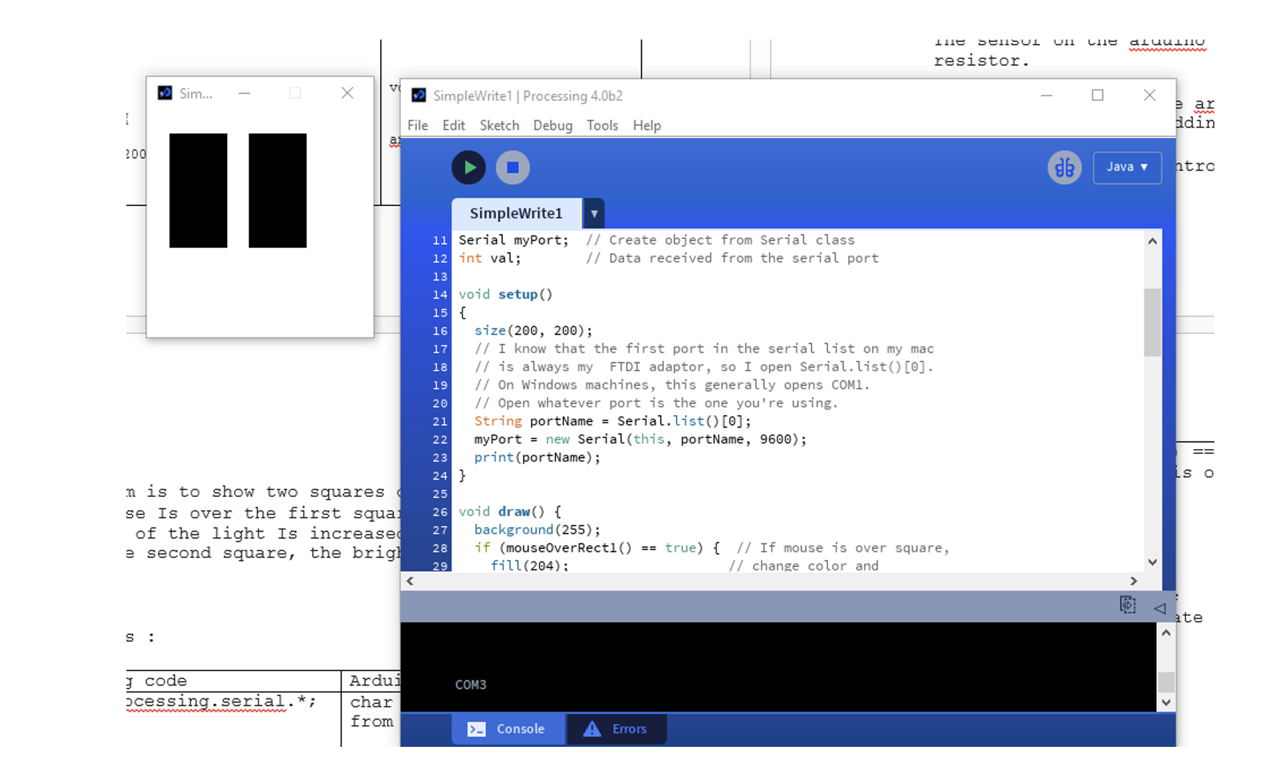
After having each sensor as input and component as outputs, we put everything together to assemble the project. For the processing code we based our code on the professors code :
In order to send multiple values from the Arduino to processing, we kept the handshake and we read the values.
CONNECTION:
The stepper Motor is connected to the cover that should close when it rains. In order to have the motor control the cover we assumed the cover has a roller controller like the one found in normal curtains. So, we designed the controller that could be fitted into the stepper motor and to the cable of the roller curtain. Once the stepper motor turns clockwise, it will close the cover and if it turns anti clockwise it will open the cover
The reference to have the piece for the roller curtain is on this tutorial found below ...
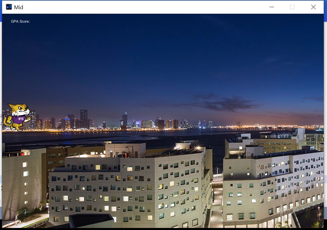
PROCESSING PROCEDURE :
After getting feedback from the professor, we changed the processing code entirely to have a more interactive animation. The code changed the display from a value display to an interactive animation display. In order to do the new code we used snippets of code from the open processing website.
The 4 screen parts are:

- Sun

- Moon

- Rain

- Thermometer
Below are the Code for Each Part:
int nb=750; // number of drops
int maxDrops =1000;
int minDrops=500;
int h,h1;
Drop[] drops=new Drop[maxDrops];

void setup(){
  size(900,625,P3D);
  smooth();
  frameRate(30);
  h = abs(height/3);
  h1=h*2;
  for (int i = 0; i < maxDrops; i++){
    drops[i] = new Drop(int(random(width)),-int(random(height*2)),(int)map((h+int(random(h1))),height*.35,height,0,height),1280);
  }

}

void draw(){
  gradient();
  for (int i=0;i<nb;i++){
    drops[i].fall();
  }
}

void gradient(){
  noStroke();
  beginShape(QUADS);
  fill(188,190,192);
  vertex(0,0);
  vertex(width,0);
  fill(0,5,10);
  vertex(width,height);
  vertex(0,height);
  endShape();
}

class Drop{
  int x,y,d,z,onde,d1,oldY;
  float acc;
  boolean s;

  Drop(int x,int y, int z, int d){
    this.x=x;
    this.y=y;
    this.d=d;
    this.z=z;
    onde=0;
    d1=d;
    acc=0;
    oldY=y;
  }

  void fall(){
    if(y>0)acc+=0.2;
    stroke(200,200,200,map(z,0,height,0,255));
    strokeWeight(2);
    if (y<z){
      y=int(y+4+acc);
      line(x,oldY,x,y);
      oldY=y;
    }
    else{
      noFill();
      stroke(175,175,175,175-map(onde,0,d,0,255));
      strokeWeight(map(onde,0,d,0,4));
      d=d1+(y-height)*4;
      ellipse(x,y,onde/5,onde/20);
      onde=onde+7;
      if(onde>d){
        onde=0;
        acc=0;
        x=int(random(width));
        y=-int(random(height*2));
        oldY=y;
        d=d1;
      }
    }
  }
}
void setup() {
    size( 600, 600 );
    smooth();
}

void draw() {

    background( 51 ); //resents background color to dark gray
    int rbound = 200; //default

    fill( 255, 246, 64 ); //yellow
    stroke( 255, 246, 64 ); //yellow
    strokeWeight( 5 );
    int twinkle = 80; //distance change in ray length
    //float radius=200; //radius of rays
    float radius;
    int numPoints=130; //number of rays
    float angle=TWO_PI/(float)numPoints;

    //create rays
    for(int i=0;i<numPoints;i++)
    {
        radius = rbound - (int)random( 0, twinkle );
        line(300,300,radius*sin(angle*i)+300,radius*cos(angle*i)+300);
    }

    //ellipse( 300, 300, 200, 200 ); //sun

    //face
    stroke( 51 ); //dark gray
    strokeWeight( 4 );

        arc( 250, 300, 40, 30, PI, TWO_PI ); //left eye
        arc( 350, 300, 40, 30, PI, TWO_PI ); //right eye
    arc( 300, 335, 100, 70, PI/6, 5*PI/6 ); //mouth

}
float phaseNum=2;
int index = 0;
PFont f;

void setup() {
  size(500,500);
  background(0);
  noStroke();
}

void draw(){
  fill(0,random(170,200));
  rect(0,0,width,height);
  drawMoon();
  {drawShadow((width/2)-(phaseNum*35),height/2);}
}


void drawMoon(){
    for(int i=1; i<50; i++) {
      fill(245,10);
      ellipse(width/2, height/2,200-i*5,200-i*5);
      ellipse(width/2, height/2,150,150);
    }
}

void drawShadow(float x, float y) {
    for(int i=1; i<50; i++) {
      fill(0,80);
      ellipse(x, y,180-i*5,180-i*5);
    }
}
Challenges faced :
The challenges faced are mostly the changes that we had to do for the processing code. As we first wrote a code that displays the values of the sensors, then after the feedback, we changed the code into animation which is interactive with the sensor output. So glad we did that as it made our project come all together. The project was a learning curve as we spent a lot of time working on the mechanism of the moveable roof, and on the processing code to display the interactive animation.
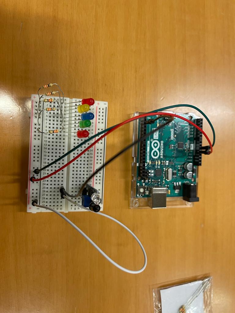
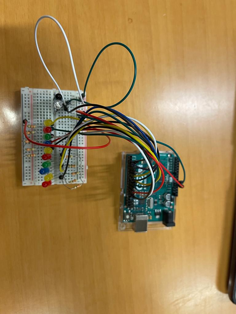
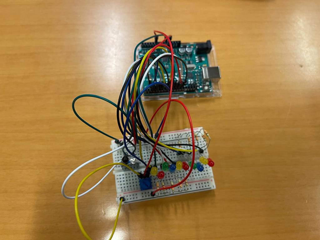
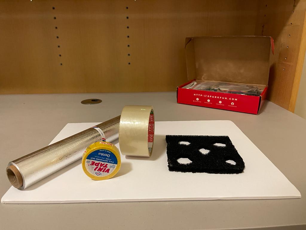
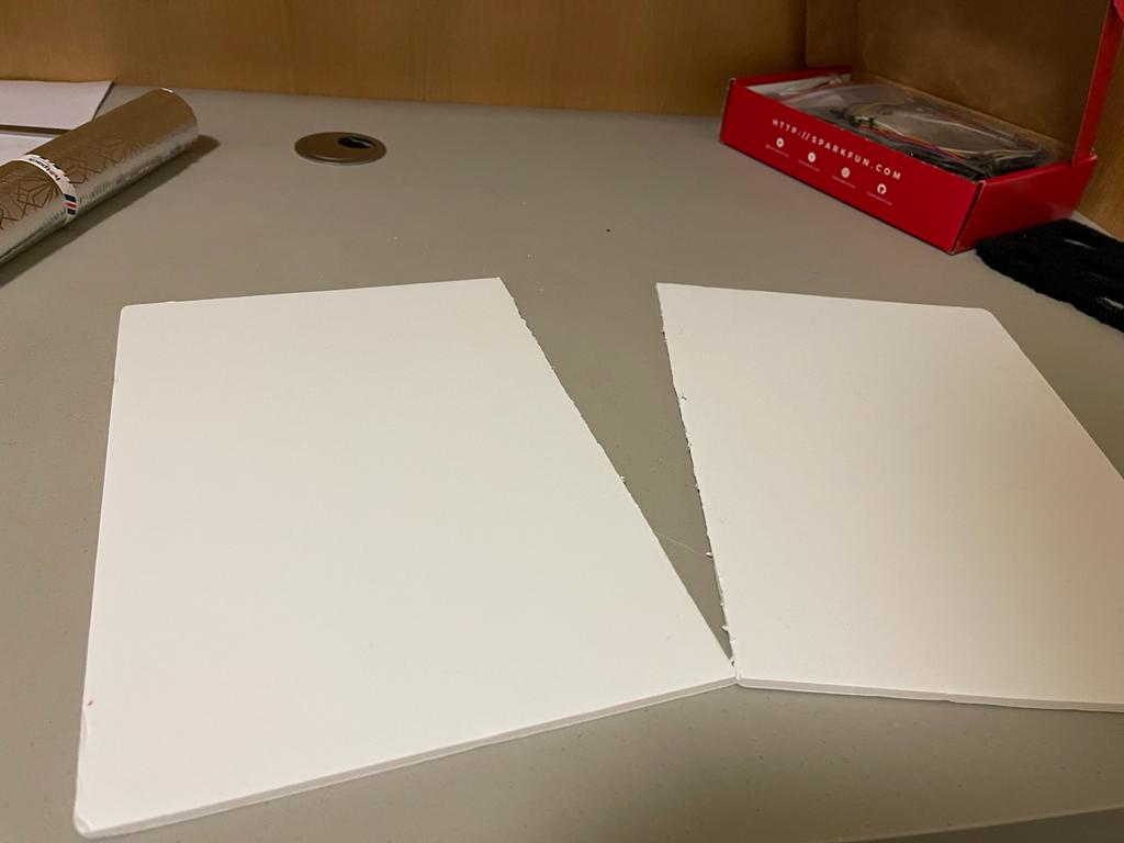
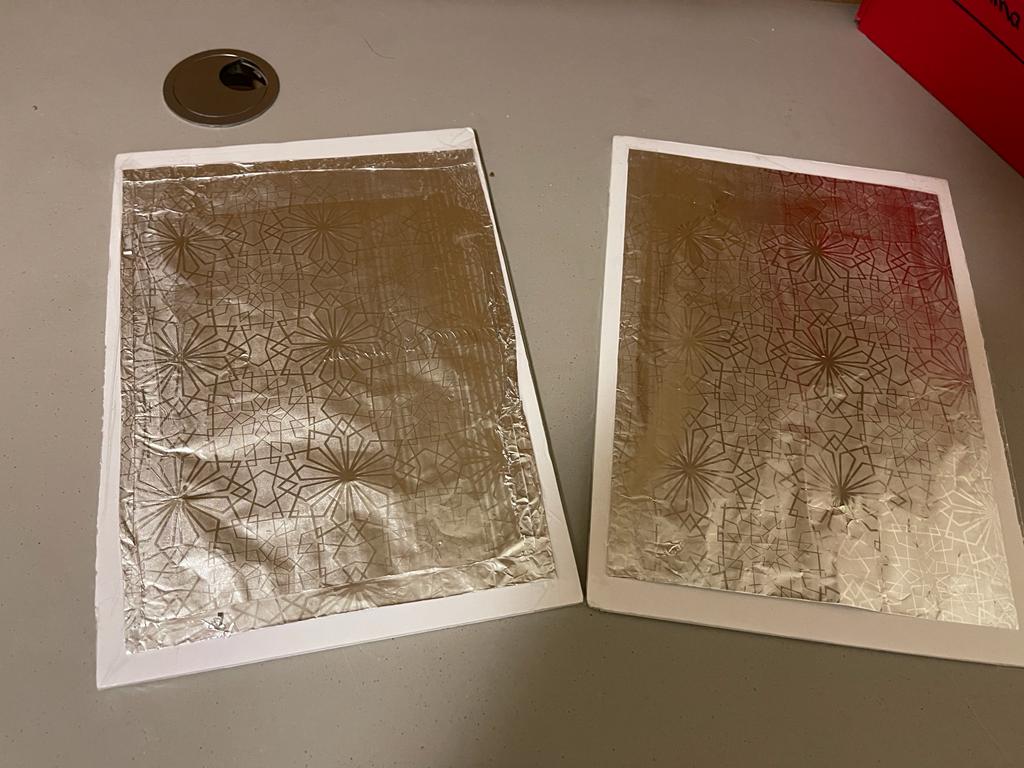
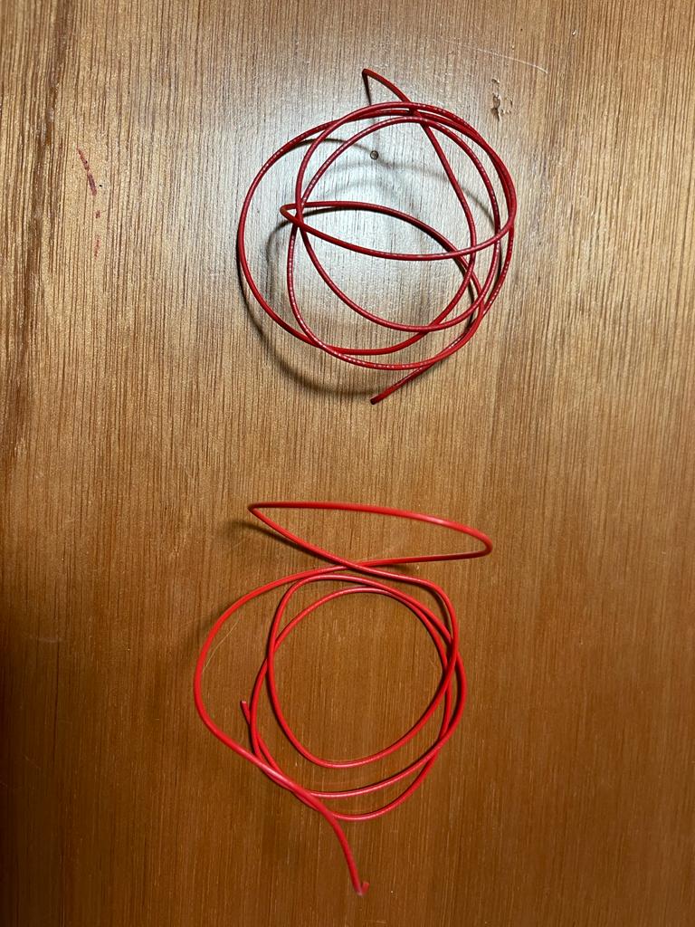
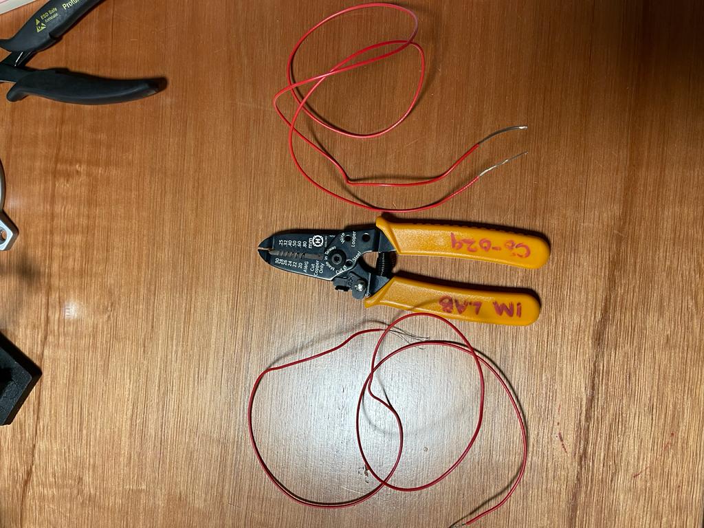
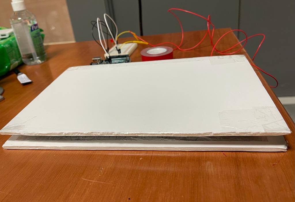
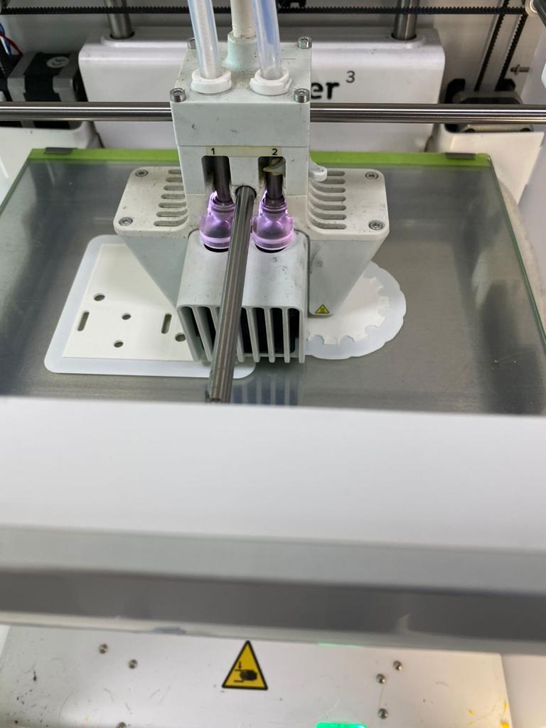
IMAGES OF OUR PROCEDURE :
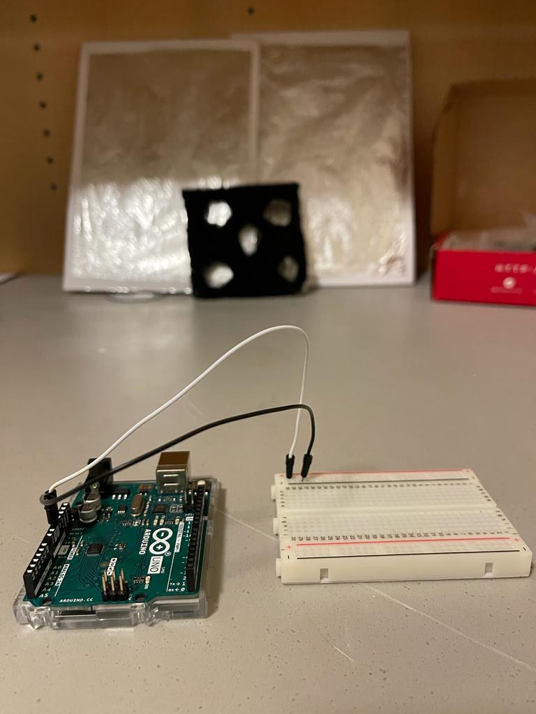
The 3D printer that we used to print the pieces we made
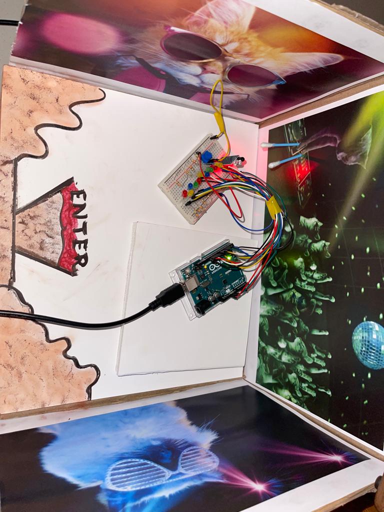
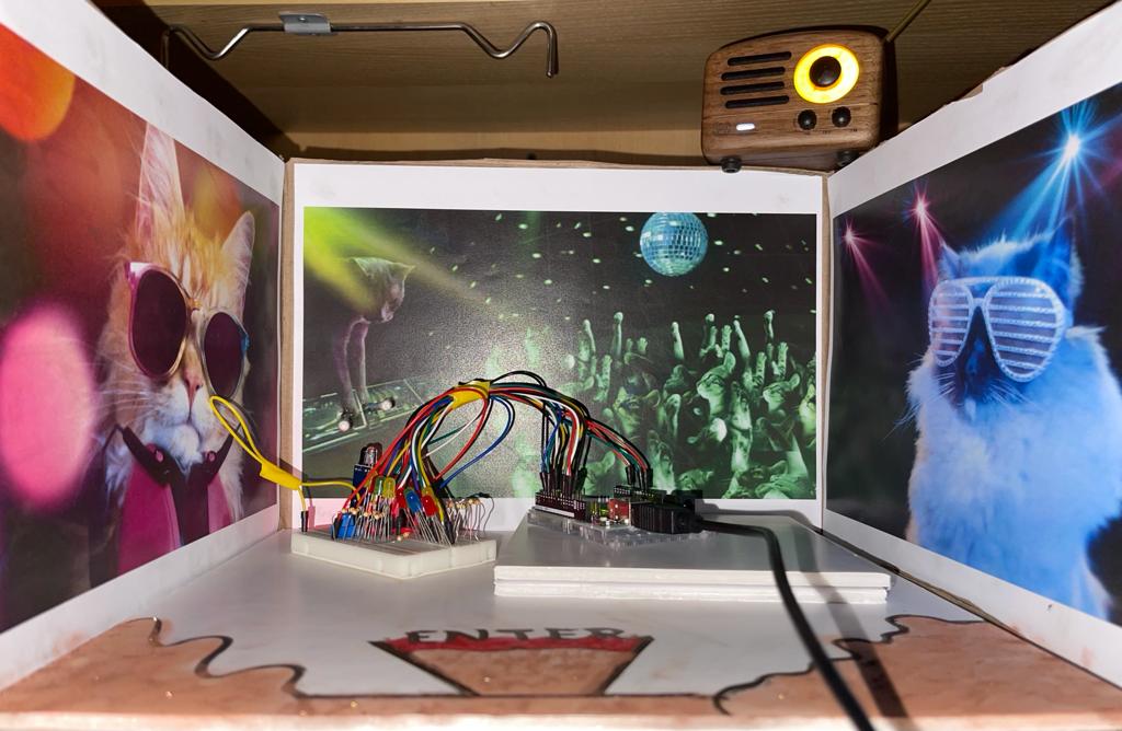
The journey of making our brainstorming session come into reality by putting the hardware of Arduino to processing connection.
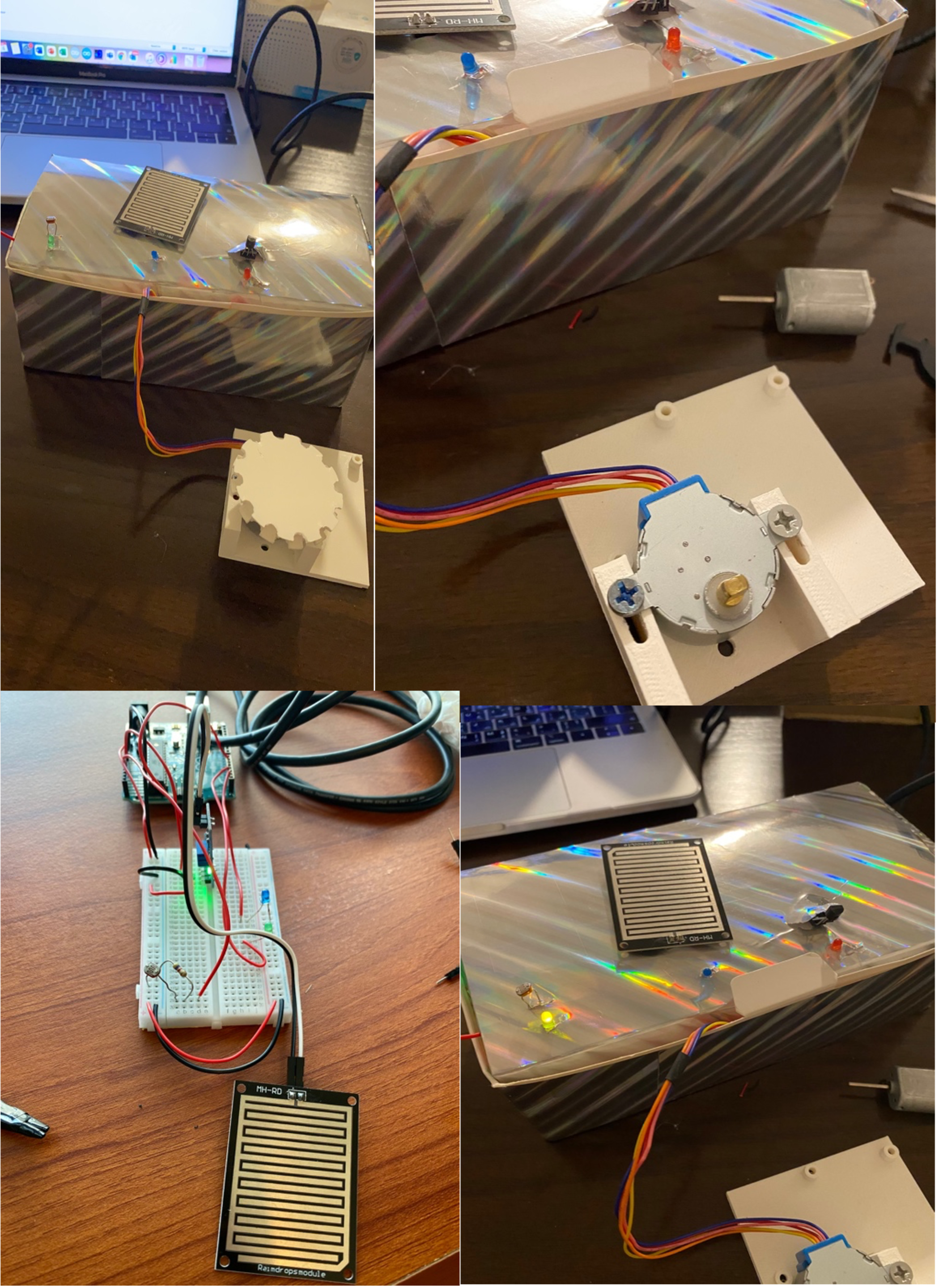
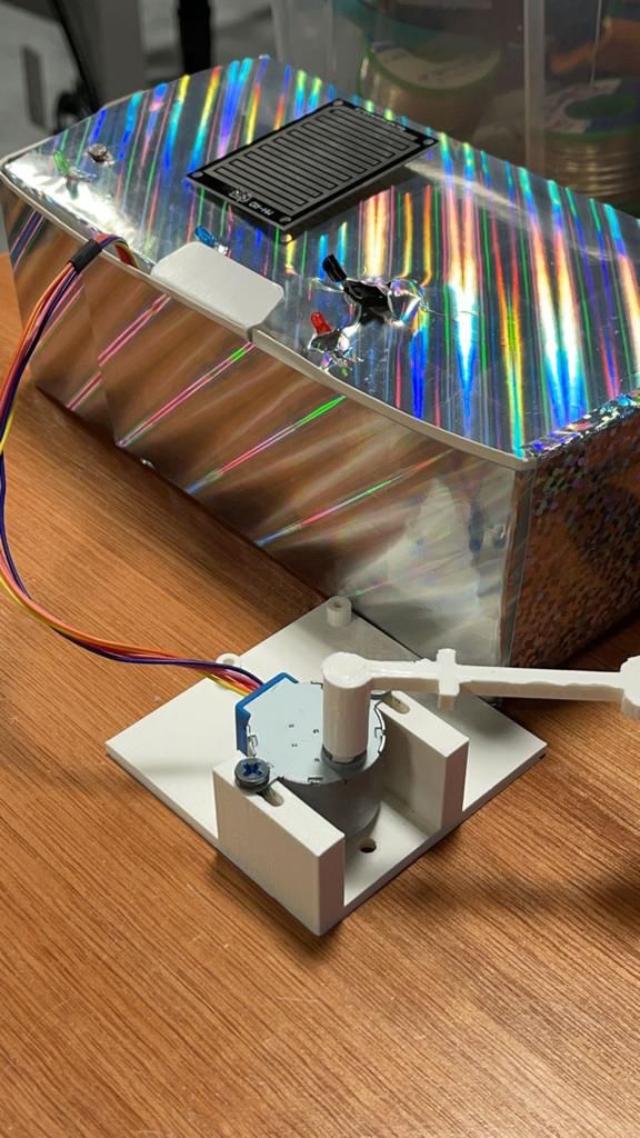
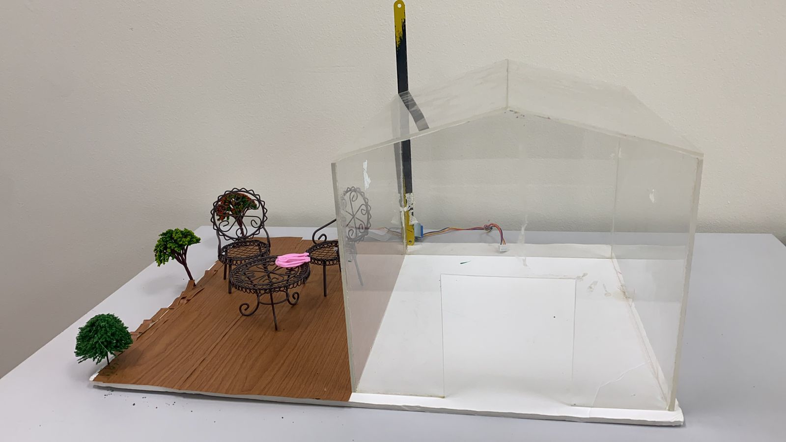
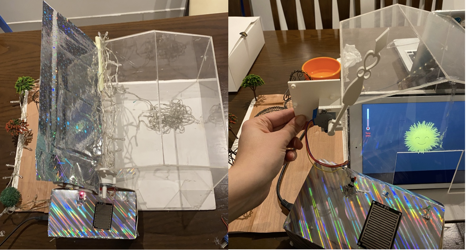
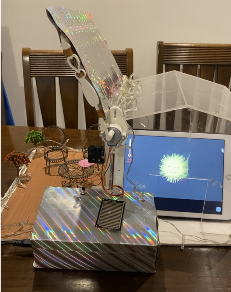
In the above image, we only 3D printed a different piece that would be for our roof just cause we though it would look more aesthetic and is more practical when putting it together.

Later, we designed the house out of plexi, on which we attached a motor. Then we connected the motor to a lever which is the white part and that lifts the roof. Through coding in Arduino, we can rotate the roof in terms if lifting and lowering. Another thing is that we attached a fan to the house to be used with the temperature sensor. The control box found is where we kept all the sensors. In addition, we added a double relay connected to the led strip and the fan to control them, as these components require a higher voltage power. The final prototype looks like a house with a moveable roof, a fan, a light, and sensors to control them. The animation part is reflected on an iPad that we placed inside the house, and the way it is being displayed is by using the application: TeamViewer which basically mirrors the laptop screen while having our processing code running in full screen on the laptop.
Enjoy the doll sized house we built which allows you a full experience.
We created a manual that we will attach in our project table to aid with the user friendly experience
We used iMovie app to edit the video and got the bar video from YouTube. The first background picture wasfrom google images and the rest of the footage was taken by me and Theyab. We also added a free audio from YouTube (took the audio only from the video) for the background music and added to that my own voiceover after recording it on a voice note app using the add audio feature. Then, adding all the texts was easy since there is an option for text on iMovie and I have set the duration for every clip as we saw appropriate. Later, for the video within the picture (when speaking about the input sensors), we used the picture within picture option on the iMovie app. At last, we just wanna say that we are grateful and proud of what we were able to accomplish and present to our upcoming community in the IM End of Semester Show !
Final VIDEO FOR WEATHER PATIO :
PROCESSING FULL CODE:
//import Serial communication library
import processing.serial.*;
//init variables
Serial myPort;
int tempC;
int tempF;
int yDist;
int rainstatus;
int[] tempHistory = new int[100];
int ldrvalue;

//code for rain
int nb=750; // number of drops
int maxDrops =1000;
int minDrops=500;
int h,h1;
Drop[] drops=new Drop[maxDrops];
//moon code
float phaseNum=2;
int index = 0;
PFont f;


void setup()
{
//set the size of the window
fullScreen();
// size(1000,800,P3D);
 printArray(Serial.list());
 String portname=Serial.list()[3];
 println(portname);

//init serial communication port
 myPort = new Serial(this, portname, 9600);
 myPort.clear();
 myPort.bufferUntil('\n');
//fill tempHistory with default temps
 for(int index = 0; index<100; index++)
 tempHistory[index] = 0;

 //rain code
 smooth();
  frameRate(30);
  h = abs(height/3);
  h1=h*2;
  for (int i = 0; i < maxDrops; i++){
    drops[i] = new Drop(int(random(width)),-int(random(height*2)),(int)map((h+int(random(h1))),height*.35,height,0,height),1280);
  }
  f = createFont("Arial",20);
}

void draw()
{thermometer();
 //dark

 if(ldrvalue<400){
 //moon code
 background(0);
  noStroke();
 fill(255,255,255);
 //rect(475,120,220,150);
 fill(0,random(170,200));
  rect(0,0,width,height);
  drawMoon();
  {drawShadow((width/2)-(phaseNum*35),height/2);}
  thermometer();
 }
 //sun
 else{sun();thermometer();}

 if(rainstatus==1){
   //rain code
  gradient();
  for (int i=0;i<nb;i++){ drops[i].fall();}
 }
 //else sun();


}

void serialEvent(Serial myPort){

  String s=myPort.readStringUntil('\n');

  s=trim(s);

  if (s!=null){

    int values[]=int(split(s,','));

    if (values.length==3){

     // tempC=(int)map(values[0],0,1023,0, width);
tempC=values[0];
ldrvalue=values[1];
      rainstatus=values[2];

    }
      println(tempC,ldrvalue,rainstatus);

  myPort.write('0');

}

  }

  //code for rain screen

void gradient(){
  noStroke();
  beginShape(QUADS);
  fill(188,190,192);
  vertex(0,0);
  vertex(width,0);
  fill(0,5,10);
  vertex(width,height);
  vertex(0,height);
  endShape();
}

class Drop{
  int x,y,d,z,onde,d1,oldY;
  float acc;
  boolean s;

  Drop(int x,int y, int z, int d){
    this.x=x;
    this.y=y;
    this.d=d;
    this.z=z;
    onde=0;
    d1=d;
    acc=0;
    oldY=y;
  }

  void fall(){
    if(y>0)acc+=0.2;
    stroke(200,200,200,map(z,0,height,0,255));
    strokeWeight(2);
    if (y<z){
      y=int(y+4+acc);
      line(x,oldY,x,y);
      oldY=y;
    }
    else{
      noFill();
      stroke(175,175,175,175-map(onde,0,d,0,255));
      strokeWeight(map(onde,0,d,0,4));
      d=d1+(y-height)*4;
      ellipse(x,y,onde/5,onde/20);
      onde=onde+7;
      if(onde>d){
        onde=0;
        acc=0;
        x=int(random(width));
        y=-int(random(height*2));
        oldY=y;
        d=d1;
      }
    }
  }
}

//sun
void sun() {

    background( 51 ); //resents background color to dark gray
    int rbound = 200; //default

    fill( 255, 246, 64 ); //yellow
    stroke( 255, 246, 64 ); //yellow
    strokeWeight( 5 );
    int twinkle = 80; //distance change in ray length
    //float radius=200; //radius of rays
    float radius;
    int numPoints=130; //number of rays
    float angle=TWO_PI/(float)numPoints;

    //create rays
    for(int i=0;i<numPoints;i++)
    {
        radius = rbound - (int)random( 0, twinkle );
        line(width/2, height/2,radius*sin(angle*i)+width/2,radius*cos(angle*i)+height/2);
    }

    //ellipse( 300, 300, 200, 200 ); //sun

    //face
    stroke( 51 ); //dark gray
    strokeWeight( 4 );

        arc( (width/2)-50, height/2, 40, 30, PI, TWO_PI ); //left eye
        arc( (width/2)+50, height/2, 40, 30, PI, TWO_PI ); //right eye
    arc( (width/2), height/2+35, 100, 70, PI/6, 5*PI/6 ); //mouth

}
//code moon

void drawMoon(){
    for(int i=1; i<50; i++) {
      fill(245,10);
      ellipse(width/2, height/2,200-i*5,200-i*5);
     ellipse(width/2, height/2,150,150);
    }
}

void drawShadow(float x, float y) {
    for(int i=1; i<50; i++) {
      fill(0,80);
      ellipse(x, y,180-i*5,180-i*5);
    }
}

void thermometer(){
//fill background in gray
 //background(211,211,211);

 fill (227,227,227);
 //smooth();

 //build thermostat
 rectMode(CORNER);
 rect (50, 50, 20, 200);
 ellipse (60, 270, 40, 40);

 //build quicksilver reservoir
 fill(255, 0, 0);
 ellipse (60, 270, 20, 20);

 //quicksilver
 float thermometer_value = map(tempC,0,50,200,0);
 rect(57, 57 + thermometer_value, 6, (200 - thermometer_value));

 //define stroke
 stroke (255,0,0);
 strokeWeight(2);

 //draw font
 textFont(f,20);
 text ( "Temp", 35, 330);
 text ( "(" + tempC + "C)", 35, 360);
}
ARDUINO FULL CODE :
const int capteur_D = 4;

const int capteur_A = A0;

int blueled=2;//for rain

int val_analogique;

int LDRsensorPin=A1;

int LDRsensorValue = 0;

int greenled = 3;//green light for ldr

int redled=6;

int temppin=5;

int baselinetemp=25;

int ldrvaluelimit=400;

int celsius=0;

bool closed=false;
int raining=0;
//code for stepper motor

#include <Stepper.h>

const int stepsPerRevolution = 500;//2048;

Stepper myStepper(stepsPerRevolution, 8, 10,9, 11);


//code for temperature sensor

#include <OneWire.h>

#include <DallasTemperature.h>

#define ONE_WIRE_BUS temppin //pin in 4

OneWire oneWire(ONE_WIRE_BUS);

DallasTemperature sensors(&oneWire);


void setup()

{

  pinMode(capteur_D, INPUT);

  pinMode(capteur_A, INPUT);

  pinMode(blueled, OUTPUT);

  pinMode(greenled, OUTPUT);

  pinMode(redled, OUTPUT);


myStepper.setSpeed(10);


  Serial.begin(9600);

  //code for tempqrature

  sensors.begin();

//handshake

  Serial.println("0,0");

}


void loop()

{

  /********************************************************************/

  //rain sensor

if(digitalRead(capteur_D) == LOW)

  {

   // Serial.println("Digital value : wet");
   raining=1;
    delay(10);

    digitalWrite(blueled,HIGH);

    if(!closed){//Serial.println("close: turn counterclockwise");

    myStepper.step(stepsPerRevolution);

    delay(1000);

    closed=true;  }

  }

else

  {raining=0;
    //Serial.println("Digital value : dry");

    delay(10);

    digitalWrite(blueled,LOW);

   if(closed){

    //Serial.println("open: turn clockwise");

    myStepper.step(- stepsPerRevolution);

    delay(1000);

    closed=false;}

  }

val_analogique=analogRead(capteur_A);
 //Serial.println("Analog value for rain sensor : ");

//Serial.print(val_analogique);

// Serial.println("");

delay(500);

/********************************************************************/

//ldr sendor


 LDRsensorValue = analogRead(LDRsensorPin);

if(LDRsensorValue < ldrvaluelimit)

{

  /// Serial.println("LED light on");

   digitalWrite(greenled,HIGH);//Serial.print(LDRsensorValue);

   //delay(1000);

}

else {digitalWrite(greenled,LOW);//Serial.println("LED light off,LDR value:");Serial.print(LDRsensorValue);
}


/********************************************************************/

//temperature sensor

sensors.requestTemperatures(); // Send the command to get temperature readings

//Serial.println("Temperature is: ");

 celsius = sensors.getTempCByIndex(0);

if(celsius>baselinetemp)digitalWrite(redled,HIGH);

else digitalWrite(redled,LOW);


  delay(1000);

//processing code

Serial.print(celsius);
Serial.print(',');
Serial.print(LDRsensorValue);
Serial.print(',');
Serial.println(raining);
/*/
if(Serial.available()>0){
char state = Serial.read ( );    // Reading the data received and saving in the state variable

if(state == '1')             // If received data is '1', then turn on LED

{

digitalWrite (greenled, HIGH);

}

if (state == '0') {     // If received data is '0', then turn off led

digitalWrite (greenled, LOW);

}

}

delay(50);

 */

  }
REFERENCES:
https://create.arduino.cc/projecthub/MisterBotBreak/how-to-use-a-rain-sensor-bcecd9
https://create.arduino.cc/projecthub/SURYATEJA/automatic-street-light-controller-27159f
https://randomnerdtutorials.com/guide-for-ds18b20-temperature-sensor-with-arduino/
https://www.aranacorp.com/en/control-a-stepper-motor-with-arduino/
https://osoyoo.com/2017/07/10/arduino-lesson-stepper-motor/
https://www.makerguides.com/28byj-48-stepper-motor-arduino-tutorial/
https://openprocessing.org/sketch/368990/
https://openprocessing.org/sketch/106168/
https://openprocessing.org/sketch/51775/#