Initial Interaction Without Instructions:
– Confusion: Users were initially confused about the purpose of the buttons and how to interact with the games. The lack of clear instructions or visual cues made it difficult for them to understand the mapping between the controls and the on-screen actions.
– Exploration: Despite the confusion, users were curious and began experimenting with the buttons to see what would happen. Through trial and error, some users could figure out the basic controls for movement within the games.
Video:
Challenges:
– Button Mapping: The mapping between the button colors and the directions (especially in the Snake game) seemed arbitrary and non-intuitive to users.Game Selection: The process of navigating the menu and selecting games was not immediately apparent.
– Game Mechanics: Users familiar with Tetris and Snake could grasp the gameplay quickly, but those unfamiliar struggled to understand the objectives and rules.
Positive Aspects:
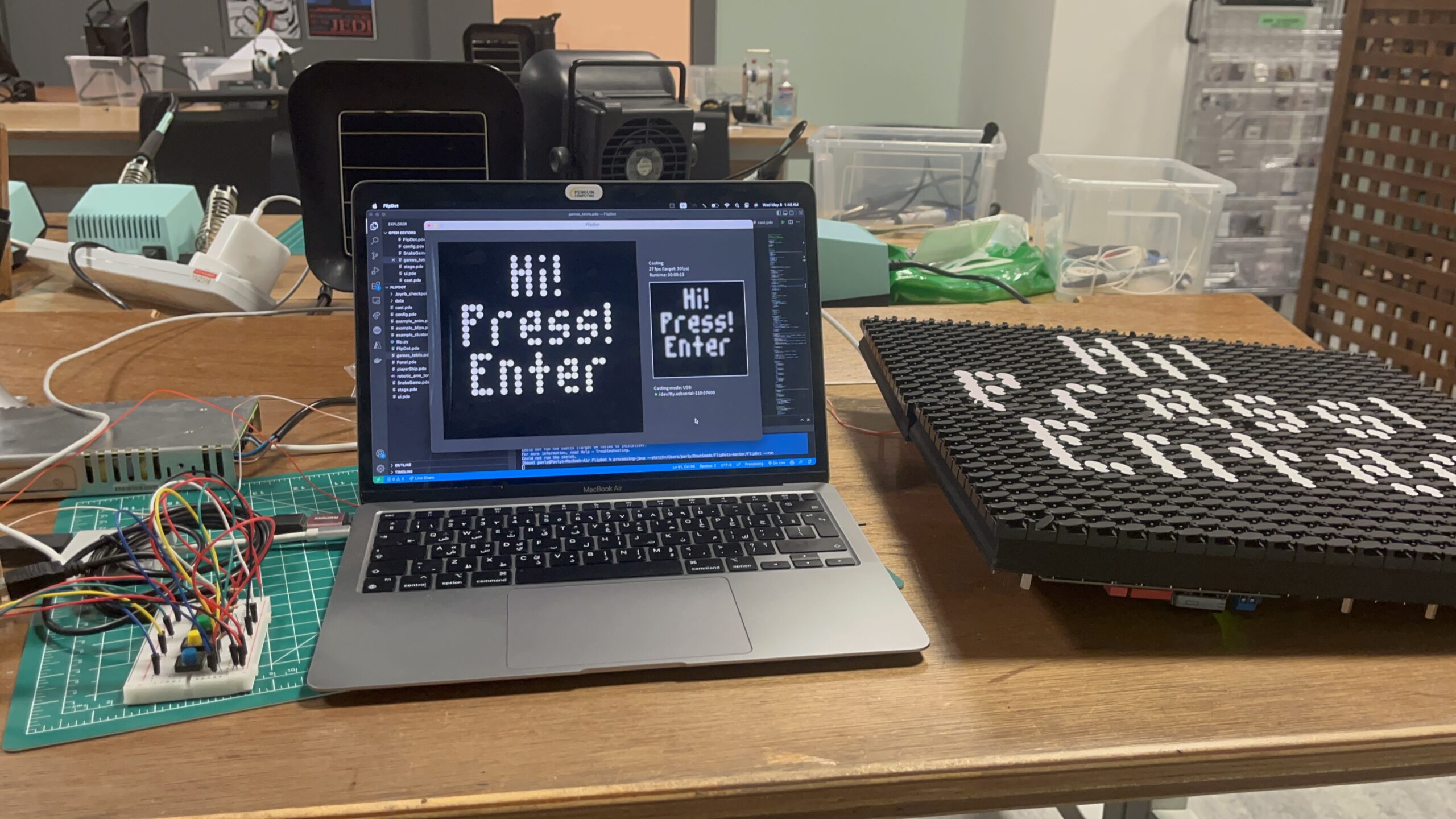
-Visual Appeal: The flip-dot display was visually engaging and drew users’ attention.
– Physical Controls: Users enjoyed the tactile experience of using physical buttons rather than a touchscreen or keyboard.
– Nostalgia Factor: For users familiar with the classic Atari games, the project evoked a sense of nostalgia and brought back positive memories.
Areas for Improvement:
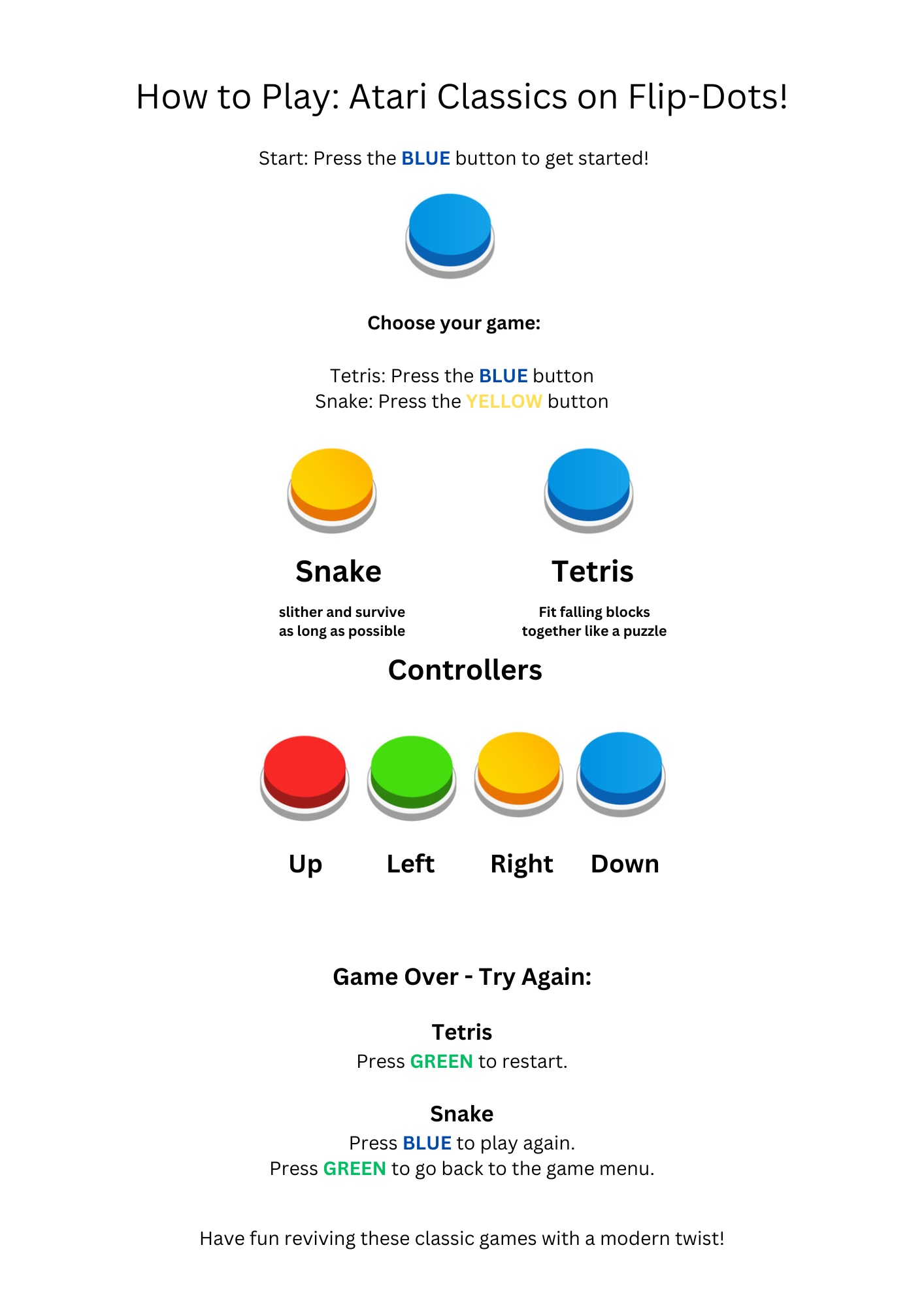
– Clear Instructions: Provide concise and easy-to-understand instructions on the display or through a separate guide.
– Intuitive Controls: Consider using more intuitive button mapping or providing visual cues on the buttons to indicate their functions. For example, arrows could represent direction in the Snake game.
Areas Requiring Explanation:
– Button Functions: The purpose and mapping of each button needed an explanation, especially for the Snake game, where the color-direction association was not intuitive.
– Menu Navigation: Entering the game menu and selecting games required clarification.
– Game Rules (for unfamiliar users): A brief overview of the basic rules and objectives of Tetris and Snake would be beneficial for users who haven’t played these games before.
Reviving Retro Gaming: Atari Classics with a Modern Twist
Concept:
This project aims to breathe new life into classic Atari games by reimagining them with interactive physical controls and a unique display using flip-dot technology. The initial implementation features two iconic games, Tetris and Snake, with the potential for future expansion.
Interaction Design:
– Buttons are connected to the Arduino and act as input devices for controlling the games.
– The Arduino communicates with the Processing program via serial communication, sending button press information.
– Processing handles game logic and generates the visuals displayed on the flip-dots.
– Another serial communication channel is established between Processing and the flip-dots to send display data.
Arduino Code:
– The Arduino code reads the button states and sends them to Processing via serial communication.
// Arduino Sketch
void setup() {
  Serial.begin(9600);         // Start serial communication at 9600 baud rate
  pinMode(3, INPUT_PULLUP);   // Set pin 3 as an input with an internal pull-up resistor
  pinMode(4, INPUT_PULLUP);   // Set pin 4 as an input with an internal pull-up resistor
  pinMode(5, INPUT_PULLUP);   // Set pin 5 as an input with an internal pull-up resistor
  pinMode(6, INPUT_PULLUP);   // Set pin 6 as an input with an internal pull-up resistor
}

void loop() {
  // Read the state of the buttons
  int buttonState3 = digitalRead(3);
  int buttonState4 = digitalRead(4);
  int buttonState5 = digitalRead(5);
  int buttonState6 = digitalRead(6);

  // Send the button states over serial, separated by commas
  Serial.print(buttonState3);
  Serial.print(",");
  Serial.print(buttonState4);
  Serial.print(",");
  Serial.print(buttonState5);
  Serial.print(",");
  Serial.println(buttonState6);  // 'println' for a new line at the end

  delay(100);  // Delay for a short period to avoid sending too much data
}
Processing Code:
The Processing code performs several key tasks:
– Game Logic: Manages game mechanics, including player movement, collision detection, and game state.
– Visuals: Generates the graphics for each game to be displayed on the flip-dots.
– Serial Communication: Receives button input data from the Arduino and sends display data to the flip-dots.
import processing.net.*;
import processing.serial.*;

void cast_setup() {
  if (!config_cast) return;
  if (castOver == 1) {
    for (int i = 0; i < netAdapters.length; i++) {
      String[] adapterAddress = split(netAdapters[i], ':');
      adaptersNet[i] = new Client(this, adapterAddress[0], int(adapterAddress[1]));
    }
  }

  else if (castOver == 2) {
    // printArray(Serial.list());
    for (int i = 0; i < serialAdapters.length; i++) {
      String[] adapterAddress = split(serialAdapters[i], ':');
      adaptersSerial[i] = new Serial(this, adapterAddress[0], int(adapterAddress[1]));
    }
  }
}

void cast_broadcast() {
  if (!config_cast) return;
  int adapterCount = netAdapters.length;
  if (castOver == 2) {
    adapterCount = serialAdapters.length;
  }

  for (int adapter = 0; adapter < adapterCount; adapter++) {
    for (int i = 0; i < panels.length; i++) {
      if (panels[i].adapter != adapter) continue;
      cast_write(adapter, 0x80);
      cast_write(adapter, (config_video_sync) ? 0x84 : 0x83);
      cast_write(adapter, panels[i].id);
      cast_write(adapter, panels[i].buffer);
      cast_write(adapter, 0x8F);
    }
  }

  if (config_video_sync) {
    for (int adapter = 0; adapter < adapterCount; adapter++) {
      cast_write(adapter, 0x80);
      cast_write(adapter, 0x82);
      cast_write(adapter, 0x8F);
    }
  }
}


void cast_write(int adapter, int data) {
  if (castOver == 1) {
    adaptersNet[adapter].write(data);
  }
  else if(castOver == 2) {
    adaptersSerial[adapter].write(data);
  }
}
void cast_write(int adapter, byte data) {
  cast_write(adapter, data);
}
void cast_write(int adapter, byte[] data) {
  if (castOver == 1) {
    adaptersNet[adapter].write(data);
  }
  else if(castOver == 2) {
    adaptersSerial[adapter].write(data);
  }
}
Challenges and Solutions:
Initially, the project aimed to use p5.js to handle the game logic and visuals. However, challenges arose in establishing reliable communication and sending data to the flip-dots. To overcome this, the decision was made to switch to Processing, which provided a more stable environment for serial communication and flip-dot control.
Proud Achievements:
Successful Integration of Hardware and Software: The project combines Arduino, buttons, and flip-dots with Processing to create a unique gaming experience.
Retro Games with a Modern Twist: Classic Atari games are revitalized with physical controls and a visually appealing flip-dot display.
Future Improvements:
Expand Game Library: Add more classic Atari games or even explore the possibility of creating new games specifically designed for this platform.
Enhance Visuals: Experiment with different animation techniques and graphical styles to further enhance the visual appeal of the games on the flip-dot display.
Refine User Interface: Explore additional input methods or create a more intuitive menu system for navigating between games.
Explore p5.js Integration: Revisit the possibility of using p5.js in the future if more robust libraries or solutions for flip-dot communication become available.
Instructions Check the full code on GitHub: https://github.com/pavlyhalim/Atari
The reading on design and disability sparked a shift in my perspective, like adjusting a lens to see the world with newfound clarity. It highlighted the often-overlooked potential of aesthetics in assistive devices, challenging the notion that functionality must come at the expense of beauty. Glasses, as a prime example, seamlessly blend utility and style, demonstrating that assistive technology can be desirable and even fashionable. This revelation resonated deeply, aligning with my belief that good design enhances not just usability but also user experience and self-perception.
It’s like realizing that accessibility isn’t just about creating universally bland solutions, but rather celebrating diversity through targeted designs that cater to individual needs and preferences. Involving artists and fashion designers in this process can inject a sense of identity and personal expression into assistive devices, transforming them from purely functional tools into extensions of oneself. The shift in language from “patients” to “wearers” and “hearing aids” to “HearWear” further emphasizes this transformation, moving away from medicalized labels towards a focus on empowerment and individuality. This reading has ignited a passion within me to advocate for inclusive design that not only accommodates but also celebrates the unique needs and aspirations of all individuals.
Ellipse in p5 move on the horizontal axis, in the middle of the screen, and nothing on Arduino is controlled by p5
Code 1
let rVal = 0;
let alpha = 255;
let left = 0; // True (1) if mouse is being clicked on left side of screen
let right = 0; // True (1) if mouse is being clicked on right side of screen

function setup() {
  createCanvas(640, 480);
  textSize(18);
}

function draw() {
  // one value from Arduino controls the background's red color
  background(255)

  // the other value controls the text's transparency value
  fill(255, 0,0)

  if (!serialActive) {
    text("Press Space Bar to select Serial Port", 20, 30);
  } else {
    text("Connected", 20, 30);
    // Print the current values
    text('rVal = ' + str(rVal), 20, 50);
    text('alpha = ' + str(alpha), 20, 70);
  }

  // click on one side of the screen, one LED will light up
  // click on the other side, the other LED will light up
  if (mouseIsPressed) {
    if (mouseX > rVal-50 && mouseX < rVal+50 && mouseY > height/2-50 && mouseY < height/2+50) {
      right = 1;
    }
  } else {
    right = 0;
  }
  ellipse(rVal, height/2, 50,50)
}

function keyPressed() {
  if (key == " ") {
    // important to have in order to start the serial connection!!
    setUpSerial();
  }
}

// This function will be called by the web-serial library
// with each new line of data. The serial library reads
// the data until the newline and then gives it to us through
// this callback function
function readSerial(data) {
  ////////////////////////////////////
  //READ FROM ARDUINO HERE
  ////////////////////////////////////

  if (data != null) {
    // make sure there is actually a message
    // split the message
    let fromArduino = split(trim(data), ",");
    // if the right length, then proceed
    if (fromArduino.length == 2) {
      // only store values here
      // do everything with those values in the main draw loop

      // We take the string we get from Arduino and explicitly
      // convert it to a number by using int()
      // e.g. "103" becomes 103
      rVal = int(fromArduino[0]);
      alpha = int(fromArduino[1]);
    }

    //////////////////////////////////
    //SEND TO ARDUINO HERE (handshake)
    //////////////////////////////////
    let sendToArduino = left + "," + right + "\n";
    writeSerial(sendToArduino);
  }
}
Exercise 2
Something that controls the LED brightness from p5
code 2
let rVal = 0;
let alpha = 255;
let left = 0; // True (1) if mouse is being clicked on left side of screen
let right = 0; // True (1) if mouse is being clicked on right side of screen

function setup() {
  createCanvas(640, 480);
  textSize(18);
}

function draw() {
  // one value from Arduino controls the background's red color
  background(map(rVal, 0, 1023, 0, 255), 255, 200);

  // the other value controls the text's transparency value
  fill(255, 0, 255, map(alpha, 0, 1023, 0, 255));

  if (!serialActive) {
    text("Press Space Bar to select Serial Port", 20, 30);
  } else {
    text("Connected", 20, 30);
    // Print the current values
    text('rVal = ' + str(rVal), 20, 50);
    text('alpha = ' + str(alpha), 20, 70);
  }


  // click on one side of the screen, one LED will light up
  // click on the other side, the other LED will light up
  if (mouseIsPressed) {
    if (mouseX <= width / 2) {
      left = 1;
    } else {
      right = 1;
    }
  } else {
    left = right = 0;
  }
}

function keyPressed() {
  if (key == " ") {
    // important to have in order to start the serial connection!!
    setUpSerial();
  }
}


function readSerial(data) {
  ////////////////////////////////////
  //READ FROM ARDUINO HERE
  ////////////////////////////////////

  if (data != null) {
    // make sure there is actually a message
    // split the message
    let fromArduino = split(trim(data), ",");
    // if the right length, then proceed
    if (fromArduino.length == 2) {
      // only store values here
      // do everything with those values in the main draw loop

      // We take the string we get from Arduino and explicitly
      // convert it to a number by using int()
      // e.g. "103" becomes 103
      rVal = int(fromArduino[0]);
      alpha = int(fromArduino[1]);
    }

    //////////////////////////////////
    //SEND TO ARDUINO HERE (handshake)
    //////////////////////////////////
    let sendToArduino = left + "," + right + "\n";
    writeSerial(sendToArduino);
  }
}
Video
Arduino code for 1 and 2
int leftLedPin = 2;
int rightLedPin = 5;

void setup() {
  // Start serial communication so we can send data
  // over the USB connection to our p5js sketch
  Serial.begin(9600);

  // We'll use the builtin LED as a status output.
  // We can't use the serial monitor since the serial connection is
  // used to communicate to p5js and only one application on the computer
  // can use a serial port at once.
  pinMode(LED_BUILTIN, OUTPUT);

  // Outputs on these pins
  pinMode(leftLedPin, OUTPUT);
  pinMode(rightLedPin, OUTPUT);

  // Blink them so we can check the wiring
  digitalWrite(leftLedPin, HIGH);
  digitalWrite(rightLedPin, HIGH);
  delay(200);
  digitalWrite(leftLedPin, LOW);
  digitalWrite(rightLedPin, LOW);


  // start the handshake
  while (Serial.available() <= 0) {
    digitalWrite(LED_BUILTIN, HIGH); // on/blink while waiting for serial data
    Serial.println("0,0"); // send a starting message
    delay(300);            // wait 1/3 second
    digitalWrite(LED_BUILTIN, LOW);
    delay(50);
  }
}

void loop() {
  // wait for data from p5 before doing something
  while (Serial.available()) {
    digitalWrite(LED_BUILTIN, HIGH); // led on while receiving data

    int left = Serial.parseInt();
    int right = Serial.parseInt();
    if (Serial.read() == '\n') {
      digitalWrite(leftLedPin, left);
      digitalWrite(rightLedPin, right);
      int sensor = analogRead(A0);
      delay(5);
      int sensor2 = analogRead(A1);
      delay(5);
      Serial.print(sensor);
      Serial.print(',');
      Serial.println(sensor2);
    }
  }
  digitalWrite(LED_BUILTIN, LOW);
}
Exercise 3
Bouncing ball
video
code 3
let velocity;
let gravity;
let position;
let acceleration;
let breeze;
let drag = 0.99;
let mass = 50;
let heightOfBall = 0;
function setup() {
  createCanvas(640, 360); // Create a canvas of 800x400 pixels

  noFill();
  position = createVector(width/2, 0);
  velocity = createVector(0,0);
  acceleration = createVector(0,0);
  gravity = createVector(0, 0.5*mass);
  breeze = createVector(0,0);
}
function draw() {
  background(215);
  fill(0);

  if (!serialActive) {
    text("Press the space bar to select the serial Port", 20, 50);
  }
  else
  {
    text("check the light.", 20, 50);

  applyForce(breeze);
  applyForce(gravity);
  velocity.add(acceleration);
  velocity.mult(drag);
  position.add(velocity);
  acceleration.mult(0);
  ellipse(position.x,position.y,mass,mass);

  if (position.y > height-mass/2) {
      velocity.y *= -0.9;  // A little dampening when hitting the bottom
      position.y = height-mass/2;

    heightOfBall = 0;

    }
    else {
      heightOfBall = 1;
    }
  }
}
function applyForce(force){
  // Newton's 2nd law: F = M * A
  // or A = F / M
  let f = p5.Vector.div(force, mass);
  acceleration.add(f);
}
function keyPressed() {
  if (key == " ") {
    // important to have in order to start the serial connection!!
    setUpSerial();
  }
}
// this callback function
function readSerial(data) {
    ////////////////////////////////////
    //READ FROM ARDUINO HERE
    ////////////////////////////////////

     if (data != null) {
    // make sure there is actually a message

    let fromArduino = split(trim(data), ",");

       // if the right length, then proceed
    if (fromArduino.length == 1) {
//sensor value is the input from potentiometer
      let sensorVal = int(fromArduino[0]);

//potentiometer value ranges from 0 - 1023
//for values less than 400,wind blows to right
      if (sensorVal < 400){
        breeze.x=1
      }
//if value between 400 and 500, wind stops so ball stops
      else if(sensorVal >= 400 && sensorVal < 500){
        breeze.x = 0
      }
//if value greater than 500, wind blows to left
      else {
        breeze.x = -1
      }
          //////////////////////////////////
          //SEND TO ARDUINO HERE (handshake)
          //////////////////////////////////
    }
//height of ball sent to arduino to check if ball on floor or not
    let sendToArduino = heightOfBall  + "\n";
    writeSerial(sendToArduino);
  }
}
code 3 Arduino
int leftLedPin = 2;

void setup() {
  // Start serial communication so we can send data
  // over the USB connection to our p5js sketch
  Serial.begin(9600);
  pinMode(LED_BUILTIN, OUTPUT);

  // Outputs on these pins
  pinMode(leftLedPin, OUTPUT);

  // Blink them so we can check the wiring
  digitalWrite(leftLedPin, HIGH);
  delay(200);
  digitalWrite(leftLedPin, LOW);


  // start the handshake
  while (Serial.available() <= 0) {
    digitalWrite(LED_BUILTIN, HIGH); // on/blink while waiting for serial data
    Serial.println("0,0"); // send a starting message
    delay(300);            // wait 1/3 second
    digitalWrite(LED_BUILTIN, LOW);
    delay(50);
  }
}

void loop() {
  while (Serial.available()) {
    digitalWrite(LED_BUILTIN, HIGH); // led on while receiving data

    int left = Serial.parseInt();
    if(left>=330){
       digitalWrite(leftLedPin, HIGH);
}

    if (Serial.read() == '\n') {
      digitalWrite(leftLedPin, left);
      int sensor = analogRead(A0);
      sensor = map(sensor,0,1023,-1,1);
      Serial.println(sensor);

    }
  }
  digitalWrite(leftLedPin, LOW);
}
This project aims to create an interactive art installation using a Flipdot display controlled by an Arduino UNO with a graphical interface powered by P5.js. The installation will allow users to create patterns or drawings on a web-based interface (using P5.js), which will then be replicated on a large Flipdot panel in real-time. This integration combines the digital and physical realms, making it a fascinating project for exhibitions, educational purposes, or interactive installations.
Reading Bret Victor’s “A Brief Rant on the Future of Interaction Design” was a wake-up call. It made me question the direction we’re heading with technology and the limitations we’re placing on ourselves by focusing solely on “Pictures Under Glass.” Victor’s point about our hands resonated deeply with me. We interact with the world through touch, manipulating objects, and receiving feedback through our fingertips. Yet, many of our current devices ignore this fundamental aspect of human capability. They offer a flat, sterile experience that limits our ability to connect with the digital world truly.
The examples he uses, like tying shoelaces or making a sandwich, were eye-opening. These everyday tasks highlight the incredible talent and nuanced control we possess. It seems almost absurd to think that the future of interaction should involve simply sliding our fingers across a screen.
Victor’s call for a more ambitious vision that embraces the full potential of our bodies and our senses is inspiring. I imagine a future where we interact with technology more naturally and intuitively, using gestures, movement, and touch to manipulate digital objects as if they were physical. This reading has challenged me to think differently about interaction design. It’s not just about creating interfaces that look sleek and futuristic; it’s about designing human-centered experiences that leverage our innate capabilities and allow us to interact with the digital world in a natural and empowering way.
I believe the future of interaction lies beyond the screen in a world where technology seamlessly integrates with our physical reality and empowers us to create, explore, and connect in ways we can only begin to imagine.
This project explores the interaction between LEDs, buttons, a potentiometer, and a buzzer to create an engaging sensory experience. Let’s break down the idea and reflect on the process.
Components and Functionality
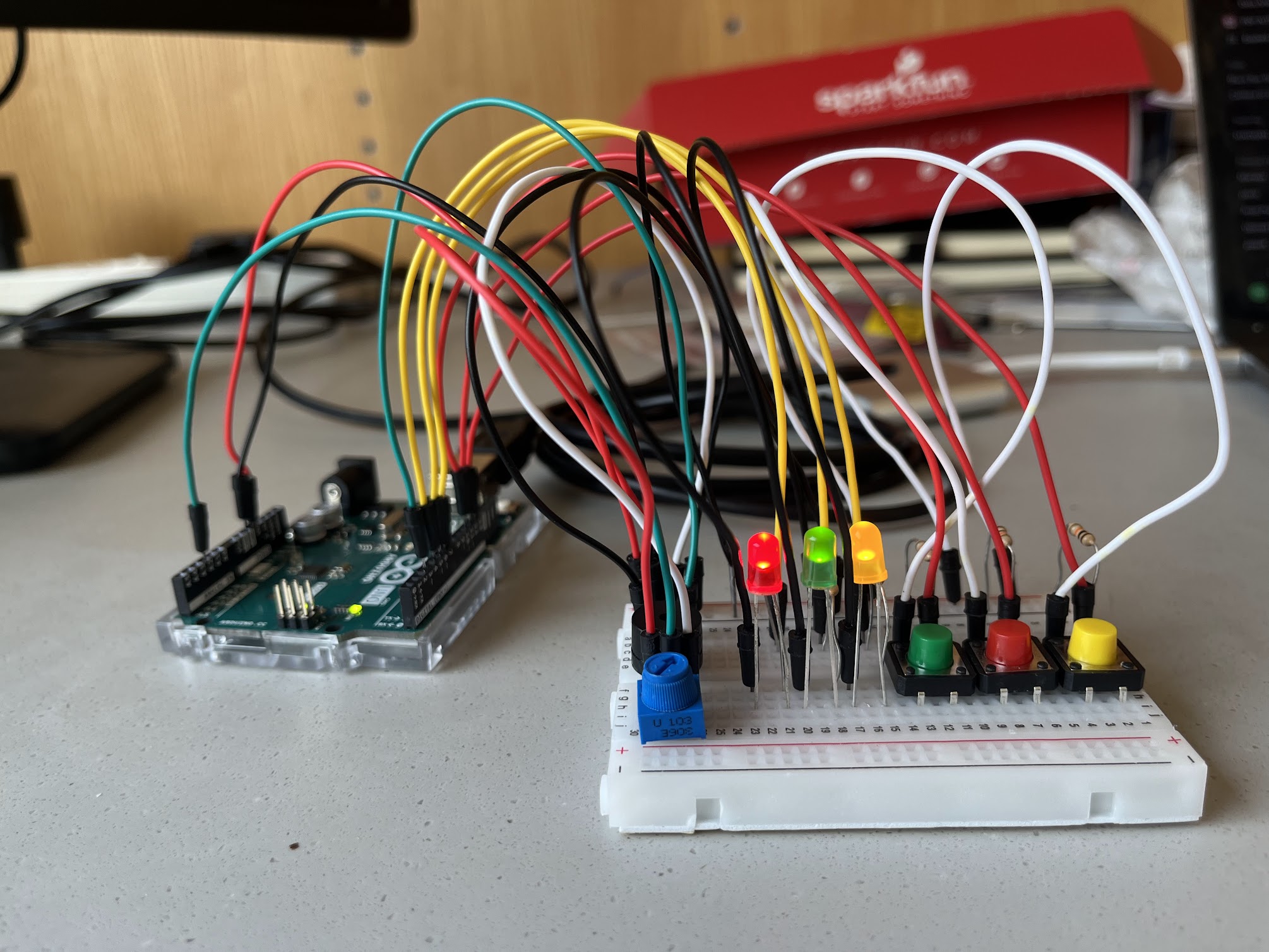
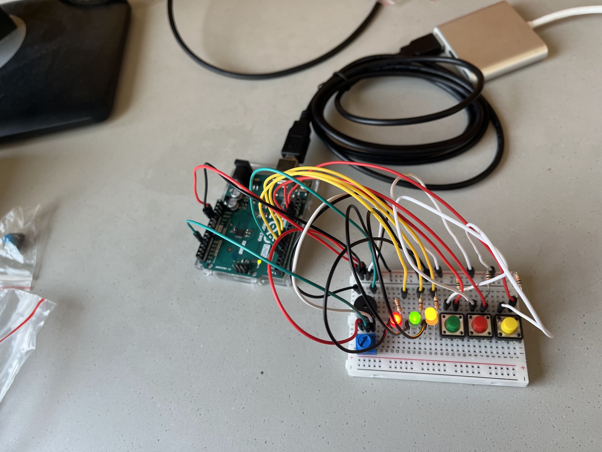
Breadboard
Arduino UNO
LEDs: These provide visual feedback based on button presses.
Buttons: Each button is associated with a specific LED. Pressing a button activates the corresponding LED and triggers a sound.
Potentiometer: controls the pitch of the sound produced by the buzzer.
Buzzer: generates sound based on the button press and the potentiometer’s readings.
330-ohm resistors (3)
10k ohm resistors (3)
Photo
Video
Schematic
Code
const int redLED = 6;
const int greenLED = 5;
const int yellowLED = 7;
const int redButton = 12;
const int greenButton = 11;
const int yellowButton = 13;
const int potPin = A2;
const int buzzerPin = 3;

void setup() {
  pinMode(redLED, OUTPUT);
  pinMode(greenLED, OUTPUT);
  pinMode(yellowLED, OUTPUT);

  pinMode(redButton, INPUT_PULLUP);
  pinMode(greenButton, INPUT_PULLUP);
  pinMode(yellowButton, INPUT_PULLUP);

  // Initialize Serial for debugging
  Serial.begin(9600);
}

void loop() {
  // Read potentiometer value
  int potValue = analogRead(potPin);
  // Map potentiometer value to a frequency range (e.g., 100 Hz to 2000 Hz)
  int frequency = map(potValue, 0, 1023, 100, 2000);

  // Check each button and activate the corresponding LED and buzzer
  if (digitalRead(redButton) == LOW) {
    digitalWrite(redLED, HIGH);
    tone(buzzerPin, frequency);  // Play buzzer at mapped frequency
    delay(100);  // delay
  } else {
    digitalWrite(redLED, LOW);
  }

  if (digitalRead(greenButton) == LOW) {
    digitalWrite(greenLED, HIGH);
    tone(buzzerPin, frequency + 100);  // Slightly higher pitch for green button
    delay(100);  // Debounce delay
  } else {
    digitalWrite(greenLED, LOW);
  }

  if (digitalRead(yellowButton) == LOW) {
    digitalWrite(yellowLED, HIGH);
    tone(buzzerPin, frequency + 200);  // Even higher pitch for yellow button
    delay(100);  // Debounce delay
  } else {
    digitalWrite(yellowLED, LOW);
  }
  delay(10);
}
Reflections
Seeing the LEDs light up and hearing the buzzer’s pitch change in response to my actions was incredibly satisfying. It’s amazing how these simple components, combined with code, can create such an engaging experience.
I particularly enjoyed the challenge of mapping the potentiometer’s value to the buzzer’s frequency. Finding the proper range to create pleasing sounds and ensuring smooth transitions between pitches was a fun puzzle.
Challenges
– Debouncing: Ensuring buttons register single presses can be tricky. The current code uses simple delays, but more robust debouncing techniques could be implemented.
– Sound Complexity: The buzzer produces simple tones. Exploring libraries like Mozzi could enable more complex and engaging soundscapes.
Potential Enhancements
Light patterns: Explore blinking or fading LEDs for more dynamic visuals.
Multiple tones/melodies: Utilize libraries to create richer audio experiences.
Interactive games: Design games based on button presses and timing.
LCD display: Incorporate a display to show instructions or scores.
Concept
I built a cool project using an ultrasonic sensor and an Arduino! It measures the distance to objects and tells me how far away they are using LEDs. If something is close, a red light blinks faster the closer it gets – like a warning. A green light turns on if it’s further away, so I know it’s safe. I can even start and stop the sensor with a button, which is pretty neat.
Video
Components Required:
Arduino Uno (or any compatible board)
Ultrasonic Sensor (HC-SR04 or similar)
Red LED
Green LED
220-ohm resistors (2 pieces) & 10k-ohm resistor
Push button
Jumper wires
Breadboard
Schematic
Code
const int trigPin = 3;    //Trig
const int echoPin = 2;    //Echo
const int redLedPin = 13;  //RedLED
const int greenLedPin = 12; //GreenLED
const int buttonPin = 4;  //PushButton

int blinkInterval = 500; //BlinkInterval
bool projectRunning = false; //FlagToStart

void setup() {
  Serial.begin(9600);
  pinMode(trigPin, OUTPUT);  //SetUltrasonicSensor
  pinMode(echoPin, INPUT);
  pinMode(redLedPin, OUTPUT);
  pinMode(greenLedPin, OUTPUT);
  pinMode(buttonPin, INPUT_PULLUP); //SetButton
}

void loop() {
  if (digitalRead(buttonPin) == LOW) {
    projectRunning = !projectRunning; //Toggle project state
  }

  if (projectRunning) {
    //Measure distance with ultrasonic sensor
    long duration = 0;
    long distance = 0;
    int retryCount = 0;
    const int maxRetries = 5; //Set a max number of retries
    while (duration == 0 && retryCount < maxRetries) {
      digitalWrite(trigPin, LOW);
      delayMicroseconds(2);
      digitalWrite(trigPin, HIGH);
      delayMicroseconds(10);
      digitalWrite(trigPin, LOW);
      duration = pulseIn(echoPin, HIGH);
      retryCount++;
    }

    if (duration != 0) {
      distance = duration * 0.034 / 2; //Convert to cm
    }

    //Print distance to Serial Monitor
    Serial.print("Distance: ");
    Serial.print(distance);
    Serial.println(" cm");

    //Control LED based on distance
    if (distance <= 50) {
      digitalWrite(greenLedPin, LOW);
      blinkInterval = map(distance, 0, 50, 100, 1000);
      digitalWrite(redLedPin, HIGH);
      delay(blinkInterval);
      digitalWrite(redLedPin, LOW);
      delay(blinkInterval);
    } else {
      digitalWrite(redLedPin, LOW);
      digitalWrite(greenLedPin, HIGH);
    }
  } else {
    //Turn off both LEDs when the project is not running
    digitalWrite(redLedPin, LOW);
    digitalWrite(greenLedPin, LOW);
  }
}
Building this project was a real learning curve! Seeing the LEDs react to the distance measurements was super cool, but getting there wasn’t always smooth sailing. The sensor readings were a bit wonky at first, picking up on random noise and stuff. I had to get creative with the code to filter that out and make sure it was actually measuring the right things.
I’ve always been fascinated by the intersection of technology and art, so reading about these interactive projects really resonated with me. It’s incredible how specific themes, like theremins and video mirrors, keep popping up, proving that some ways of interacting are just inherently enjoyable. However, I realize that the true magic lies not in the technology itself but in the experience it creates.
Initially, I was drawn to the technical aspects of these projects: the sensors, the code, and the gadgets. But now I see them as tools, like a painter’s brush or a musician’s instrument. Technology is simply a means to an end, and the real focus should be on the interaction and the meaning it conveys.
One of my most important takeaways is the idea of “shutting up and listening.” As creators, it’s easy to fall into the trap of over-explaining our work, dictating how it should be interpreted. But that approach stifles the audience’s ability to explore and discover their own meaning. Instead, we should create experiences that invite participation, spark curiosity, and allow for diverse interpretations.
These readings have ignited my passion to explore interactive art more deeply. I want to create projects beyond mere novelty and offer meaningful experiences that evoke emotions and stimulate thought. I’m excited to experiment with different technologies and approaches, always considering the importance of observation and listening to understand how people interact with and interpret my work.
I believe that interactive art has the potential to bridge the gap between the creator and the audience, fostering a sense of connection and shared experience. By focusing on meaningful interaction and embracing the audience’s role in shaping the experience, we can create art that is not only engaging but also transformative.