Explore Nature’s Elements – Final Project by Hana

For the final project, I decided to create an experience which involves interactivity through buttons, led lights, a fan and a screen. During finals week we have so much to work on that we neglect nature and its healing powers, so I decided to bring that indoors and onto our screens as a way to create an enjoyable and relaxing experience.

This project consists of the screen display part which is coded on P5, and the user interactivity with buttons, a potentiometer, a fan and the neopixel ring lights. Here is a demo to show the experience better:

Interaction

One can switch through the different elements to experience them: rain, fire, or earth&wind. For a more immersive feel beyond the simulations on the screen, I decided to have light shows on a neopixel ring with patterns which imitate what is happening on the screen. The magnitude of the potentiometer affects what is happening in the simulations.

Higher magnitude in rain leads to more raindrops and at higher speeds. In the lightshow this translates to the raindrops rotating faster. The fan is activated during rain, as wind is often associated with rain.

Higher magnitude in fire leads to more fire particles and a bigger spread (essentially more fire). In the lightshow this is shown by how high the fire reaches the top of the ring. The fan is off at this time.

Magnitude in earth&wind affects the direction of the wind on the screen. The light show is unrelated to the work of the potentiometer, as the light show is imitating the piling of the leaves on the screen, which happens at a constant rate regardless of the values of the potentiometer. It is interesting to note that the constant rate of the leaf piling creates an hourglass effect on both the screen and the neopixel ring (the pile gets higher after a constant x amount of time). The fan is turned on to imitate the wind.

Arduino

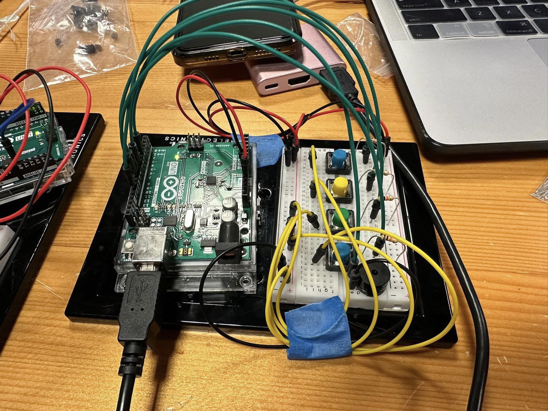
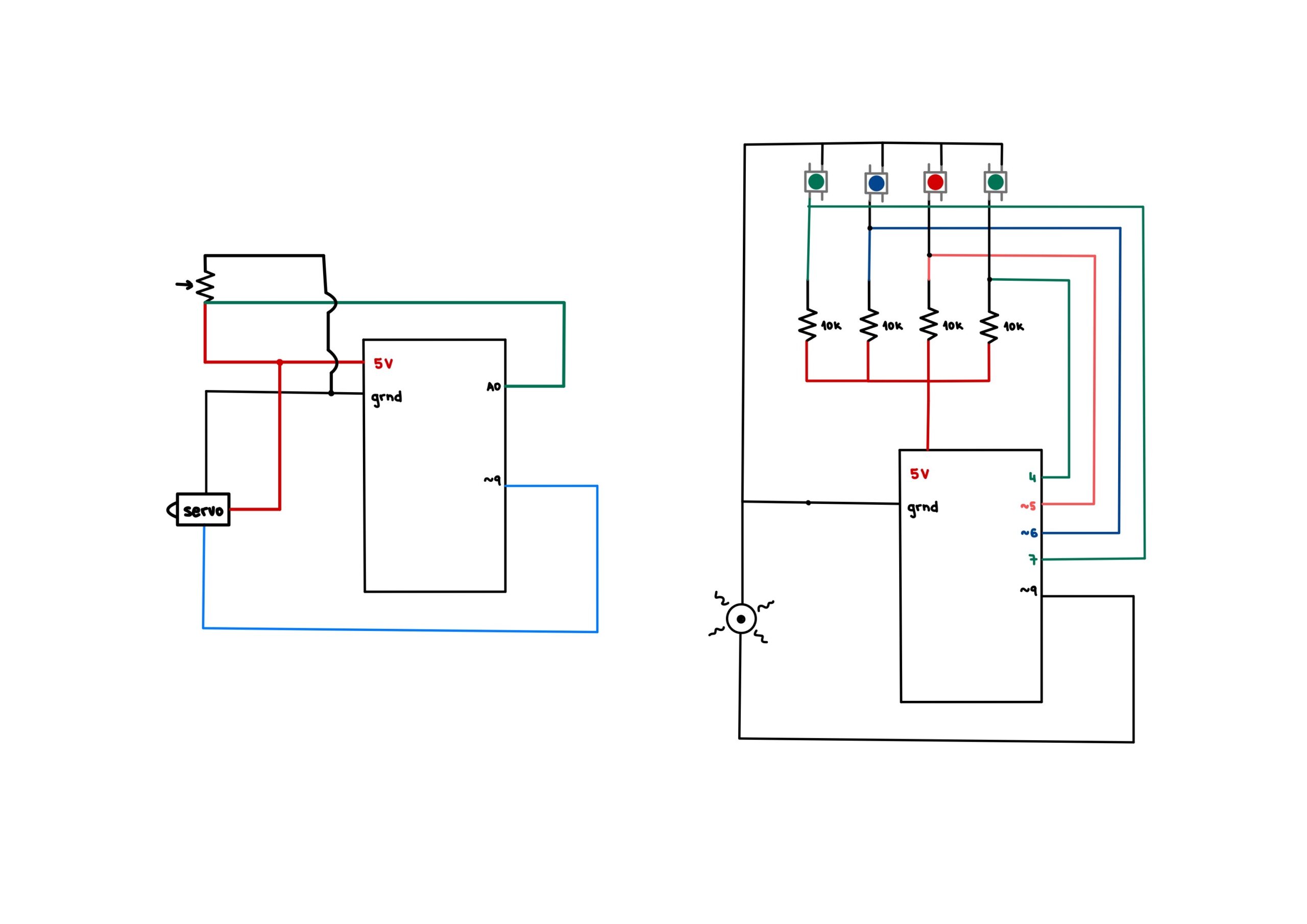
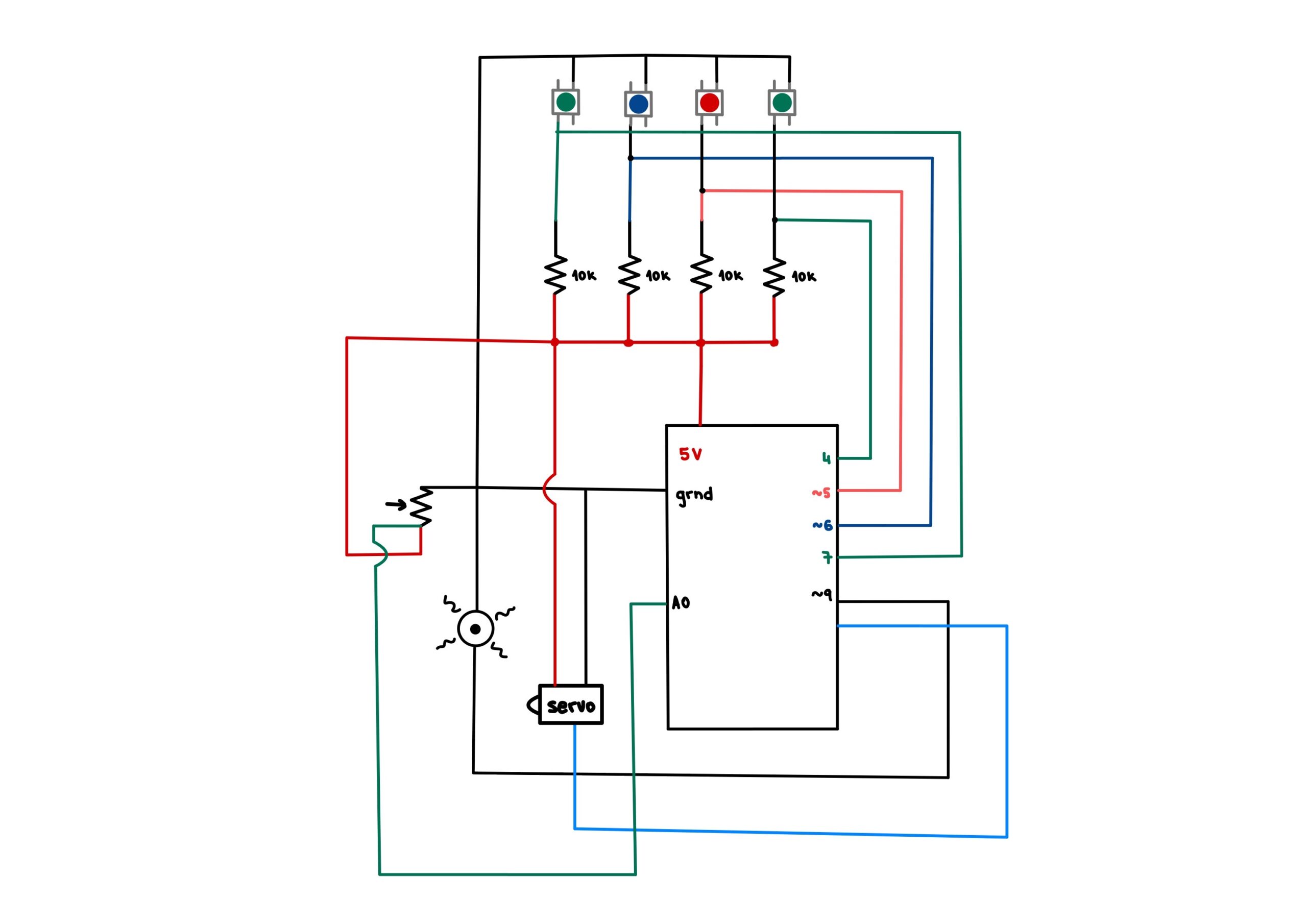
The arduino works by taking as input the values of the switches and the potentiometers, and outputting the neopixel light show patterns as well as turning the fan on and off when appropriate.

The Fan

The fan required a higher voltage than the 5V that arduino supplies, so in order to get it to work I had to use a different power source and use a transistor in order to control the fan through the arduino. As for code, I simply had to do a digitalWrite of HIGH on the appropriate pin when I wanted it on and digitalWrite of LOW when I wanted it off.

Light Shows

I had to come up with my own patterns for the light shows to imitate best what I had come up with for the screen. Because of the ring shape of the neopixel, I had to get very creative, since the screen is a rectangle.

For the raindrops, I decided to create 4 raindrops which go around in a clockwise direction, and the magnitude of the rain would affect the speed at which they go around. To create a more interesting effect, I created the raindrops as a sort of trail, where the pixel at the front was the brightest, and the 2 pixels behind it each get dimmer, followed by fully dim pixels to distinguish between the rain drops. Here is the code for this pattern:

void raindrops(int del) {
  //map potentiometer value to del
  del = map(del, 40, 1020, 150, 30);
  // a total of 24 pixels
  // separate into 4 sections by tackling 6 pixels at a time
  for(int i=0; i<6; i++) { 
    //first pixels in the section are dark
    pixels.setPixelColor(i, pixels.Color(0, 0, 0));
    pixels.setPixelColor(i+6, pixels.Color(0, 0, 0));
    pixels.setPixelColor(i+12, pixels.Color(0, 0, 0));
    pixels.setPixelColor(i+18, pixels.Color(0, 0, 0));

    //second pixels in the section are dark
    pixels.setPixelColor(i+1, pixels.Color(0, 0, 0));
    pixels.setPixelColor(i+7, pixels.Color(0, 0, 0));
    pixels.setPixelColor(i+13, pixels.Color(0, 0, 0));
    pixels.setPixelColor(i+19, pixels.Color(0, 0, 0));

    //third pixels in the section are dark  
    pixels.setPixelColor(i+2, pixels.Color(0, 0, 0));
    pixels.setPixelColor(i+8, pixels.Color(0, 0, 0));
    pixels.setPixelColor(i+14, pixels.Color(0, 0, 0));
    pixels.setPixelColor(i+20, pixels.Color(0, 0, 0));

    //fourth pixels in the section are dim
    pixels.setPixelColor(i+3, pixels.Color(20, 20, 20));
    pixels.setPixelColor(i+9, pixels.Color(20, 20, 20));
    pixels.setPixelColor(i+15, pixels.Color(20, 20, 20));
    pixels.setPixelColor(i+21, pixels.Color(20, 20, 20));

    //fifth pixels in the section are brighter
    pixels.setPixelColor((i+4)%NUMPIXELS, pixels.Color(100,100,100));
    pixels.setPixelColor((i+10)%NUMPIXELS, pixels.Color(100,100,100));
    pixels.setPixelColor((i+16)%NUMPIXELS, pixels.Color(100,100,100));
    pixels.setPixelColor((i+22)%NUMPIXELS, pixels.Color(100,100,100));

    //sixth pixels (at the front) in the section are the brightest
    pixels.setPixelColor((i+5)%NUMPIXELS, pixels.Color(200, 200, 200));
    pixels.setPixelColor((i+11)%NUMPIXELS, pixels.Color(200, 200, 200));
    pixels.setPixelColor((i+17)%NUMPIXELS, pixels.Color(200, 200, 200));
    pixels.setPixelColor((i+23)%NUMPIXELS, pixels.Color(200, 200, 200));

    pixels.show();   // Send the updated pixel colors to the hardware.

    delay(del); //delay affects how fast the raindrops are moving
  }
}

For the fire, I decided to have the fire start at the bottom of the ring, and get reach higher the higher the value of the potentiometer. To create a realistic fire crackling effect, I had to experiment a lot with colors and dimness, the colors at the bottom had to be more yellow and brighter, and the colors at the top had to be more red and dimmer – and this all had to be relative to the total height of the fire. To achieve this, I had to do a lot of calculations and a lot of experimenting until I got it right. Here is the code which gave me the desired effect:

void fire(int maxNum){ //maxNum should be 4 to 12
  //maxNum refers to the height of the fire. the number corresponds 
  //to how many pixels will be colored on each side.
  maxNum = map(maxNum, 40, 1024, 4, 12);

  //changing delay so that the fire crackles and changes more
  //the larger the fire is
  DELAYVAL = map(maxNum, 4, 12, 50, 25);

  for(int i=0; i<maxNum; i++) { 
    //calculating the dimness in relation to how many pixels there are
    //in total
    double percentage=1-0.1*map(i, 0, maxNum, 0, 10);

    //do not dim the first maxNum/3 pixels
    //the fire at the bottom must be brightest
    if(i>maxNum/3){
      // pixels.setPixelColor(i, pixels.Color(int(random(100,255)*0.1*(maxNum-i)), int(random(40)*0.1*(maxNum-i)), 0));
      // pixels.setPixelColor(NUMPIXELS-i, pixels.Color(int(random(100,255)*0.1*(maxNum-i)), int(random(40)*0.1*(maxNum-i)), 0));
      pixels.setPixelColor(i, pixels.Color(int(random(100,255)*percentage), int(random(40)*percentage), 0));
      pixels.setPixelColor(NUMPIXELS-i, pixels.Color(int(random(100,255)*percentage), int(random(40)*percentage), 0));
    }
    else{
      //full brightness
      pixels.setPixelColor(i, pixels.Color(random(150,255), random(10,60), 0));
      pixels.setPixelColor(NUMPIXELS-i, pixels.Color(random(150,255), random(10,60), 0));
    }

    pixels.show();   // Send the updated pixel colors to the hardware.

    delay(DELAYVAL); // Pause before next pass through loop

  }
  //turn off the pixels above the current height, if the height decreases
  for(int i=maxNum; i<13; i++) {
    pixels.setPixelColor(i, pixels.Color(0,0,0));
    pixels.setPixelColor(NUMPIXELS-i, pixels.Color(0,0,0));
  }
}

For the leaves, I wanted to imitate the pile of leaves which is being accumulated on the screen. So I get the level of pile that has been reached from P5, and light up a corresponding number of pixels. I use alternating shades of pink to imitate the colors of the leaves on the screen, which are also alternating. Here is the code:

void leaves(int leavesNum) {
  for(int i=0; i<leavesNum; i++) {
    //turn on fan
    digitalWrite(fan, HIGH);

    //light up two pixels at a time on each side
    //left side
    pixels.setPixelColor(2*i, pixels.Color(255, 0, 144));
    pixels.setPixelColor(2*i+1, pixels.Color(255, 69, 174));

    //right side
    pixels.setPixelColor(NUMPIXELS-2*i, pixels.Color(255, 0, 144));
    pixels.setPixelColor(NUMPIXELS-2*i+1, pixels.Color(255, 69, 174));

    pixels.show();
    delay(1);
  }
}

Beyond that in arduino, I receive values from the buttons to determine which simulation to experience, and display the appropriate light show, and turn on and off the fan whenever needed. I will discuss the arduino/P5 connection below.

P5

For the simulations, I utilized objects and arrays to create them. If you notice, each of the simulations is made up of small similar particles which are created and disappear in different ways. We have raindrops, fire particles and leaves. The code for each of the classes is quite similar, with small differences to create the different simulations, as the particles look and behave differently for each of the simulations, but they follow a similar structure. Here is the code for one of them:

class RainDrop {
  constructor() {
    //randomly decide horizontal location
    this.x = random(0, width);
    //start at the top of the screen
    this.y = 0;
    //random vertical speed
    this.vy = random(5,8);
    //random vertical diameter
    this.d = random(5,8);
    //color variation, create different shades
    //of light blue
    this.R = random(190,200);
    this.G = random(190, 200);
    this.B = random(200,255);
  }

  //finished when they reach the bottom of the screen
  finished() {
    return this.y > 600;
  }

  //update postition based on vertical speed
  update() {
    //add additional boost based on the value of the 
    //potentiometer to increase vertical speed
    this.y += this.vy + map(potVal, 100, 1020, 0, 3);
  }

  //drawing out the particle
  show() {
    noStroke();
    fill(this.R, this.G, this.B);
    ellipse(this.x, this.y, 5, this.d);
  }
}

And here is how the objects are created, updated and deleted:

function create_rain() {
  //redraw rain background
  image(rain_bg, 0, 0, 600, 400);
  
  //max num of raindrops created at a time
  //determined by the potentiometer
  let maxI = map(potVal, 40, 1020, 2, 10);
  
  if(frameCount%5==0){
    for (let i = 0; i < maxI; i++) { 
      let p = new RainDrop();
      rain_drops.push(p);
    }
  }
  //update raindrops, and delete them when they are finished
  for (let i = rain_drops.length - 1; i >= 0; i--) {
    rain_drops[i].update();
    rain_drops[i].show();
    if (rain_drops[i].finished()) {
      rain_drops.splice(i, 1);
    }
  }
}

Since the code for the other simulations follows a similar structure, I will not attach it so as not to be repetitive.

P5/Arduino Communication

At first a handshake is established to ensure communication exists before proceeding with the program:

//arduino code

while (Serial.available() <= 0) {
    Serial.println("-1"); // send a starting message
    delay(300);            // wait 1/3 second
  }

Then, the arduino constantly sends the values of the potentiometer and the values of which button was pressed last. It reads from P5 the value of the leaf pile, which it uses later for the light show:

int leavesNum = Serial.parseInt();
if (Serial.read() == '\n') {
   Serial.print(potPosition);
   Serial.print(",");
   Serial.println(currentButton);
}

Here is how P5 reads these values and also sends the leaf pile value:

// This function will be called by the web-serial library
// with each new *line* of data. The serial library reads
// the data until the newline and then gives it to us through
// this callback function
function readSerial(data) {
  ////////////////////////////////////
  //READ FROM ARDUINO HERE
  ////////////////////////////////////

  if (data != null) {
    // make sure there is actually a message
    // split the message
    let fromArduino = split(trim(data), ",");
    // if the right length, then proceed
    if (fromArduino.length == 2) {
      // store values 
      //potentiometer value
      potVal = fromArduino[0];
      currentButton = fromArduino[1];
    }

    //////////////////////////////////
    //SEND TO ARDUINO HERE
    //////////////////////////////////
    let sendToArduino = leaf_bg_choice+1 + "\n";
    writeSerial(sendToArduino);
  }
}

Strengths

As a computer science student, I am comfortable with programming. For this project I wanted to challenge myself creatively. From the creativity of the idea itself, to the screen simulations, light shows and even the crafty parts of assembling the interactive box – I pushed myself creatively as much as I could. This was an incredible learning experience for me. I learned that I can be quite resourceful even with hand work such as creating the box out of cardboard and paper, creating a cardboard ring and pinning down cloth to create a ‘lampshade’ for the neopixel. I also had so many connections and circuits, and that lead to many challenges, but it also taught me so much.

As for the user experience, I think it serves its purpose quite well – it is very simple in its usage, that the testers which you will see below required no instruction before or after to learn how to use it. And it is quite a relaxing experience, you just get to play around and enjoy the different elements, and enjoy my creative efforts at visual arts – whether it is the screen simulations or the light shows. The testers particularly enjoyed the light shows, and were very pleasantly surprised by the fan.

Weaknesses

While working on this project I ran into problem after problem. Starting with the problems I anticipated well in advance, such as learning how to use a neopixel, learning how to connect a fan and learning how to solder. These took only a matter of seeking out help from my professor and/or the internet depending on the task – so they were easier challenges to overcome, I just needed to educate myself on how to do them.

The unexpected problems were quite tough. Since I am dealing with arrays of objects in my code, I had to work on optimizing the code so I do not overwork the computer and have it result to low fps. I already had plenty of experience with that in my midterm project, so this was a relatively easy fix too.

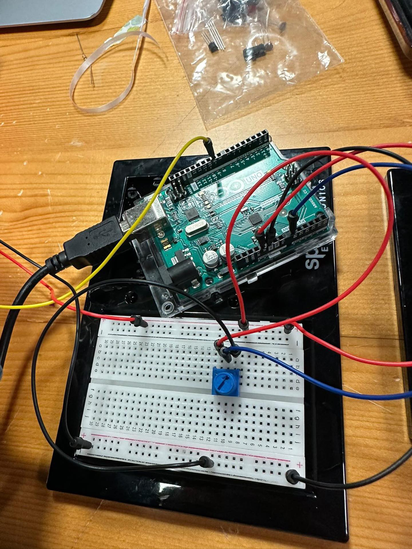
My biggest problem was with the potentiometer. Unfortunately, I am still unsure that I solved the issue at the root – but I learned how to avoid the problem. As long as I arrange my circuits evenly, and keep the wires neat and straight, the potentiometer will give me values that are stable enough for my purposes. But the problem is that the values are not entirely stable. For my purposes though, the problem is somewhat solved – at least enough for my project to work fine.

I believe a lot of the problem from above came from using a breadboard, if I used soldering instead I would have a more stable connection and thus more stable values. In a case where this was a more permanent installation, I would most definitely have to switch out of the breadboard – but this works currently.

User testing

I had two people come and test the project with no instructions beforehand. Both of them had no problems figuring out exactly how the experience works and being able to play around with it exactly as intended. They understood exactly what the buttons and the potentiometer did and would check the screen and the neopixel for the results of their work with the potentiometer.

The simplicity of the interactions worked very well, and both testers reported to have had an enjoyable and relaxing experience.

One area of improvement is with the buttons. The buttons themselves are not very sensitive, and the cardboard box is soft, so the user has to push hard to change the simulation. I put support right underneath the buttons to combat this, but it still wasn’t enough to entirely eliminate the inconvenience. However, the user does not need to push too hard, so it is easy to get used to pushing it the right amount – for my own tests I experienced no problems, but people using it for the first time faced a few challenges.

To fix the responsiveness of the buttons, I would switch out the cardboard box for something stiffer and stronger, like acrylic or wood.

Link to code

Final Project – Feel Nature Elements

Concept

The concept behind my project is to create an experience rather than a game or a tool. Similarly to my midterm project, I want to use nature elements to create a slow, relaxing and enjoyable experience for the user. The experience will receive user input through the use of switches and potentiometers, and the output will be both on the screen (P5) and off it (Arduino, neopixels and a fan). The idea is that the user can choose to switch between 4 different elements to experience – water, fire, sun and flora. There will be 4 color coordinated switches which will display a different element on the screen for the user. Once the user chooses the element, they will be shown the simulation on screen (rain for water, fire, sun, and a tree with leaves falling for flora), and the corresponding colors will flash on the neopixels to create a more immersive feel. There will be a potentiometer for the user to change different magnitudes – amount of rain, the size of the fire, the number of rays/brightness of the sun, the amount of wind blowing the leaves. The changes will reflect on the colors and blinking/simulations on the neopixels. They will also affect the fan, with the wind and the rain controlling the speed of the fan.

Arduino

The arduino will have 4 buttons to choose between the elements. It will have a potentiometer to control magnitudes. It will also have neopixels and a fan which will help simulate the elements better for a more immersive feel.

It will send to P5 the values from the switches and the potentiometer.

It will use both of the above mentioned values to simulate the lights on the neopixels and the speed of the fan. There will be different light simulations for each element at different magnitudes.

P5

I will utilize arrays of objects to create things such as raindrops, fire particles, leaves and sun rays, in order to create the simulations.

The values of which element is currently on and at what magnitude will be pulled from the Arduino.


Final Project Preliminary Concept – Experience Nature Through Arduino & P5JS

Concept

The inspiration for this idea came from the different colored LEDs included in our kits. I saw each representing a different element/object in nature (blue-water, red-fire, yellow-sun, green-earth/plants), and I delved deeper into that to develop my idea. I would like to create a system in which the user can interact with the Arduino and see on the screen and on the Arduino their interaction with ‘nature’. Similarly to my midterm project, “Zen Garden”, I find nature to be very relaxing and an important component of life – and technology somewhat draws us away from nature by taking up a lot of what could potentially be ‘outdoors time’. This is my way of once again bringing nature to the technology.

Implementation

For the implementation, I intend to have a switch to switch between the different elements – or 4 switches so the used chooses which element they would like. P5js will show simulations of rain for water, fire, leaves falling off a tree for plants, and the sun and its rays for the sun. To create a slightly more immersive feel, I will use the RGB LED which will light up in the appropriate color, and animate dimness and brightness according to what is on the screen. Furthermore, there will be a potentiometer with which the user can control a different magnitude for each element. For water – the amount of raindrops, for fire – how large the fire is, for plants – the wind direction in which leaves fall, and for the sun – the number of sun rays shown.

Week 10 – Musical Instrument

by Ajla and Hana

Concept

This week’s assignment was to create a simple musical instrument using the Arduino. Hana and Ajla decided to create a simplified piano and drum. In order to do so, we utilized switches and a servo motor. We controlled the speed of the servo motor using a potentiometer. The notes are played by pressing the buttons. The buttons stop producing noise when released.

Servo circuit


Implementation

To implement our musical instrument, we used a potentiometer, switches, a piezoelectric buzzer, resistors, wires and an Arduino. By connecting the switches in parallel we were able to preserve voltage across all components. Even though it was possible to connect everything on one breadboard, we decided to separate it in order to make the instrument user friendly. Furthermore, since many digital inputs were used, the separation ensured that there would not be any overcrowding while presenting the final product.The sketches below show both the two Arduino setup we used and one Arduino setup.

The code was written for both Arduino. Hana wrote the code for the switches and Ajla wrote the code for the drum. The drum was made using a metal screw, silk ribbon and tape which was attached to the servo hand. By pressing the four switches, notes, stored in an array, were played. The drum hit a piece of cardboard in order to produce noise.

Two Arduino
One Arduino

Here is the code for playing the notes:

// if button1 is pressed, plays first note
  if(button1State==1) {
    tone(9, notes[0]);
  }

// if button2 is pressed, plays second note

  if(button2State==1) {
    tone(9, notes[1]);
  }

// if button3 is pressed, plays third note

  if(button3State==1) {
    tone(9, notes[2]);
  }

// if button4 is pressed, plays fourth note

  if(button4State==1) {
    tone(9, notes[3]);
  }

// if buttons are release, no note is played

  if(button1State==0 && button2State==0  && button3State==0 && button4State==0) {
    noTone(9);
  }
  
  
  delay(1);  // delay in between reads for stability

Here is the code that ran the servo in a 90 degree range:

void loop() {
  int p_value  = analogRead(p_meter);

  int value = map(p_value, 0, 1024, 10, 20);
  for (int i=45; i<90; i += value) {
    pos1 = 0 + (i*2);          // servo1 from 0 to 90 degrees
    myservo1.write(pos1);      // move the servo
    delay(50);  
  }
 
  for (int i=45; i<90; i += value) {
    pos1 = 90 - i*2;           // servo1 from 90 to 0 degrees
    myservo1.write(pos1);      // move the servo
    delay(50);
  }
}

Challenges

The assignment came with a few challenges. Firstly, since the piezoelectric buzzer cannot take multiple inputs at once, it was important to play each note once, without pressing others since that would destroy the quality of the sound. Secondly, the notes play continuously if the button is pressed, even once. That is why we added the last if statement that checks whether all buttons are not pressed, in which case it plays no sound. Thirdly, the servo is quite tricky to use at high speeds. It gets more imprecise as the speed goes up. So, controlling it with the potentiometer was quite hard to do precisely. Lastly, since the angle of motion changes as the speed increases, it was hard to mount the servo on anything as it would immediately fall down once the speed was changed. This became quite frustrating that we decided to just hold the servo in the end to showcase the tempo of the “drum”. All in all, this assignment came with quite a few challenges. Some of them we tried to attempt and won, such as the notes, but some of them remain to be defeated due to the lack of time and materials we had at the time of making this project.

Reflection

Our team went back and forth on ideas on what to do as an instrument because neither of us are musically inclined. However, we landed on this idea after a few iterations. We struggled quite a bit to get everything right, as was mentioned in the challenges above, but we overcame them with solutions such as only playing one note at a time, and having to hold the servo since it would not stay mounted. Overall, it was a great learning experience, but I realized that for the final project I will most probably not delve into anything sound or music related since my creativity is a lot more limited.

Week 9 – Light Switch and Dimmer

For this weeks homework I decided to continue my work from class and make use of the switch for the digital sensor and the light sensor for the analog one.

I decided to do quite a simple light attached to the switch, when the switch is on the light is on, when you are no longer pressing the switch, the light goes off.

Here is the simple code:

// read the input on digital pin 2:
int buttonState = digitalRead(pushButton);

// if switch is on, turn LED on
if(buttonState==1) {
  digitalWrite(8, HIGH);
}
// if switch is off, turn LED off
else {
  digitalWrite(8, LOW);
}

For the analog sensor, I wanted to do a light dimmer where the dimness corresponds to the dimness that the sensor catches. This required a bit of math and a few if statements, because it is hard to achieve very low values with a light sensor, and unless the values are very low, the LED is quite bright.

Here is the code for that below:

// read the input on analog pin A2:
float sensorValue = analogRead(A2);

// exponential value for analogLEDValue
int analogLEDValue = 25.5*pow(10,(sensorValue/950));

// some more tweaking to get a more drastic change in output
if(analogLEDValue<200) {
  analogLEDValue=analogLEDValue/2-50;
}
else if(analogLEDValue<150) {
  analogLEDValue=analogLEDValue/4-50;
}
// control so it does not go <0
if(analogLEDValue<0){
  analogLEDValue=0;
}

// output
analogWrite(6, analogLEDValue);

Here is the demo:

Unusual Switch

Concept

I was looking around in my room to find something that uses simple motion to work, and I thought of my drawers. This is how I came up with my drawer switch. I set up the circuit, and taped two large foil pieces to the coils and onto the inside of the drawer as shown in the photo below:

Challenges:

Due to illness I had to miss the previous class, so I relied on Youtube and online tutorials to learn how to create circuits and how switches work. Because of that it took me quite a while to understand them, and hence why the end result looks a bit more crowded than my classmates’.

Demo:

Reflection:

Overall I am satisfied with my idea and execution, and I am very glad I managed to learn about circuits, how to manage a breadboard and how to use Arduino even though it took longer through the internet.

Midterm Project – Zen Garden

Welcome to Zen Garden, a slow-paced experience where you are fully in charge of planting and growing each plant in the garden. Take a deep breath, enjoy the relaxing music, make butterfly friends and take pride in growing a beautiful garden.

Enjoy the experience for yourself here.

The Concept:

I wanted to create an experience rather than a game, since there is no winning or losing. That goes well with the intention of it being a relaxing experience, one which I and many of my peers need during weeks such as the midterms week. I wanted to create an experience where the user has control of what they plant, where they plant it, how many or few plants they want and at what stages they want to leave the plants at. The user controls how much the plants grow – with there being a final fully grown stage (which the user will be made aware by a celebratory sound).

Implementation:

I mainly used Object Oriented Programming to create this game, with my classes being Plant, Water and Butterfly. Within the Plant class are the different stages of a plant, the Water class is used to create individual droplets of water for watering the plant – and it utilizes a gravity() function to get them moving, and the Butterfly class has sprites and keeps track of where in the screen it is.

As for the other code, I had a few clever implementations which needed to be changed to simpler ones to optimize the code. I have a lot of get() functions and even more display() functions, since each item has its own methods for both of these.

In terms of user interaction, I only utilized mouse pressing and clicking. For all of the gameplay I used mouse pressing – regardless of if the user was pressing and holding (such as when they pick up the seed and hold onto it until they get to the planter), I just found that it worked better that way, and I only started utilizing mouse clicks to add sounds (which came at the end of my coding journey).

I use a lot of images for the graphics, but there are things which are drawn on P5, such as the play button, the clock and the white rectangles.

For the planters, I determined their locations and based on just coordinates I determine how many planters there are and where they are – I keep track of these using arrays. The graphics themselves are just a singular image for the whole thing – I initially coded in each block using loops but decided to optimize the code and removed the loops.

Challenges:

A lot of the challenges I faced was with how heavy my program was getting. I found myself needing to optimize my code and remove any loops which could somehow be avoided (such as the individual plots of land being replaced by one image).

The program is unfortunately still quite heavy because I wanted to utilize so many images and clicks, but other than the computer getting loud, it seems there are no problems reflected on the experience itself. I see it as a good compromise to have an aesthetically pleasing program with a lot of engaging sounds.

Another challenge which I realized too late is that the dimensions of the canvas might be a bit small to look at. A bandaid solution I would recommend if the dimensions bother you is to just zoom in on your browser – since the game graphics are intentionally pixelated, the quality will not be compromised much.

In terms of coding, it was quite challenging balancing events which happen at the same time. The draw() function can be quite tricky, since it loops so fast, I found myself jumping between the draw() function and other functions and utilizing a lot of boolean variables to set conditions and different states. After a lot of trial and error, as well as debugging (my most common line before cleaning up my code was probably console.log()), it all works at the end!

A game of Madlibs – Hana

I decided to use the word randomizer task as a way to make a fun game of madlibs.

I loaded all words from a .csv file, and categorized them appropriately. Then I printed the text onto the canvas, leaving spaces for the words which will be chosen by the program and distinguishing them with a red font.

Here is an example of how the specific words are chosen randomly:

//function which randomly chooses and returns a verb through the use of random integers
function chooseVerb() {
  let num = int(random(verbs.length));
  return verbs[num];
}

This same function is repeated for nouns and adjectives as well. This function itself returns the word and I use the returned value to print onto the canvas:

//putting the paragraph together and printing it on the canvas
function printMadLibs() {
  text("Summer is all about the beach! During the daytime, you can ", 10, 20);
  fill("red");
  text(chooseVerb(), 335, 20);
  fill("black");
  text("in the lake or sea and collect seashells and ", 10, 40);
  fill("red");
  text(chooseNoun(), 245, 40);
.
.
.

This was a very fun program to work on since it is based on the popular game of Madlibs. Each time you refresh it will have a new set of words chosen randomly, and sometimes they are very funny, other times they make no sense.

This was the first time I have done any sort of file manipulation in JavaScript, so I am happy to have learned how to do it. I mainly used the class notes and P5 reference page to figure things out.