Final Project: Defuse Dash

Concept

The project, “Defuse Dash,” is an interactive game where players must solve physical and digital puzzles to “defuse” a bomb. The game uses an Arduino setup with various sensors and inputs, including buttons, potentiometers, adafruit trellis, and an ultrasonic distance sensor, integrated with a p5.js visual and interaction interface. The game aims to teach principles of problem-solving under pressure, as players must complete various tasks within time limits to defuse a virtual bomb.

Images

Project Interaction

Visual and Physical Setup

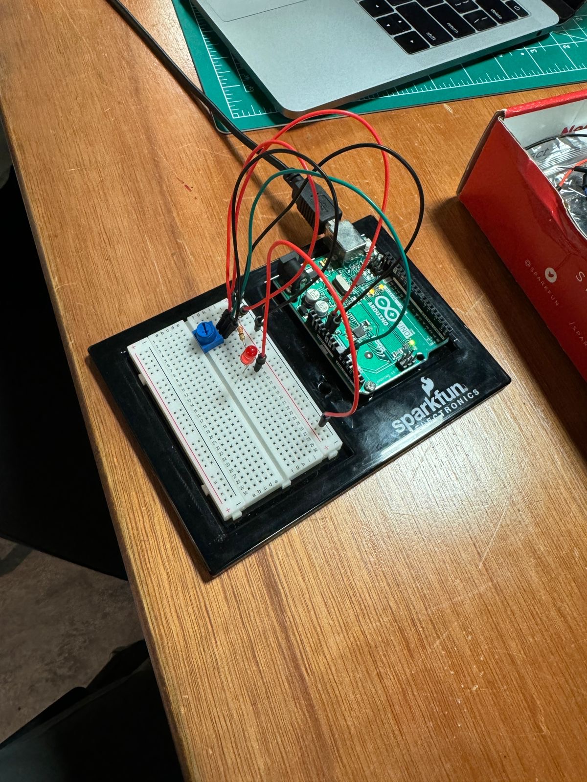
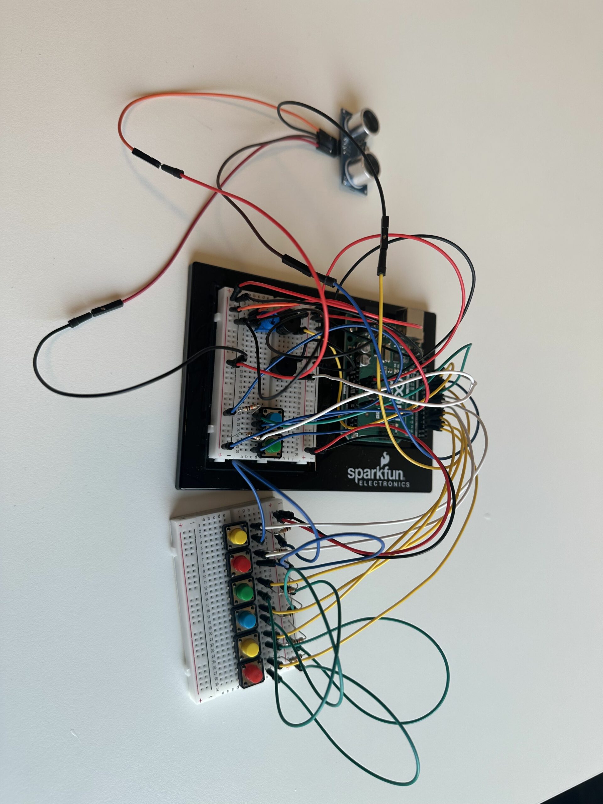
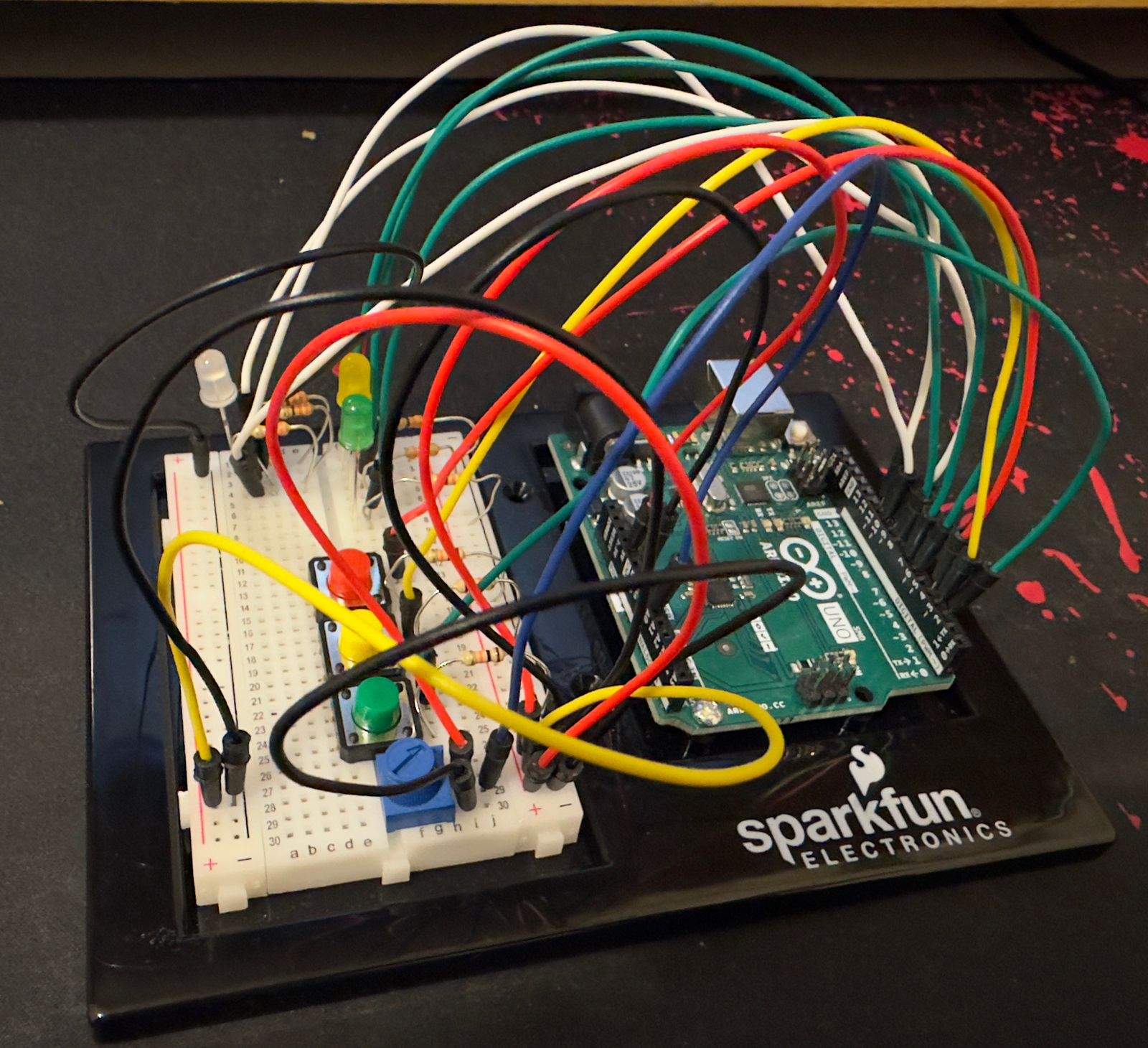
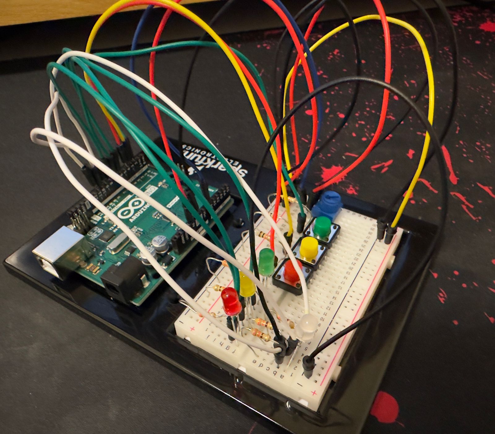
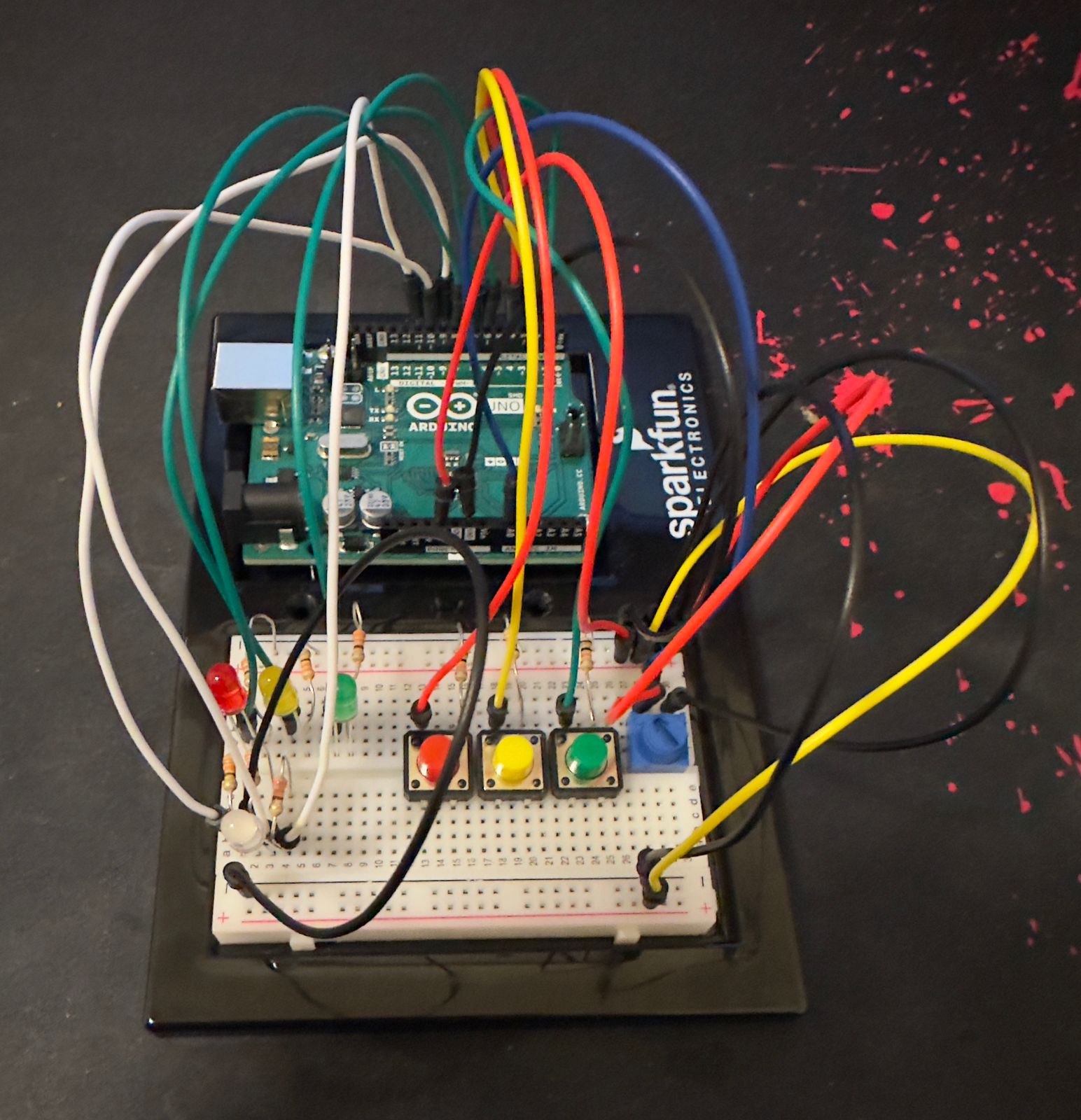
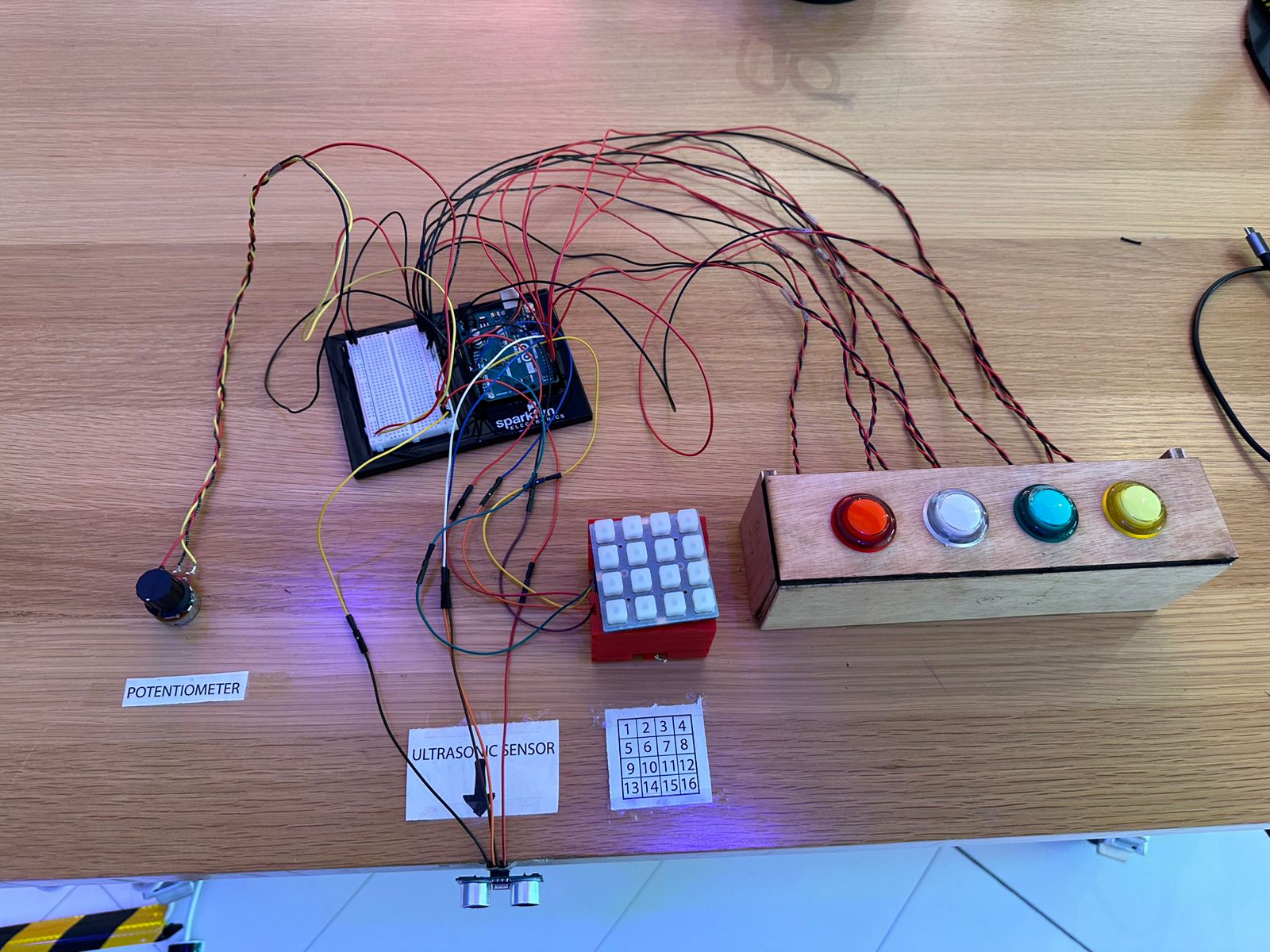
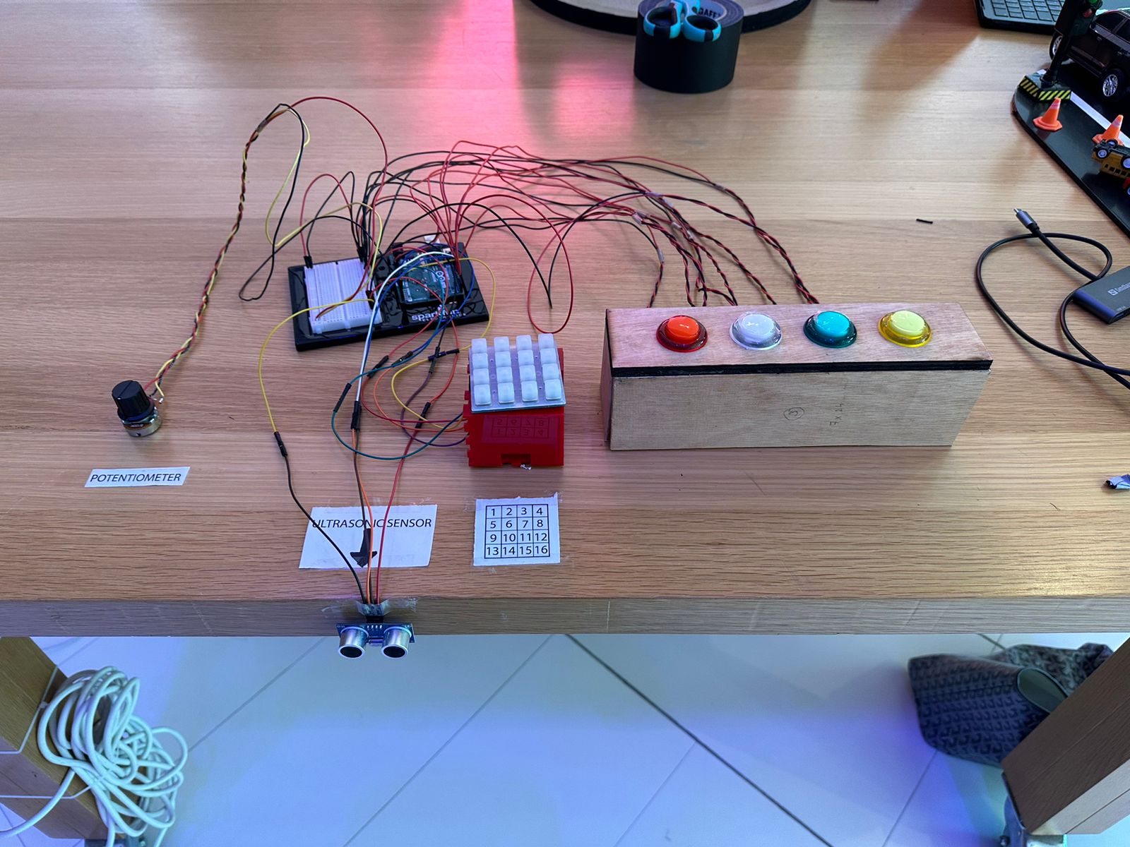
Players are presented with a physical board containing:

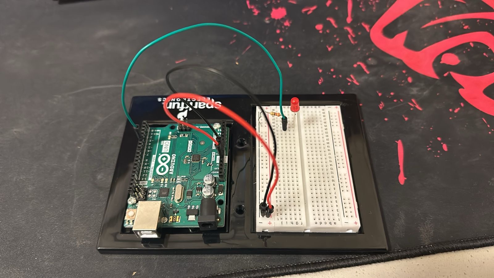
  • A series of buttons connected to LEDs that light up when pressed.
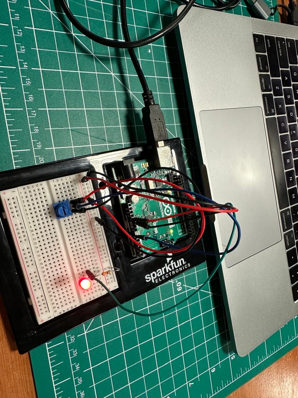
  • A potentiometer used to adjust resistance values.
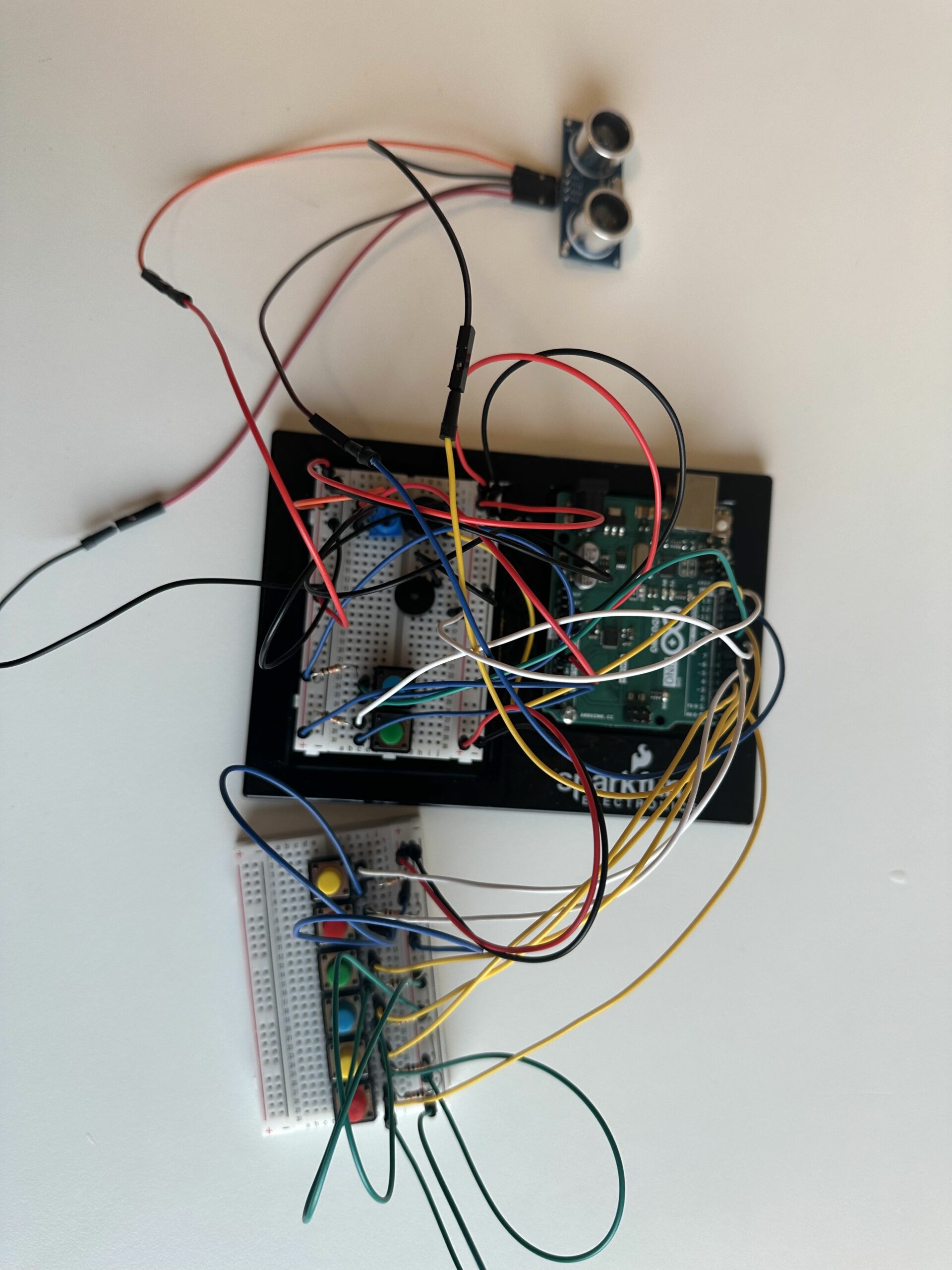
  • An ultrasonic distance sensor to measure and input distances.
  • A keypad for code entry.

The p5.js interface displays:

  • Task instructions and success criteria.
  • A visual representation of the “bomb,” including a countdown timer.
  • Feedback sections that show task outcomes and game progress.

Game Flow

The game progresses through a series of tasks such as adjusting distances, matching potentiometer values, entering sequences through buttons, and inputting codes on a keypad. Each task completion is visually indicated, moving the player closer to defusing the bomb.

Implementation

Hardware Components

  • Buttons and LEDs: Create a direct interaction where pressing a button shows immediate visual feedback through an LED.
  • Potentiometer: Adjusts to match a required voltage displayed on the p5.js interface.
  • Ultrasonic Sensor: Measures how far away a player is from the sensor, requiring players to physically move to match the required distance.
  • Adafruit Trellis Keypad: Create a direct interaction where pressing a button shows immediate visual feedback through an LED.

Software Components

  • p5.js Visuals: Animates tasks, displays real-time data, and provides a graphical countdown timer and game status.
  • Serial Communication: Handles data transmission between the Arduino and the p5.js interface, using serial commands to start tasks and send results.

Interaction Design

The interaction design focuses on integrating tactile and visual feedback to enhance engagement:

  • Tactile: Feeling the buttons click and adjusting the potentiometer gives a hands-on experience.
  • Visual: Immediate updates on the interface when tasks are completed successfully or fail.

Communication Between Arduino and p5.js

The communication protocol is straightforward:

  • Sending Commands: p5.js sends numeric codes corresponding to different tasks.
  • Receiving Data: Arduino sends back results as comma-separated strings that p5.js parses and uses to update the game state.

Arduino

The Arduino sketch controls every hardware-related action that’s essential to gameplay. this sketch is designed to track inputs from a variety of sensors, including buttons via digital pins, potentiometers, adafruit trellis, and ultrasonic distance sensors. In order to guarantee accurate input detection, it manages button debouncing. It also regulates outputs, such as button and keypad LEDs, to give the player real-time feedback depending on the logic and status of the game.

For each cycle of the loop() function, the sketch checks the status of connected devices, updates the game state based on player interactions, and sends crucial gameplay data to the p5.js application over serial communication. This includes values like distance measurements, potentiometer levels, button sequence inputs, and keypad inputs, which are vital for progressing through the game’s challenges.

Code

#include <string.h>

// Define task states using an enum
enum Task {
  TASK_DISTANCE_SENSING,
  TASK_POTENTIOMETER_ADJUSTMENT,
  TASK_BUTTON_SEQUENCE,
  TASK_ADAFRUIT_KEYPAD,
  TASK_DEFUSED_SOUND,
  TASK_EXPLODED_SOUND
};

// Variables to store the current task and sensor values
volatile Task currentTask = TASK_DISTANCE_SENSING;
const int buttonPins[] = { 2, 3, 4, 5 };  // Pins for buttons
const int LEDpins[] = {10, 11, 12, 13}; // Pins for LED buttons
const int potPin = A0;
const int trigPin = 6; 
const int echoPin = 7;

// Variables to store sensor data
bool buttonStates[4] = { 0 };
int potValue = 0;
int distance = 0;

// Length of the button press sequence
const int sequenceLength = 5;   
// Array to store the button sequence     
int buttonSequence[sequenceLength]; 
// Index to keep track of the current position in the sequence 
int sequenceIndex = 0;               
bool lastButtonState[4] = { LOW, LOW, LOW, LOW };

String taskCommand = "0";
int taskNumber = 0;
// Initialize an empty string to hold the sequence
String sequenceString = "";  

#include <Wire.h>
#include "Adafruit_Trellis.h"

#define MOMENTARY 0
#define LATCHING 1
// set the mode here
#define MODE MOMENTARY

Adafruit_Trellis matrix0 = Adafruit_Trellis();
Adafruit_TrellisSet trellis = Adafruit_TrellisSet(&matrix0);

#define NUMTRELLIS 1

#define numKeys (NUMTRELLIS * 16)

#define INTPIN A2

int passcode[5];
int passcodeIndex = 0;
// Initialize an empty string for the passcode
String passcodeString = "";  

void setup() {
  Serial.begin(9600);  
  pinMode(trigPin, OUTPUT);
  pinMode(echoPin, INPUT);
  for (int i = 0; i < 4; i++) {
    // Set button pins with internal pull-up resistors
    pinMode(buttonPins[i], INPUT_PULLUP);  
    pinMode(LEDpins[i], OUTPUT);
  }
  pinMode(buzzerPin, OUTPUT);
  pinMode(INTPIN, INPUT);
  digitalWrite(INTPIN, HIGH);
  trellis.begin(0x70);
  // light up all the LEDs in order
  for (uint8_t i = 0; i < numKeys; i++) {
    trellis.setLED(i);
    trellis.writeDisplay();
    delay(50);
  }
  // then turn them off
  for (uint8_t i = 0; i < numKeys; i++) {
    trellis.clrLED(i);
    trellis.writeDisplay();
    delay(50);
  }
}


void loop() {
  if (Serial.available() > 0) {
    // Read the next command until a newline character
    taskCommand = Serial.readStringUntil('\n');  
    if (taskCommand.length() > 0) {
      taskNumber = taskCommand.toInt();
      if (taskNumber == 0 || taskNumber == 1 || taskNumber == 2) {
        currentTask = TASK_DISTANCE_SENSING;
      } else if (taskNumber == 3 || taskNumber == 4 || taskNumber == 5) {
        currentTask = TASK_POTENTIOMETER_ADJUSTMENT;
      } else if (taskNumber == 6) {
        currentTask = TASK_BUTTON_SEQUENCE;
      } else if (taskNumber == 7) {
        currentTask = TASK_ADAFRUIT_KEYPAD;
      } else {
        currentTask = static_cast<Task>(taskNumber);  
      }
      // Function to execute tasks
      executeTask(currentTask); 
    }
  }
}

void executeTask(Task task) {
  switch (task) {
    case TASK_DISTANCE_SENSING:
      distance = measureDistance();
      Serial.println(distance);
      break;
    case TASK_POTENTIOMETER_ADJUSTMENT:
      potValue = analogRead(potPin);
      Serial.println(potValue);
      break;
    case TASK_BUTTON_SEQUENCE:
      readButtons();
      break;
    case TASK_ADAFRUIT_KEYPAD:
      readKeypad();
      break;
    default:
      break;
  }
}


// Function to measure distance using an ultrasonic sensor
int measureDistance() {
  digitalWrite(trigPin, LOW);
  delayMicroseconds(2);
  digitalWrite(trigPin, HIGH);
  delayMicroseconds(10);
  digitalWrite(trigPin, LOW);
  // 38ms timeout for a max distance
  long duration = pulseIn(echoPin, HIGH, 38000);  
  // Calculate and return the distance
  return duration * 0.034 / 2;                    
}

// Function to read and report button states
void readButtons() {
  for (int i = 0; i < 4; i++) {
    // Invert because INPUT_PULLUP
    bool currentButtonState = !digitalRead(buttonPins[i]);  

    digitalWrite(LEDpins[i], currentButtonState ? HIGH : LOW);

    // Check if there is a change and the button is pressed
    if (currentButtonState && currentButtonState != lastButtonState[i] && sequenceIndex < sequenceLength) {
      // Store button number (1-based index)
      buttonSequence[sequenceIndex] = i + 1;  
      if (sequenceIndex > 0) {
        sequenceString += ",";  
      }
      // Add the button number to the string
      sequenceString += String(buttonSequence[sequenceIndex]);  
      sequenceIndex++;
    }

    // Update the last button state
    lastButtonState[i] = currentButtonState;
  }

  // Check if the sequence is complete
  if (sequenceIndex == sequenceLength) {
    // Send the complete sequence string
    Serial.println(sequenceString);  
    sequenceString = "";
    // Reset the sequence index to start new sequence capture
    sequenceIndex = 0;
  }
}

void readKeypad() {
  // 30ms delay is required, don't remove me!
  delay(30);  

  if (MODE == MOMENTARY) {
    // If a button was just pressed or released...
    if (trellis.readSwitches()) {

      // Go through every button
      for (uint8_t i = 0; i < numKeys; i++) {
        // If it was pressed, turn it on
        if (trellis.justPressed(i)) {
          trellis.setLED(i);
          trellis.writeDisplay();

          if (passcodeIndex < 5) {
            passcode[passcodeIndex] = i+1;
            if (passcodeIndex > 0) {
              passcodeString += ","; 
            }
            // Add the key index to the string
            passcodeString += String(passcode[passcodeIndex]);  
            passcodeIndex++;
          }

          // If it was released, turn it off
          if (trellis.justReleased(i)) {
            trellis.clrLED(i);
            trellis.writeDisplay();
          }
        }
      }

      // Check if the passcode is complete
      if (passcodeIndex == 5) {
        // Send the complete passcode string
        Serial.println(passcodeString); 
        // Reset for next input 
        passcodeString = "";
        passcodeIndex = 0;  
      }
    }
  }
}

P5.js

The p5.js sketch is crafted to enrich the player’s experience with engaging visuals and responsive game dynamics. It visually represents the game state on a web interface, animating elements like timers, sensor data displays, and game status messages. This sketch plays a critical role in bridging the physical and digital aspects of the game by interpreting and displaying data received from the Arduino.

The sketch manages different game states, such as starting the game, transitioning between tasks, and handling win-or-lose conditions. Each state is visually distinct and designed to keep the player informed and engaged.

Code

Points of Pride

  • One of the aspects I’m particularly proud of is the seamless integration and synchronization between the Arduino and p5.js environments, which facilitated a dynamic and interactive experience.
  • The development of the narrative-driven game logic within p5.js, which utilized the sensor inputs from Arduino to unfold a storyline, is another high point. This narrative approach significantly enhanced user engagement, making the technical aspects of the project more relatable and enjoyable.
  • The use of creative riddles that required players to interpret clues and respond with physical interactions, such as adjusting distances and entering sequences, added an educational layer that subtly introduced users to concepts of measurement, spatial awareness, and logical sequencing.
  • Despite not initially being confident in my soldering skills, I successfully soldered numerous components, and they functioned perfectly. This experience not only enhanced my abilities but also boosted my confidence, affirming that I am now proficient in soldering.

Video(Before the Showcase)

Video(During the showcase)

Future Improvements

  • Interactivity Enhancements: One exciting direction for future development is enhancing the game’s interactivity by introducing multiplayer features. This could involve allowing multiple players to interact with the same game setup simultaneously, adding a competitive element by having players complete tasks in sequence, against a timer, or against each other.
  • Leaderboard/Scoreboard: Integrating score tracking could significantly extend the game’s appeal and replayability. A leaderboard system where players can register their scores and compare them with other players.

Final Project – User Testing

Strengths of the Project

Users understood the relationship between their actions and the game responses well. This was particularly true for tasks involving direct interactions like pressing buttons.

  • Engagement with Tasks: The distance sensing tasks were well-received, as participants found them to be intuitive and fun.
  • Sensor Integration: The integration of the potentiometer within the game mechanics worked smoothly, providing a satisfying challenge to the players.

Areas for Improvement

  • Animation Speed: There was a noticeable slowdown in animation frames as the game progressed, which affected the overall experience. This issue needs to be addressed to ensure smooth gameplay.
  • Keypad Usage: Although the Adafruit Trellis keypad was a central component of the game, many users needed additional instructions to use it effectively.

Enhancements and Future Steps

To make the game more user-friendly and engaging, here are some steps I plan to take based on the feedback:

  • Clarify Sensor Usage: Simplify the riddles associated with sensors or provide clearer, step-by-step tutorials that guide the users on how to interact with the game.
  • Improve Animations: Optimize the code to ensure that animation frames run smoothly throughout the game, enhancing the visual feedback that is crucial for interactive gameplay.

Video for 1st user test/feedback

Video for 2nd user test/feedback

Week 12: Khalifa Alshamsi, Snehil Ahuja, and Saeed Lootah

  1. Make something that uses only one sensor  on Arduino and makes the ellipse in p5 move on the horizontal axis, in the middle of the screen, and nothing on Arduino is controlled by p5
  2. Make something that controls the LED brightness from p5

For these two exercises, we made it so that the potentiometer that is connected to the Arduino controls the LED on the breadboard and the ellipse in the p5 sketch in the middle of the screen, and also when the keyboard keys are pressed up or down it would change the brightness of that LED light.

P5.js Code:

let LEDbrightness = 0;

function setup()
{
  createCanvas(400, 400);
}


function textDisplay() //display text in the starting
{
  text("PRESS SPACE TO START SERIAL PORT", width/2 - 109, height/2 - 5);
}

function draw()
{

  background(255);

  if (serialActive) //if serial is active
  {
    text("CONNECTED", width/2 - 27, height/2 - 5);
    text("PRESS UP/DOWN ARROW KEYS TO CHANGE BRIGHTNESS!", width/2 -180, height/2 + 15);
  }
  else
  {
    textDisplay();
  }
}


function keyPressed() //built in function
{
  if (key == " ") //if space is pressed then
  {
    setUpSerial(); //setup the serial
  }
  else if (keyCode == DOWN_ARROW)
  {
    if (LEDbrightness != 0)
    {
      LEDbrightness = LEDbrightness - 20;
    }
  }
  else if (keyCode == UP_ARROW)
  {
    if (LEDbrightness != 250)
    {
      LEDbrightness = LEDbrightness + 20;
    }
  }

}

//callback function
function readSerial(data)
{
    let sendToArduino = LEDbrightness + "\n"; //add the next line to dimness counter
    writeSerial(sendToArduino); //write serial and send to arduino
}

Arduino Code:

const int LED_PIN = 5;
int brightness = 0;

void setup()
{
  Serial.begin(9600);

  pinMode(LED_PIN, OUTPUT);

  while (Serial.available() <= 0)
  {
    Serial.println("CONNECTION STARTED");
  }
}
void loop()
{

    while (Serial.available())
    {
      brightness = Serial.parseInt();
      Serial.println(brightness);

      if (Serial.read() == '\n')
      {
        analogWrite(LED_PIN, brightness);
      }
    }
}

Video and Photos for Exercise 1:

For exercise 1, since we were just getting started, the main problem was understanding how serial communication works. We had some kind of idea when it was being presented to us, but until we started working, we didn’t really know. Other than that, there weren’t really any specific challenges. We didn’t need to use the trim() method, we had one value coming in from the Arduino, which was the potentiometer, and we had some troubles at first, but once we casted it as an integer value (it’s received as a string), then mapped it to the width and made the mapped value the x-position of the ellipse the project was done.

You’ll notice in the image that there’s an LED. The LED was there to test whether or not there was power being outputted from the potentiometer. We added it while we were debugging.

Video and Photos for Exercise 2:

Like the previous exercise there was only one value that was being communicated between the arduino and the p5js code so it was fairly simple. The hard part was just getting it such that tapping it reduced the brightness value by a specific amount and increasing it by a certain amount.

3. Take the gravity wind example and make it so every time the ball bounces one led lights up and then turns off, and you can control the wind from one analog sensor

For this exercise, the code creation uses p5, where physics principles like gravity and wind influence the ellipse’s motion. The sketch also communicates with the Arduino, which can control an LED based on the object’s motion, specifically if it bounces.

P5.js Code:

let dragForce = 0.99;
let mass = 20;
let ledState = 0;
let velocity;
let gravity;
let position;
let acceleration;
let wind;
let force;
let bounced = false;


function setup() {
  createCanvas(640, 480);
  textSize(18);
  position = createVector(width / 2, 0);
  velocity = createVector(0, 0);
  acceleration = createVector(0, 0);
  gravity = createVector(0, 0.3 * mass);
  wind = createVector(0, 0);
}

function draw() {
  background(0,40);
  // background(0);
  // background(255);

  if (!serialActive) {
    fill(255);
    text("Press Space Bar to select Serial Port", 20, 30);
  } else {

    noStroke();
    force = p5.Vector.div(wind, mass);
    acceleration.add(force);
    force = 0;
    force = p5.Vector.div(gravity, mass);
    acceleration.add(force);
    force = 0;
    velocity.add(acceleration);
    velocity.mult(dragForce);
    position.add(velocity);
    acceleration.mult(0);

    ellipse(position.x, position.y, mass, mass);
    if (position.y > (height - mass / 2)-30 ) {
      velocity.y *= -0.9;
      position.y = (height - mass / 2)-30;
      ledState= 1;
      
      if (!bounced) {
        fill(255, 0, 0); // Red when just bounced
        bounced = true; // Update bounce state
      } else {
        fill(255); // White otherwise
        bounced = false; // Reset bounce state
      }
    } else {
      ledState = 0;
    }
  
    
  }

  rect(0,height-30,width,30);
  
}

function keyPressed() {
  if (key == " ") {
    // important to have in order to start the serial connection!!
    setUpSerial();
  }
}

function readSerial(data) {
  if (data != null) {
    // make sure there is actually a message
    // split the message
    let fromArduino = split(trim(data), ",");
    // if the right length, then proceed
    if (fromArduino.length == 1) {
      let windCurrent = int(fromArduino[0]);
      wind.x = map(windCurrent, 0, 1023, -1, 1);
    }

    //////////////////////////////////
    //SEND TO ARDUINO HERE (handshake)
    //////////////////////////////////
    let sendToArduino = ledState + "\n";
    writeSerial(sendToArduino);
  }
}

Arduino code:

int ledPin = 5;
int potPin = A0;

void setup() {
  Serial.begin(9600);

  pinMode(LED_BUILTIN, OUTPUT);

  // Outputs on these pins
  pinMode(ledPin, OUTPUT);

  // start the handshake
  while (Serial.available() <= 0) {
    digitalWrite(LED_BUILTIN, HIGH); // on/blink while waiting for serial data
    Serial.println("0"); // send a starting message
    delay(300);            // wait 1/3 second
    digitalWrite(LED_BUILTIN, LOW);
    delay(50);
  }
}

void loop() {
  // wait for data from p5 before doing something
  while (Serial.available()) {
    digitalWrite(LED_BUILTIN, HIGH); // led on while receiving data

    int right = Serial.parseInt();
    if (Serial.read() == '\n') {
      digitalWrite(ledPin, right);
      int potValue = analogRead(potPin);
      delay(5);
      Serial.println(potValue);
    }
  }
}

Video and Photos for Exercise 3:

Understandably, this was the hardest of the 3. We first manipulated the code given to us (which had the wind and ball code). We changed the wind global variable in much the same way as the first exercise: The potentiometer value was mapped to the wind variable. The hard part was the bouncing. There was a point during the exercise where we felt we had written everything correctly, and after going through the code together, we couldn’t see what was wrong. We made a variable called bounced and had it such that inside of the if statement, which would be called upon when the ball was supposed to bounce, the variable would be the opposite of what it was previously (if true then false, if its false then true). We then realized we were initializing the bounced variable inside of the draw function. We made it a global variable, and then it worked.

Week 12: Final Project – Defuse Dash

Bomb Defusal Game: Defuse Dash

Concept

The bomb defusal game is an interactive physical and digital game where players must complete a series of tasks using a combination of hardware components and a computer interface to “defuse” an Arduino bomb within a set time limit. Each task involves different components such as buttons, a potentiometer, and an ultrasonic sensor, providing a variety of challenges that test the player’s reaction speed, precision, and problem-solving skills.

Responsibilities

  • P5.js
    • Visual Display: Renders the game interface, including task instructions, status updates, and timers.
    • User Interaction: Processes and displays inputs received from the Arduino, allowing players to see the results of their actions in real time.
    • Game Feedback: Provides immediate visual feedback based on player actions, such as changing colors or displaying messages to indicate success or failure.
  • Arduino
    • Input Reading: Collects and processes inputs from physical game controls (buttons, potentiometer, ultrasonic sensor).
    • Logic Handling: Executes the core game mechanics based on player interactions and sends the status to P5.js.
    • Output Control: Manages physical outputs like sounds (buzzer or servo) to enhance gameplay interaction.

Game Mechanics

Task-Based Gameplay: Players face multiple tasks that they must complete to defuse the bomb. Each task uses different components:

  • Button Presses: Used for tasks like code entry, where players must press the correct sequence of buttons.
  • Potentiometer Adjustments: This might involve setting a dial to match a specific level displayed on the P5.js interface.
  • Ultrasonic Sensor: Requires players to move an object to the correct distance from the sensor as shown by the computer interface.
  • LEDs: Used to provide visual feedback on task status (e.g., success, warning, error). The Arduino controls these LEDs based on the game state and player inputs.
  • Piezo Speaker: Can emit different tones or alerts based on game events like task success, failure, or warnings.

Time Limit: The game is timed, adding pressure and requiring quick thinking and fast responses. Failing to complete tasks within the time limit results in a game-over scenario.

Current Progress

  • Circuit Setup: Configured a basic circuit with 2 buttons, 1 potentiometer, and 1 ultrasonic sensor connected to an Arduino Uno.
  • Arduino Programming: Developed code to read inputs from the hardware components and send this data to the P5.js application via serial communication.
  • P5.js Programming: Set up a P5.js sketch to receive data from Arduino and visually display game elements such as task instructions, player inputs, and a timer.

Week 12: Reading Response

The reading “Design Meets Disability” explores the relationship between beautiful design and practical usability while arguing for a change in perceptions of the design of items intended for people with disabilities.

The growth of eyeglasses from a stigmatized medical device to a stylish accessory demonstrates how design has the ability to alter views. In the past, glasses were frequently associated with social shame and were only considered useful instruments for correcting vision. But by adding fashion components to its designs, eyewear has evolved into an item that is for use and visual appeal.

Aimee Mullins, a model and athlete, has demonstrated how creatively she uses prosthetic limbs to emphasize the need for cross-disciplinary collaboration between fashion designers and disability product designers. Her prostheses, which are both artistically beautiful and practical, are a prime example of how incorporating fashion into disability design can defy stereotypes and turn medical devices into fashion statements.

Is it possible for the aesthetics of assistive devices to impact how society views and treats people with disabilities? If yes, how can designers use this authority to promote greater acceptance and inclusion?

Week 11: Final Project Concept

Overview

For my final project, I am thinking of making a game where players are presented with a series of electronic puzzles that increase in complexity.
Each puzzle requires players to assemble components on a breadboard within a set time limit. The game provides immediate feedback on their solutions, and players earn points based on speed and accuracy.

Arduino

Breadboard where players will plug in various electronic components like resistors, wires, buzzers, or other sensors.
I would require some kind of sensors that would verify whether components are correctly placed and circuits are properly completed on the breadboard.

If Possible
Optionally, include buttons or switches on the board for starting the timer, resetting the puzzle, or requesting hints.

Processing

Processing will display each puzzle diagram on a screen, track the time remaining, and handle the transition between different puzzles.
Immediately inform players whether the circuit is correct. If incorrect, highlight errors or provide hints, depending on the game mode.
A scoring algorithm based on the complexity of the puzzle, the accuracy of the completed circuit, and the speed of completion.

Week 11: Digital Piano with Distance-Sensing Percussions

Concept

The Digital Piano with Distance-Sensing Percussions is an innovative musical instrument that blends traditional piano elements with modern sensor technology to create a unique and interactive musical experience. This project utilizes an array of digital push buttons connected to an Arduino board to simulate a piano keyboard, where each button triggers a distinct musical note. In addition to the conventional keyboard setup, the instrument incorporates an ultrasonic distance sensor, which introduces a dynamic layer of percussion sounds. These sounds vary depending on the distance of the player’s hand. Furthermore, a potentiometer is integrated to alter the pitch of the notes dynamically, offering musicians the ability to manipulate the sound palette expressively.

Images

Components Used

  1. Arduino Uno
  2. Breadboard (x2)
  3. Jumper Wires
  4. Piezo Buzzer (x2)
  5. Push Buttons (x8)
  6. Potentiometer
  7. 10k ohm resistors (x8)
  8. Ultrasonic Sensor

Circuit Setup

Power Connections

      • Arduino 5V to Breadboard positive rail
      • Arduino GND to Breadboard negative rail

Piezo Buzzers

    • Piezo Buzzer 1:
      • Positive connection to Arduino digital pin 12
      • Negative connection to Breadboard negative rail
    • Piezo Buzzer 2:
      • Positive connection to Arduino digital pin 13
      • Negative connection to Breadboard negative rail

Push Buttons

      • One side of each button connected to the Breadboard positive rail
      • The other side of each button is connected through a 10k ohm resistor to the Breadboard negative rail and also connected to Arduino digital pins 2 through 9.

Potentiometer

      • One outer pin is connected to the Breadboard positive rail.
      • Another outer pin is connected to the Breadboard negative rail.
      • Middle pin connected to Arduino analog pin A0.

Ultrasonic Sensor

      • VCC pin is connected to the Breadboard positive rail.
      • GND pin is connected to the Breadboard negative rail.
      • TRIG pin is connected to Arduino digital pin 10.
      • ECHO pin is connected to Arduino digital pin 11.

Video

Code

int buzzerPin = 12;
int buzzer2 = 13;
int potPin = A0;
int keys[] = {2, 3, 4, 5, 6, 7, 8, 9};
// Frequencies for notes (C4 to C5)
int notes[] = {262, 294, 330, 349, 392, 440, 494, 523}; 
int trigPin = 10;
int echoPin = 11;
int bassDrum = 200; 
int snare = 250; 
int hiHat = 300;


void setup() {
  pinMode(buzzerPin, OUTPUT);
  pinMode(buzzer2,OUTPUT);
  pinMode(2,INPUT);
  pinMode(3,INPUT);
  pinMode(4,INPUT);
  pinMode(5,INPUT);
  pinMode(6,INPUT);
  pinMode(7,INPUT);
  pinMode(8,INPUT);
  pinMode(9,INPUT);
  pinMode(trigPin, OUTPUT);
  pinMode(echoPin, INPUT);
  Serial.begin(9600);
}

void loop() {
  int potValue = analogRead(potPin);
  int volume = map(potValue, 0, 1023, 0, 255); // Map the potentiometer value to a volume range

  // Measure distance using the ultrasonic sensor
  digitalWrite(trigPin, LOW);
  delayMicroseconds(2);
  digitalWrite(trigPin, HIGH);
  delayMicroseconds(10);
  digitalWrite(trigPin, LOW);
  long duration = pulseIn(echoPin, HIGH);
  int distance = duration * 0.034 / 2; // Calculate the distance

  Serial.print(distance);
  Serial.println(" cm");


  bool isAnyButtonPressed = false;
  for (int i = 0; i < 8; i++) {
    int modifiedNote = map(potValue, 0, 1023, notes[i] / 2, notes[i] * 2);
      if (digitalRead(keys[i]) == HIGH) {
          tone(buzzerPin, modifiedNote, 100);
          isAnyButtonPressed = true;
          break; // Stop the loop once a button is found pressed
      }
  }

  if (!isAnyButtonPressed) {
    noTone(buzzerPin);
  }
  if (distance < 10) {
    tone(buzzer2, bassDrum, 100);
  } else if (distance >= 10 && distance < 20) {
    tone(buzzer2, snare, 100);
  } else if (distance >= 20 && distance < 30) {
    tone(buzzer2, hiHat, 100);
  } else {
    noTone(buzzer2);
  }
    delay(100);
}

In the loop, the program first reads the potentiometer value and uses it to modify the frequency of the piano notes. Depending on the button pressed, it plays a modified note frequency. If no buttons are pressed, it stops any ongoing tone. Depending on the distance detected, it chooses a percussion sound to play, simulating a drum kit with different sounds for different ranges.

Week 11: Reading Reponse

This week’s reading advocates for a more holistic approach to interaction design, one that fully engages human capabilities. The author criticizes current interfaces (i.e., touchscreens) for ignoring the full range of human hand functions—particularly our ability to feel textures and manipulate objects. Victor’s criticism of using just one finger made me wonder: if we could accomplish so much with just one finger, how many more opportunities might arise if we used our entire body? However, this also makes me that there is some level of bias because the author formerly worked in interaction design, I wonder if their strong opinions are a result of this experience.

Although I agree with the author’s perception that we can accomplish more with the use of our hands, what about the people who aren’t able to use them? “Picture under glass” is far more accessible than previous interactive designs since it makes use of touch and drag, which is perhaps one of the simplest human movements.

Furthermore, although more natural behaviors like grabbing and throwing are being incorporated into virtual reality systems, these systems are still mostly dependent on visual inputs and are unable to provide true haptic feedback due to limitations in existing technology. This makes me wonder what are innovative ways that technology can simulate these experiences without reverting to traditional physical forms?

Week 10: Glow Rush Game

Concept

This week, I set out to blend analog and digital elements into a single creative project, leading me to design a reaction game inspired by the “reaction lights” game by Lummic I stumbled upon a few months ago. In this game, players test their reflexes by pressing a button as soon as its corresponding light turns on.

I integrated a tricolor RGB light that serves as a real-time indicator of the player’s reaction time—green signals excellent speed, blue is moderate, and red denotes a slower response. To add a twist and enhance engagement, I included a potentiometer to adjust the game’s difficulty, effectively changing the time intervals that define the three color responses. This setup not only challenges players but also gives them control over the complexity of the task, making each round adaptable and uniquely challenging.

Images


Components Used

  1. Arduino Uno
  2. Tricolor RGB LED
  3. Pushbuttons (3)
  4. Resistors:
    1. 330 ohm resistors (3)
    2. 10k ohm resistors (3)
  5. Potentiometer
  6. Breadboard
  7. Jumper Wires

Circuit Setup

  1. RGB LED
    • The common cathode of the RGB LED connects to the Arduino’s ground.
      The red, green, and blue anodes are connected to PWM-capable digital pins (9, 10, and 11) through 330-ohm resistors to limit current.
  2. Pushbuttons
    • Each button is connected to one of the digital input pins (2, 3, and 4).
      The other side of each button is linked to the ground through a 10k-ohm resistor to ensure the pin reads LOW when the button is unpressed.
  3. Potentiometer
    • One outer pin connects to the 5V on the Arduino, and the other to the ground. The middle wiper pin is connected to analog input A0, allowing the Arduino to read varying voltage levels as the potentiometer is adjusted.

Video

Code

void setup() {
  for (int i = 0; i < 3; i++) {
    pinMode(buttonPins[i], INPUT_PULLUP);
    pinMode(ledPins[i], OUTPUT);
  }

  // Set up RGB LED pins as outputs
  pinMode(redPin, OUTPUT);
  pinMode(greenPin, OUTPUT);
  pinMode(bluePin, OUTPUT);

  Serial.begin(9600);
}


Input pins (buttonPins): Configured with INPUT_PULLUP to use the internal pull-up resistors, ideal for buttons.
Output pins (ledPins and RGB LED pins): Set as outputs to control LEDs.

void loop() {
  int potValue = analogRead(potPin); 
  // Adjust the max delay range for more sensitivity
  int maxDelay = map(potValue, 0, 1023, 5000, 2000); 
  Serial.print("Potentiometer Value: ");
  Serial.print(potValue);
  Serial.print(", Max Delay (ms): ");
  Serial.println(maxDelay);

  if (!gameActive) {
    gameActive = true;
    targetLed = random(0, 3);
    digitalWrite(ledPins[targetLed], HIGH);
    startTime = millis();
    Serial.print("Game started, respond before ");
    Serial.print(maxDelay);
    Serial.println(" ms for the best score!");
  }

  if (digitalRead(buttonPins[targetLed]) == LOW) {
    // Debounce by ensuring at least 50 ms has passed
    if (millis() - startTime > 50) { 
      unsigned long reactionTime = millis() - startTime;
      Serial.print("Reaction Time: ");
      Serial.println(reactionTime);

      setColorFromReactionTime(reactionTime, maxDelay);
      // Show result for 1 second
      delay(1000); 
      // Turn off RGB LED
      setColor(0, 0, 0); 
      digitalWrite(ledPins[targetLed], LOW);
      gameActive = false;
      delay(1000); 
    }
  }
}

There are 3 main steps in the loop function:

  1. Read Potentiometer: Determines the difficulty level by reading the potPin and mapping its value to define maxDelay, the maximum time allowed for a response.
  2. Game Control
    1. If gameActive is false, the game starts by picking a random LED to light up and marks the start time.
    2. If the corresponding button is pressed (digitalRead(buttonPins[targetLed]) == LOW), it checks for debouncing (to ensure the button press is genuine) and then calculates the reaction time.
  3. Serial Output: Outputs debug information such as potentiometer value and maximum delay time to the serial monitor.
void setColorFromReactionTime(unsigned long reactionTime, int maxDelay) {
  // Set RGB LED color based on reaction time as a fraction of maxDelay
  if (reactionTime < maxDelay / 5) {
    // Fast: Green
    setColor(0, 255, 0); 
  } else if (reactionTime < maxDelay / 2) {
    // Moderate: Blue
    setColor(0, 0, 255); 
  } else {
    // Slow: Red
    setColor(255, 0, 0); 
  }
}

It is based on the player’s reaction time, this function sets the color of the RGB LED:

  • Fast Response: Less than 1/5 of maxDelay, the LED turns green.
  • Moderate Response: Less than 1/2 but more than 1/5 of maxDelay, it turns blue.
  • Slow Response: Slower than 1/2 of maxDelay, it turns red.

Week 10: Reading Response

The main focus of Tom Igoe’s perceptive essay is the change from the artist serving as the exclusive storyteller to acting as a facilitator. Artists have historically used their creations to directly communicate a message or an emotion. On the other hand, interactive art plays a transforming function, whereby the artwork acts as a catalyst for the audience’s discovery. I like this transition as this aligns with the tenets of user experience design, which emphasize empowering users to choose their paths rather than trying to control them.

In traditional art, viewers often interpret a piece based on the artist’s description and the experience they want to show their viewers. Interactive art, however, offers a different dynamic. Each interactive piece is a canvas for numerous personal narratives, evolving with every user interaction. Here, the artwork doesn’t present a fixed story; instead, it allows for a multitude of stories to emerge, each shaped by individual interactions. The artist sets the framework, but it’s the participants who create their unique narratives through their engagement with the piece.

This is evident in modern interactive installations like “Rain Room,” where the experience of walking through a rainstorm without getting wet engages visitors in a unique conversation with the elements. I feel that the development of virtual reality environments adheres to these same principles that Igoe is proving in his argument. VR creators set the stage for experiences, but it is ultimately the users, through their actions and decisions, who navigate and mold these virtual worlds.

The text even highlighted that the user must be given hints or basic information about the interactive art piece. However, this made me ponder how the balance between guiding the audience and allowing freedom shapes the outcome of interactive art. Can there be too much or too little of either?