Final Project Documentation – PhotoGhost. by Marcos Hernández

1. Concept

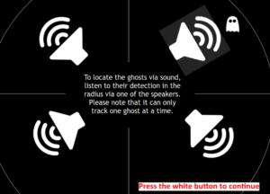
This is a game that seeks to provide engagement via the unknown. That is, a game that uses the concepts of darkness and ghosts. Take, for example, the video game series Five Nights at Freddy’s, whose gameplay loop consists in administrating the energy left in order to prevent the enemies from reaching the protagonist; PhotoGhost is almost the same. In this game, the player has to traverse a dark area that gets filled with ghosts over time, and in order to avoid losing, the player has to fill the battery by going to the battery refill areas. Also, as part of the core gameplay concept, the player can listen to some of the noises that the piezo buzzers make according to the location of the ghost.

PhotoGhost.  in fullscreen

2. Pictures of the project

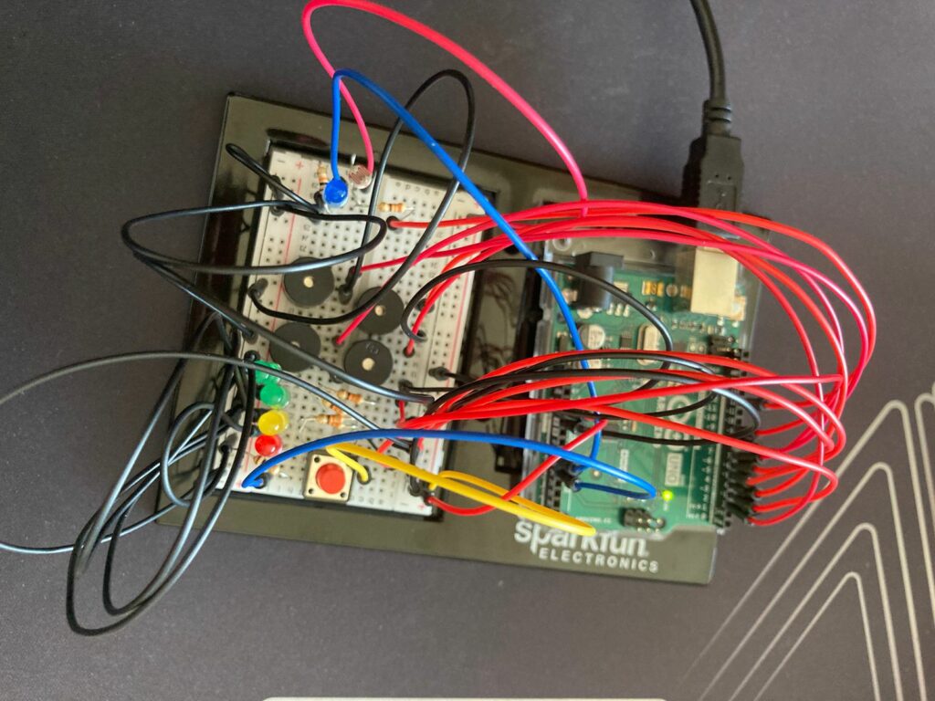
2.1 Picture of physical component
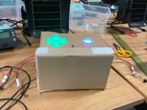
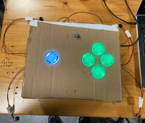
Figure 1. Physical component with cover on, while in development.
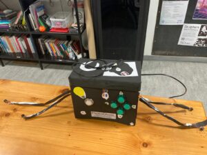
Figure 2. Physical component from a top perspective, while in development.
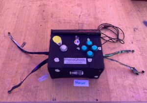
Figure 3. Box finished
Figure 4. Box Finished from a different perspective.
2.2 Pictures of the Arduino set-up
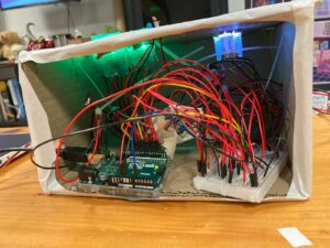
Figure 5. Arduino wiring complete, which is inside the box.
2.3 Pictures of the game in p5.js
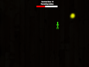
Figure 6. Tutorial
Figure 7. Gameplay, but the lights are turned off.
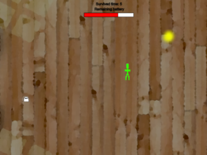
Figure 8. Gameplay, but the lights are turned ON and a ghost is visible.

3. Implementation

3.1. Interaction Design

When the player arrives at the controller, it will be observable that there are:

      • 4 Green buttons placed as a D-PAD.
      • One white button that is put further away from the rest of the components.
      • One photoresistor and one blue LED close to each other.
      • Four piezo buzzers that are coming on different sides: two on the left and two on the right. Each one is located on a different corner.
      • A hole where the data is sent to the Arduino.

While the visual design is rather basic, it seeks to be portable, easy to read, and comfortable to use.

3.2. Description of Arduino code

Since the Arduino code is too long, here is a link to it on my GitHub: PhotoGhost. Arduino Code

Basically, what the Arduino code does is the following:

      1. It prepares the assigned pins, and then it waits to receive the communication with p5.js.
      2. Once communication is established, it starts reading the inputs of the green buttons (movement) and the white button (for the flashlight) in binary to check which is being pressed. Also, it checks for the current value of the flashlight, the location of the enemy, the assigned piezo speaker, and some controls (currentflashlightstatus and flashlightcountdown) to avoid sending data when it is not needed.
      3. Once it receives data from p5.js, it checks where the enemy is according to the value sent to the piezo speakers and plays a tune to indicate to the player the current position of the enemy.
        if (SpiezoPinUL == 2) {
          tone(piezoPinUL, 500);
        } else if (SpiezoPinUL == 0) {
          noTone(piezoPinUL);
        }
        
        if (SpiezoPinUR == 2) {
          tone(piezoPinUR, 500);
        } else if (SpiezoPinUR == 0) {
          noTone(piezoPinUR);
        }
        
        if (SpiezoPinDL == 2) {
          tone(piezoPinDL, 500);
        } else if (SpiezoPinDL == 0) {
          noTone(piezoPinDL);
        }
        
        if (SpiezoPinDR == 2) {
          tone(piezoPinDR, 500);
        } else if (SpiezoPinDR == 0) {
          noTone(piezoPinDR);
        }
      4. If the player is currently standing in a flashlight recharger, it starts reading the data coming from the photoresistor; this is done in this way to avoid exploits. At the same time, a blue LED is turned on, indicating that the photoresistor is receiving data.
      5. When finished, the photoresistor stops sending data, the blue LED is turned off, and it sends all the processed data to p5.js.
        //I send you data and you send me more data!
        Serial.print(brightness);
        Serial.print(",");
        
        //Flashlight
        Serial.print(buttonFlashlight);
        Serial.print(",");
        
        //Movement
        Serial.print(move_up);
        Serial.print(",");
        Serial.print(move_left);
        Serial.print(",");
        Serial.print(move_down);
        Serial.print(",");
        Serial.println(move_right);
3.3. Description of p5.js code and embedded example

The p5.js implementation was tricky. Before explaining the code, here is an embedded version of it. In the same embedded file, you can find the code for it:

Keep in mind that due to not having the Arduino control, it is possilbe to use WASD to move, F to turn the light ON and OFF, and BACKSPACE to skip the serial port screen.

In the p5.js code, the following is happening:

      1. The game first checks where the player is at the moment, whether it be the menu, the game over screen, or the gameplay. This is to arrange the code for better readability.
        function draw() {
          if (gamestate == 0) {
            menu();
          } else if (gamestate == 1) {
            game();
          } else if (gamestate == 2) {
            credits();
          } else if (gamestate == 3) {
            gameover();
          }
        }
      2. The game first waits for the player to set up the Arduino connection in order to start receiving input. This part of the code is inside the class file Menu.js:
        display_mainmenu() {
            push();
            background(250);
            fill(0);
            textSize(60);
            text("PhotoGhost.", 240, 150);
            textSize(25);
            text("by Marcos Hernández", 280, 190);
            textSize(10);
            text(
              "I do not own any of the images and sounds in this game. They belong to the respective authors.",
              10,
              595
            );
            fill(200);
            noStroke();
            rect(300, 160, 230, 10);
            rect(570, 160, 10, 10);
            stroke(255);
            fill(0);
            textSize(30);
            if (!serialActive) {
              text("Press Space Bar to select serial port", 160, 400);
            } else {
              text("Press the white button to start", 200, 400);
            }
            pop();
          }
      3. Once the player finishes the tutorial by pressing the white button, they are immediately transported to the game. The timer starts, and every 60 frames, it adds a second, the flashlight battery gets reduced, and enemies are moved at set intervals. Also in this part, the game checks for multiple things, such as the random placement of the player, enemies, and the flashlight recharger. Here is an example of how it works with enemies:
        if (time == 0 && enemyspawnercontrol == 0) {
            enemyspawnercontrol = 1;
            while (spawningenemy == true) {
              xtospawn = int(random(30, width));
              ytospawn = int(random(30, height));
              if (
                (xtospawn < player.x - 20 || xtospawn > player.x + player.w + 20) &&
                (ytospawn < player.y - 20 || ytospawn > player.y + player.h + 20)
              ) {
                enemy = new Enemies(xtospawn, ytospawn, 20, 20);
                enemies.push(enemy); //Add into the list of enemies.
                break;
              } else {
                //Nothing, it repeats lol.
              }
            }
        
            //Spawn enemy every 15 seconds.
          } else if (time % 15 == 0 && enemyspawnercontrol == 0) {
            enemyspawnercontrol = 1;
            while (spawningenemy == true) {
              xtospawn = int(random(30, width));
              ytospawn = int(random(30, height));
              if (
                (xtospawn < player.x - 20 || xtospawn > player.x + player.w + 20) &&
                (ytospawn < player.y - 20 || ytospawn > player.y + player.h + 20)
              ) {
                enemy = new Enemies(xtospawn, ytospawn, 20, 20);
                enemies.push(enemy); //Add into the list of enemies.
                break;
              } else {
                //Nothing, it repeats lol.
              }
            }
        }

        In a short explanation, the game first checks that the time is zero to spawn the first enemy in a location far from the player. Notice that a while loop is employed in order to avoid the enemy spawning accidentally inside the player and ending the game. After that, the enemy is saved into the array and displayed in order to be seen when the flashlight is ON.

      4. The player hitbox is divided into four parts, in a squarely manner, to check where the ghosts (enemies) are in order to send the current position of the ghost to the Arduino to play the sound to the corresponding piezo buzzer:
        //Bottom right
            if (
              player.x + player.w * 5 > enemies[c].x &&
              player.x < enemies[c].x + enemies[c].w &&
              player.y + player.w * 5 > enemies[c].y &&
              player.y < enemies[c].y + enemies[c].w
            ) {
              SpiezoPinDR = 2;
              //print("FAR: Collision with bottom right.");
            }
        
            //Bottom left
            if (
              player.x - player.w * 5 + player.w * 5 > enemies[c].x &&
              player.x - player.w * 5 < enemies[c].x + enemies[c].w &&
              player.y + player.w * 5 > enemies[c].y &&
              player.y < enemies[c].y + enemies[c].w
            ) {
              SpiezoPinDL = 2;
              //print("FAR: Collision with bottom left.");
            }
        
            //Upper right
            if (
              player.x + player.w * 5 > enemies[c].x &&
              player.x < enemies[c].x + enemies[c].w &&
              player.y - player.w * 5 + player.w * 5 > enemies[c].y &&
              player.y - player.w * 5 < enemies[c].y + enemies[c].w
            ) {
              SpiezoPinUR = 2;
              //print("FAR: Collision with Upper right.");
            }
        
            //Upper left
            if (
              player.x - player.w * 5 + player.w * 5 > enemies[c].x &&
              player.x - player.w * 5 < enemies[c].x + enemies[c].w &&
              player.y - player.w * 5 + player.w * 5 > enemies[c].y &&
              player.y - player.w * 5 < enemies[c].y + enemies[c].w
            ) {
              SpiezoPinUL = 2;
              //print("FAR: Collision with Upper left.");
            }
          }

        5. Inputs are processed when they are mapped from the data received from Arduino with the following function:

        function checkMovementPlayer() {
          //Check if the button is still pressed and if the player is dead.
          if (buttonnotpressed == 0 && player.dead != 1) {
            if (move_right == 1 && player.x < width - 60) {
              player.x += 40;
              buttonnotpressed = 1;
            }
        
            if (move_left == 1 && player.x > 40) {
              player.x -= 40;
              buttonnotpressed = 1;
            }
        
            if (move_down == 1 && player.y < height - 40) {
              player.y += 40;
              buttonnotpressed = 1;
            }
        
            if (move_up == 1 && player.y > 40) {
              player.y -= 40;
              buttonnotpressed = 1;
            }
        
            //Check if all buttons are not pressed in order to rehabilitate the button pressing.
          } else if (
            move_right == 0 &&
            move_left == 0 &&
            move_down == 0 &&
            move_up == 0
          ) {
            buttonnotpressed = 0;
          }
        }

        It is made in this way to only allow one input at a time that does not repeat, at least for the green buttons. Since if the button is held, it will send many HIGH (1) values to move into the corresponding position. This can cause many troubles when moving, so the variable buttonnotpressed is implemented to only allow one input. The flashlight can be held.

      5. Lastly, the game checks if the game ended via the player either colliding with a ghost, which is checked with the hitbox, or if the player ran out of battery.

This is a brief summary, as there are more things happening in the backend, but there are the most relevant functions.

3.4. Description of communication between Arduino and p5.js

Arduino and p5.js communicate in the following way, in the following order:

      1. As previously mentioned, Arduino waits for p5.js to send the data in order to send and receive data.
      2. Once communication is established, p5.js checks for any input coming from Arduino, and it is the same in Arduino’s part, and both sides map this information:Arduino code for receiving the data and mapping it:
        value = Serial.parseInt();  //We read the value here.
        
        SpiezoPinUL = Serial.parseInt();  //We read the values of the piezos here.
        SpiezoPinUR = Serial.parseInt();
        SpiezoPinDL = Serial.parseInt();
        SpiezoPinDR = Serial.parseInt();
        
        currentflashlightstatus = Serial.parseInt();
        
        flashlightcountdown = Serial.parseInt();

        Arduino code sending:

        //I send you data and you send me more data!
        Serial.print(brightness);
        Serial.print(",");
        
        //Flashlight
        Serial.print(buttonFlashlight);
        Serial.print(",");
        
        //Movement
        Serial.print(move_up);
        Serial.print(",");
        Serial.print(move_left);
        Serial.print(",");
        Serial.print(move_down);
        Serial.print(",");
        Serial.println(move_right);

        p5.js code (Receiving, as in mapping, and sending):

        function readSerial(data) {
          //First battery gets sent, then the rest of the values of the buzzers, and finally the current status of the flashlight.
          if (data != null) {
            let arduinoReceivedData = split(trim(data), ",");
        
            //Check if it is the right length to then process the data.
            if (arduinoReceivedData.length == 6) {
              chargingvalue = int(arduinoReceivedData[0]);
              buttonFlashlight = int(arduinoReceivedData[1]);
              move_up = int(arduinoReceivedData[2]);
              move_left = int(arduinoReceivedData[3]);
              move_down = int(arduinoReceivedData[4]);
              move_right = int(arduinoReceivedData[5]);
            }
            //print(arduinoReceivedData);
        
            //Collect brigthness value to charge it.
          }
        
          let sendToArduino =
            int(hud.currentbattery) +
            "," +
            SpiezoPinUL +
            "," +
            SpiezoPinUR +
            "," +
            SpiezoPinDL +
            "," +
            SpiezoPinDR +
            "," +
            int(flashlight.statusflashlight) +
            "," +
            int(flashlight.insideflashlightcharger) +
            "\n";
        
          writeSerial(sendToArduino); //Send
        }
        

        3. After both parts receive this data, they perform the corresponding actions as mentioned in the respective sections of both codes.

4. User testing video

Here is a video for the user testing, it was done without making any comment or question to the player:

What was interesting is that the player did not noticed that the flashlight button could be used in gameplay until the last portion of the video. Therefore, I should start thinking in a solution for this.

5. Aspects I am proud of

I am proud that, for the first time in my life, I could work with my hands to a higher level. I am not used to soldering, wiring, and making code for serial communication, it was a challenge, but the fact that I could improve on it makes me more than happy.

As for the code, it was not really a challenge since the project that I did for the midterm was significantly harder to do, so the initial implementation was easy. Although, when it comes to the loop of receiving data from Arduino and sending it, that is where the troubles happened. Again, I am happy that I could figure out the physical and programming part, it took a lot of time and all-nighters, but at the end, it was helpful in improving my programmer skills.

6. Future improvements

I would like to improve the following aspects:

      • Better tutorial, since players do not use the flashlight function that much.
      • Improve the graphics, since they are rather simplistic.
      • Improve audio detection of the ghosts.
      • Add a physical layout to the game to increase the variety of outcomes.
      • Improve the wiring of the Arduino.
      • Improve the design of the box which is used to interact with the game.

With that said, I am satisfied with the end results as they are.

7. I.M. Showcase

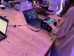
After adding some future improvements (the day after this was posted) I showcased the project in the I.M. showcase. In general, everything went fine, although I had to adjust quickly the mapping of the values of the photoresistor as well as increase a bit of the volume of the piezo buzzers; although this was done, it was still hard to hear them. Nevertheless, the flashlight mechanic was more than enough to keep players engaged. Here is some footage:

And some photos:
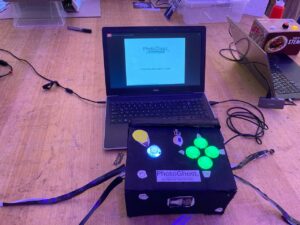
Figure 9. The set-up in the I.M. showcase
Figure 10. Playing.
Figure 11. Picture I took when I noticed someone was playing without my intervention.


Thanks for the class, I learned a lot!

Final Project Update and Progress – Marcos Hernández

Changes done to the project:

From the two suggested ideas, I decided to work on the first one since it would be the most realistic option. Now, the original first idea consisted in creating a platformer that would interact via the traditional directional moving buttons and a photoresistor, that would move the scenario according to how much light it received. Although, since I have already done a platform and time constraints, I had to modify this idea.

The idea still has the directional movement and photoresistor to interact with the game differently, but now there are significant changes such as:

  • It is now going to be from a top-down perspective, instead from a traditional 2-D.
  • It will feature enemies in the form of ghosts.
  • Time will serve as a metric for progression.
  • It now has a flashlight mechanic which serves to reveal the current position of enemies, but at the cost of an initial high consumption of battery and increased draining battery speed. This battery remaining for this mechanic will be display via LEDs that indicate, according to the scale of Green > Green > Yellow > Red. If the red LED light dims, the player will lose.
  • It has a “flashlight recharge station” which helps in increasing the current battery.
  • The enemies (Ghosts) can be detected, according to their current location and distance, via sound with the piezo speakers; in other words, if they are too near or far, the piezo speaker will make sounds according to it.
  • Random outcomes in every match due to the location of the player, enemies, and battery charges.
  • The photoresistor is now going to serve as to how fast the battery will charge. I am still going to allow external factors to interact with it to let the player have a certain degree of freedom. For example, the normal speed at which the battery charges in the stations are of 1x, but if a smartphone flashlight interacts with the photoresistor, it can increase up to 4x.

All of this has been implemented at the moment, but still need bug fixes, further improvements and user testing.

Current progress of the game:

You can move with the keys ESDF and you can use backspace to turn ON or OFF the lights. Keep in mind, because an Arduino is needed, the sound will not be played to locate the enemies, as also the external modification for the speed at which the battery is recharged.

Current Arduino Progress

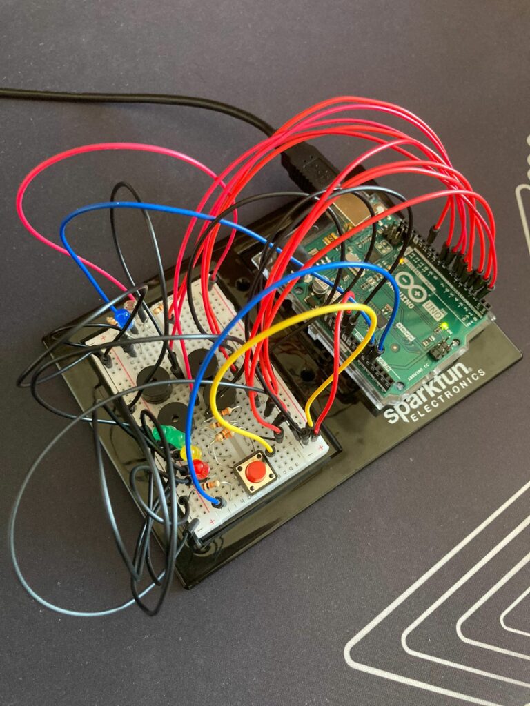
My current Arduino looks something like this at the moment:

I still need to implement the design and the buttons to move, but since I was mostly worried about the game mechanics and logic first, the design is something that I know will be straightforward to implement. Although, definitively, still time-consuming.


Reading Reflection – Week #12 by Marcos Hernández

The reading for this week made me think about the intersection between design, disability, and the self-perception of dignity. According to the reading, “the priority for disability has traditionally been to enable, while attracting as little attention as possible” (15). In other words, how can you make something that helps someone’s disability while aiding the person in not feeling uncomfortable due to being different? It is a difficult question, but as I was reading this, I had some thoughts.
It seems that our society values fashion in niches as well as being more open to try new things. For example, glasses went from being an only enabler to a wearable that is commonly found in fashion. Another example would be if we look into desktop mouses, they are devices who are there not to only assist a difficulty, but still make some tasks accessible. As for their design, they are not wearable per se, but were characterized by a simple and practical design, but nowadays, you will see mouses that range from office look to full on artistic; in other words, they are trying to find its niche market.
Regarding dignity, I do believe we should not feel ashamed of admitting that we are different. Those who have a financial incentive to profit from those in need should avoid further stigmatization by not making it super obvious that someone is different. As the book mentions, we have to avoid mediocrity. There are other observations that make me wonder in my mind as to what was an only-enabler, and now it’s a common wearable in our world, but that is an activity that requires careful observation and conscientization; there are a variety of problems that might be invisible to our current knowledge.

Week 12 Assignment – Exercises done in class by Marcos Hernández and Marwan AbdElhameed

Introduction

During class, we were asked to complete, in pairs, three exercises in order to get more familiar with the serial communication between Arduino and p5.js. The exercises asked the following:

EXERCISE 01: ARDUINO TO P5 COMMUNICATION

Make something that uses only one sensor on Arduino and makes the ellipse in p5 move on the horizontal axis, in the middle of the screen, and nothing on Arduino is controlled by p5.

EXERCISE 02: P5 TO ARDUINO COMMUNICATION

Make something that controls the LED brightness from p5.

EXERCISE 03: BI-DIRECTIONAL COMMUNICATION

Take the gravity wind example and make it so:

    • Every time the ball bounces, one LED lights up and then turns off
    • And you can control the wind from one analog sensor

Therefore, in order to complete the assignment effectively, we split it respectively, and we communicated along the execution, since we needed to make sure we were not only following instructions adequately, but that we could finish on time.

Exercise #1 and #2  –  Marcos Hernández

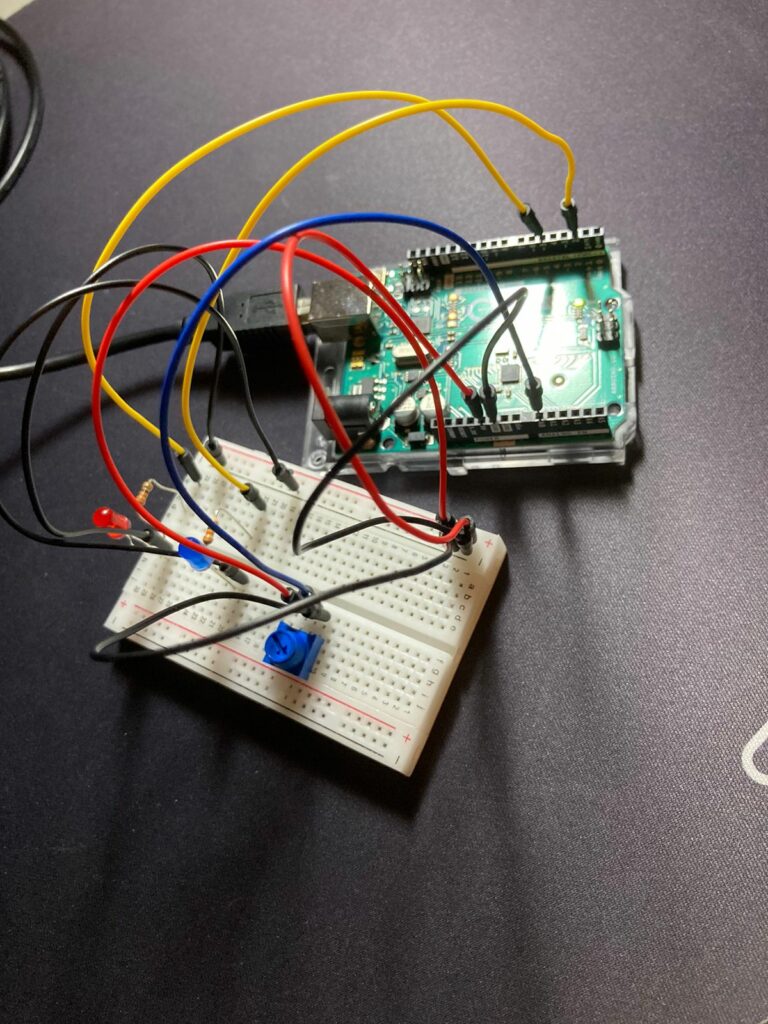
For this assignment, there was not any tweaking of the code done in the file provided (W11_01_Bidirectional_Com.ino) alongside the class presentation in Week 12.

So, for the set-up, I just prepared the Arduino in a way that it functions with the code without being modified, since it already did everything needed for these two exercises. Although, in p5.js, I duplicated the example that we were provided on class to work with. Likewise, I did make changes since it would not replicate what was needed for exercise #1 and #2.

After setting up the Arduino, we have the following:

And with this code in p5.js that is modified so as every time the circle is clicked, the red LED gets turn on as well as having the possibility of moving it horizontally with a potentiometer via analog values:

let rVal = 0;
let alpha = 255;
let left = 0; // True (1) if mouse is being clicked on left side of screen
let right = 0; // True (1) if mouse is being clicked on right side of screen

function setup() {
  createCanvas(640, 480);
  textSize(18);
}

function draw() {
  // one value from Arduino controls the background's red color
  background(255)

  // the other value controls the text's transparency value
  fill(255, 0,0)

  if (!serialActive) {
    text("Press Space Bar to select Serial Port", 20, 30);
  } else {
    text("Connected", 20, 30);
    // Print the current values
    text('rVal = ' + str(rVal), 20, 50);
    text('alpha = ' + str(alpha), 20, 70);
  }

  // click on one side of the screen, one LED will light up
  // click on the other side, the other LED will light up
  if (mouseIsPressed) {
    if (mouseX > rVal-50 && mouseX < rVal+50 && mouseY > height/2-50 && mouseY < height/2+50) {
      right = 1;
    } 
  } else {
    right = 0;
  }
  ellipse(rVal, height/2, 50,50)
}

function keyPressed() {
  if (key == " ") {
    // important to have in order to start the serial connection!!
    setUpSerial();
  }
}

// This function will be called by the web-serial library
// with each new *line* of data. The serial library reads
// the data until the newline and then gives it to us through
// this callback function
function readSerial(data) {
  ////////////////////////////////////
  //READ FROM ARDUINO HERE
  ////////////////////////////////////

  if (data != null) {
    // make sure there is actually a message
    // split the message
    let fromArduino = split(trim(data), ",");
    // if the right length, then proceed
    if (fromArduino.length == 2) {
      // only store values here
      // do everything with those values in the main draw loop
      
      // We take the string we get from Arduino and explicitly
      // convert it to a number by using int()
      // e.g. "103" becomes 103
      rVal = int(fromArduino[0]);
      alpha = int(fromArduino[1]);
    }

    //////////////////////////////////
    //SEND TO ARDUINO HERE (handshake)
    //////////////////////////////////
    let sendToArduino = left + "," + right + "\n";
    writeSerial(sendToArduino);
  }
}

We have the following result observed in the video:

After completing these exercises, I started to feel more confident as to how I will work on my final project.

Exercise #3  –  Marwan AbdElhameed

This one is particular was challenging. Basically, the sensor data is sent to Arduino after mapping it to -1,1, then the Y position of the ball is sent to the Arduino and checked if it was >330. If it is, the LED at is switched to HIGH.

The code found in p5.js:

let velocity;
let gravity;
let position;
let acceleration;
let wind;
let drag = 0.99;
let mass = 50;

function setup() {
  createCanvas(640, 360);
  noFill();
  position = createVector(width/2, 0);
  velocity = createVector(0,0);
  acceleration = createVector(0,0);
  gravity = createVector(0, 0.5*mass);
  wind = createVector(0,0);
}

function draw() {
    if (!serialActive) {
    text("Press s to select Serial Port", 20, 30);
  } else {
    text("Connected", 20, 30);
    // Print the current values
    text('rVal = ' + str(rVal), 20, 50);
    text('alpha = ' + str(alpha), 20, 70);
  }
  
  background(255);
  applyForce(wind);
  applyForce(gravity);
  velocity.add(acceleration);
  velocity.mult(drag);
  position.add(velocity);
  acceleration.mult(0);
  ellipse(position.x,position.y,mass,mass);
  if (position.y > height-mass/2) {
      velocity.y *= -0.9;  // A little dampening when hitting the bottom
      position.y = height-mass/2;
    }
}

function applyForce(force){
  // Newton's 2nd law: F = M * A
  // or A = F / M
  let f = p5.Vector.div(force, mass);
  acceleration.add(f);
}

function keyPressed(){
  if (keyCode==LEFT_ARROW){
    wind.x=-1;
  }
  if (keyCode==RIGHT_ARROW){
    wind.x=1;
  }
  if (key==' '){
    mass=random(15,80);
    position.y=-mass;
    velocity.mult(0);
  }
   if (key == 's') {
    // important to have in order to start the serial connection!!
    setUpSerial();
  }
}

function readSerial(data) {
  ////////////////////////////////////
  //READ FROM ARDUINO HERE
  ////////////////////////////////////

  if (data != null) {
    // make sure there is actually a message
    // split the message
    let fromArduino = split(trim(data), ",");
    // if the right length, then proceed
    if (fromArduino.length == 1) {
      
      wind = int(fromArduino[0]);
    }

    //////////////////////////////////
    //SEND TO ARDUINO HERE (handshake)
    //////////////////////////////////
    let sendToArduino = position.y + "\n";
    writeSerial(sendToArduino);
  }
}

The code sent to the Arduino:

int leftLedPin = 2;

void setup() {
  // Start serial communication so we can send data
  // over the USB connection to our p5js sketch
  Serial.begin(9600);

  // We'll use the builtin LED as a status output.
  // We can't use the serial monitor since the serial connection is
  // used to communicate to p5js and only one application on the computer
  // can use a serial port at once.
  pinMode(LED_BUILTIN, OUTPUT);

  // Outputs on these pins
  pinMode(leftLedPin, OUTPUT);

  // Blink them so we can check the wiring
  digitalWrite(leftLedPin, HIGH);
  delay(200);
  digitalWrite(leftLedPin, LOW);


  // start the handshake
  while (Serial.available() <= 0) {
    digitalWrite(LED_BUILTIN, HIGH); // on/blink while waiting for serial data
    Serial.println("0,0"); // send a starting message
    delay(300);            // wait 1/3 second
    digitalWrite(LED_BUILTIN, LOW);
    delay(50);
  }
}

void loop() {
  // wait for data from p5 before doing something
  while (Serial.available()) {
    digitalWrite(LED_BUILTIN, HIGH); // led on while receiving data

    int left = Serial.parseInt();
    if(left>=330){
       digitalWrite(leftLedPin, HIGH);
}
  
    if (Serial.read() == '\n') {
      digitalWrite(leftLedPin, left);
      int sensor = analogRead(A0);
      sensor = map(sensor,0,1023,-1,1);
      Serial.println(sensor);

    }
  }
  digitalWrite(leftLedPin, LOW);
}

After sending the setting up the Arduino, sending the code and using the one that was written in p5.js, we have the following result:

Conclusion

Working on Arduino, at first sight, might appear scary and too technical. But with these exercises, both my teammate and I feel more comfortable with the Arduino world. As they say, the hardest step will always be the first, and the rest, should be left to curiousness.


Final Project Ideas by Marcos Hernández

Introduction

For the final project, I am quite conflicted between the following two ideas: A platformer that uses light to move platforms or a Wario Ware like game which uses as much of the interactive mediums from Arduino as possible.

A platformer that uses light to move platforms

This project would be inspired by the simple mechanics of a platformer game like Super Mario Bros., but the difference is that, aside from only walking, the player possesses the power to interact with platforms through the use of light. This would be possible with the use of a photoresistor.

The game would consist of a set of three levels in P5, with the player only having three lives through the whole session. As for the controls, it would use a pair of two buttons to control the movement while a dedicated flashlight, that is close, is going to assist in moving the platforms. The platforms will have a set axis to move, and although simple and monotonous, obstacles such as flying bullets or damaging movable obstacles can also be included.

The Turbo $1 Flashlight | Arduino Project Hub

Figure #1 Image used for reference regarding the flashlight (Englishscone, 2018).

A Wario Ware like game using Arduino

Wario Ware is a video game developed by Nintendo that debuted in 2003. It presents a series of video games which include moving an umbrella to make sure a cat does not get wet to shaking the hand of a dog. All of this is done through the use of the characteristic touch screen capabilities of a Nintendo device. Therefore, the approach to this game using Arduino would be to randomize the set of minigames and prepare all the needed inputs in the Arduino devices.

For example, in P5, if a minigame requires that the player presses the button 10 times quickly, the player has to do so in the button that is near the Arduino. The other scenario as well is if the player needs to turn off the light in the minigame, which in this case would be done by covering the photoresistor.

The issue itself in this game would lie in how to convey rapidly what kind of input does the game want, as well as providing the Arduino input controls attractively.

Wario Ware Inc Mini Game Mania Review - Game Boy Reviews - Retro Garden

Figure #2 Some of the minigames presented in Wario Ware (Nintendo, 2003-Present day).

Conclusion

As always, all of these ideas will possibly change. Nevertheless, if this is given the time to properly experiment on the possibility of completing the selected project, then there is a guaranteed level of success only if ambitions are controlled and the video game is iterated multiple times.

Reading Reflection – Week #11 by Marcos Hernández

The readings provided for this week gives an interesting reflection on the current state of Interaction Design and what lies ahead. Contrary to the rant given by the author, I do believe (at least in a sense) that technologies that follows the design of “Picture under glass” can be both helpful and intuitive, but when used something else is lost: The human feedback.

In my daily life, the only touchscreen-based device that I use exclusively is my iPhone. The rest is through other physical mediums, such as keyboards and mouse. The key difference in them is that some can provide a greater level of feedback than the other, while still providing giving the same function. A book in a iPad is still going to display what I want to read, but the smell, the feel, the weight, and the feeling of possession are lost.

It is a bit sad how we are also seeing our society shift from a more human feedback to what it seems to be more robotic and productive. Take into consideration Microsoft’s “Productivity Future Vision”, a future where productivity reigns over the interactional design that fills the human being with the necessary non-visual feedback that tells the current state of the object. Regardless of this. Nevertheless, by raising awareness (as the author indicates) we can make sure that we still value projects that aim for the user to be more in touch with the inner-self; in control through the use of sensory cues other than the sense that one gets from touching a glass touch.

Week 11 | Mr. Problematico

Push the button, it screams. Turn the knob, and it screams even louder. For this week, we decided to create a sound/musical instrument that is controlled by a button and potentiometer.

Concept

We decided to call our machine, “Mr.Problematico” because of the issues we encountered while building this machine. The premise is simple: We have a potentiometer that controls the pitch and a button that plays/stops the music.

How it works

In the code, we mapped the potentiometer to 20 different notes. Then, we created an if-else statement, which plays a music function playMusic, whenever the button is pressed and does not play the music whenever it is not pressed.

In the music function, we played the note based on the value received by the potentiometer (value) and turned on the light as well.

 // Map the potentiomenter values according to the list length.
  int note = map(pontValue, 0, 1023, 1, 21);
  // If button is pressed, then play a sound according to the potentiometer.
  if (buttonState == HIGH) {
    playMusic(note);
    //Serial.print("HIGH \n");
  }
  else if (buttonState == LOW) {
    //Serial.print("LOW \n");
  }
}
//Play the tune, wait a specific time and light the LED according to the 
//arrays of melodies and duration. In other words, the LED and the sounds generated are synchronized. 
void playMusic(int value) {
  int noteDuration = 1000 / noteDurations[value];
  digitalWrite(13, HIGH);
  tone(8, melody[value], noteDuration);
  digitalWrite(13, LOW);
  delay(noteDuration);
}
Closing Remarks

During our building time, we spent a lot of hours trying to figure out why our machine decided to stop very long when we executed the music function. After some consultation, the delay function delays the whole machine rather than the code line. We tried to play and go around trying to fix this weird delay. We figured out that by missing a resistor to the button that messed up the whole circuit, before eventually creating the machine above. It was not completely the code’s fault but rather our miss information.

We’re quite proud of this project. Looking forward to the final project!

Reading Reflection – Week #10 by Marcos Hernández

In this post, you will find each individual reading reflection assigned for week 10. These reflections will be mostly based on my experiences, so actual discussion on the contents of the writing will be somewhat limited since I feel that it would be redundant to summarize what is there.

Making Interactive Art: Set the Stage, Then Shut Up and Listen

Generally, I associate the term Interactive Art with video games. According to the article, we are not supposed to readily give interpretation of our own works due to possibly adding bias and making boring the interactive experience for others. For example, in mysterious abstract video games, I have seen authors avoid giving full explanations to seemingly inconclusive questions in order to keep conversations, theories, and engagement alive. In a confusing title such as OFF (Mortis Ghost, 2008) the world that it presented is full of mysterious elements. At first sight is difficult to give an explanation to, nevertheless it invites the player to give its own reasoning to this interactive art.

As for other interactive art mediums, I often found myself walking on the corridors of the Arts Center building to see some interesting digital arts, such as a screen that portrays me in symbols. There are many other examples, but what they have in common is that they apply the concept of “show, don’t tell” that I really love about video games, since it leaves the spectator/player alone with the interactive art. In other words, it is a personalized experience: I will find an interactive digitalized portrait of myself super thought-provoking, while a friend could just find it funny. Different experiences, but there is not a fixated idea due to not having the author directly explain it to us as to why the existence of the created interactive art.

Physical Computing’s Greatest Hits (and misses)

During my time as a child, I have seen a correlation between success and devices that challenge pre-established formulas. For example, in today’s world (today as at the time I am writing this) computer mouses are generally used due to facilitating the computer experience, it facilitated it so much that the entire computer GUI landscape adapted to it. It acts as a “third hand” that gets materialized into the digital world, where if you want to “grab a file”, you just have to hold the mouse with one of your fingers in order to simulate the action of grabbing. It was a great hit, but what about other technologies that try to revolutionize or seek general fun?

I would like to imagine a James Bond like hand watch as a replacement for the watches we have now, such as the Apple Watch. One finds (small) pleasure in using the watch to quickly watch the time and timely arrange the next activities to do, as well as it also looks and feels nice to have due to the possible elegance it possesses. But what about making it a very curious device, such as the one that James Bond has? Imagine this: you have a clock that looks impressive, thus it is pleasurable to wear, but also has a laser, camera, and magnetism included on it. Yes, one can easily argue that this idea is already done to death in many series and movies as an inspiration, but still, one can find other workarounds to this theoretical watch; a remix act. So, instead of creating an actual James Bond like that shoots lasers, what about throwing confetti in miniature? One could find pleasure in annoying friends and family with the functionality.

In conclusion, I found this article curious as I noticed some patterns in successful products, such as the indirectly mentioned Dance Dance Revolution Dance Pads in the writing. The world of physically interactive art has its market, because it is pleasurable and fun to experiment with items one might never be seen before.

Assignment #6 – Switchable Lights by Marcos Hernández

Introduction

For this week, I tried to imagine something complex to do, but due to creative bankruptcy, I could not imagine any interesting mechanisms for this Arduino. Although, I still wanted to experiment with what we have learned in class so far.

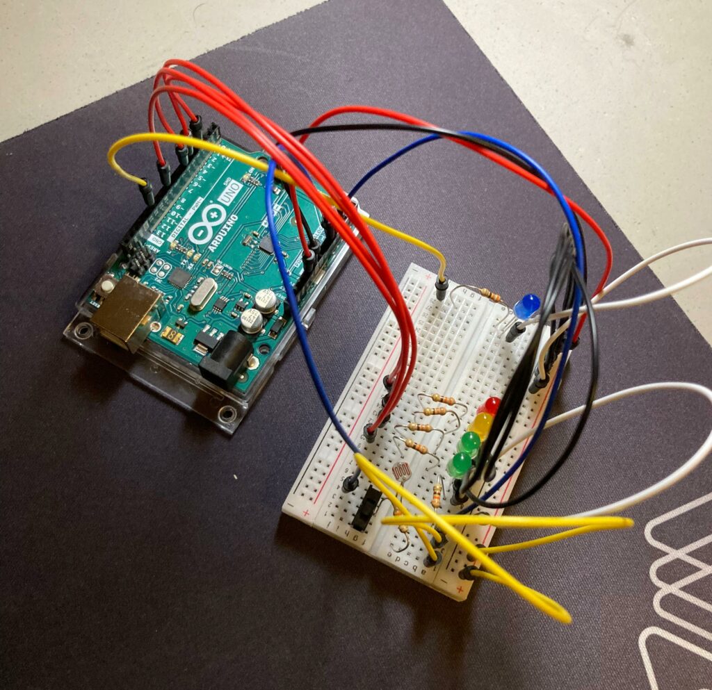
When we were experimenting with the photoresistor, I was curious to see what kind of patterns I could make with the use of the device, LEDs, and the mapping function. Thus, I came with the idea of doing a volume meter inspired light detector.

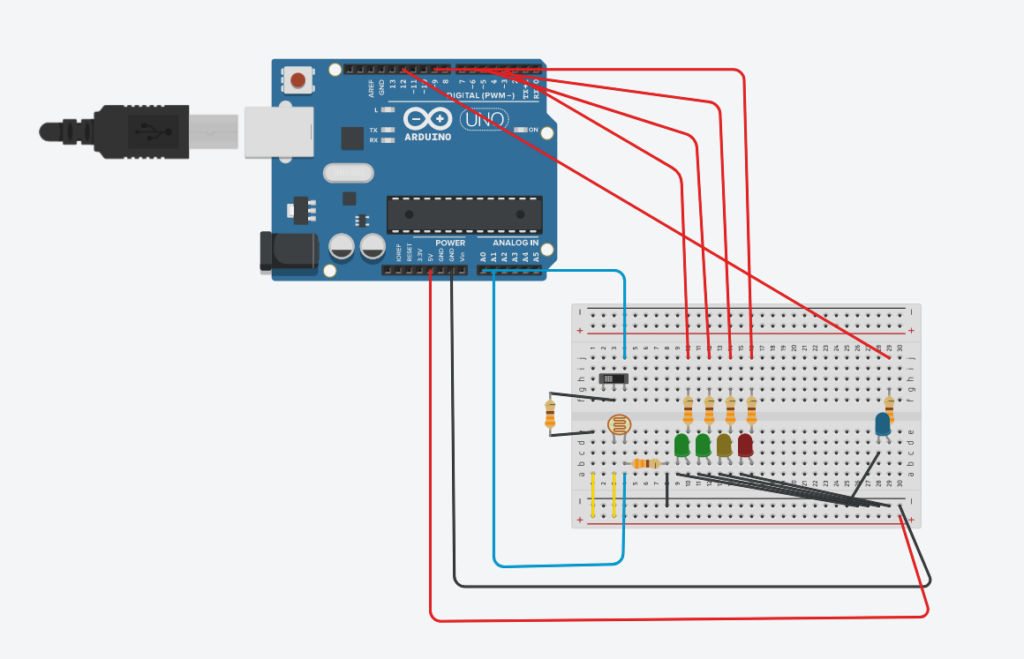
Figure #1: Arduino made in person.

Materials

    • 7 330-ohm resistors.
    • 2 green LED lights.
    • 1 yellow LED light.
    • 1 red LED light.
    • 1 blue LED light.
    • A breadboard.
    • 8 red jumper wires (due to being low in red jumper wires, three are yellow).
    • 7 black jumper wires (again, due to being low, 2 are white).
    • 2 blue jumper wires.
    • An Arduino board with, 5V, GND, analog and digital output and input.
    • A slideswitch.

Implementation & Usage

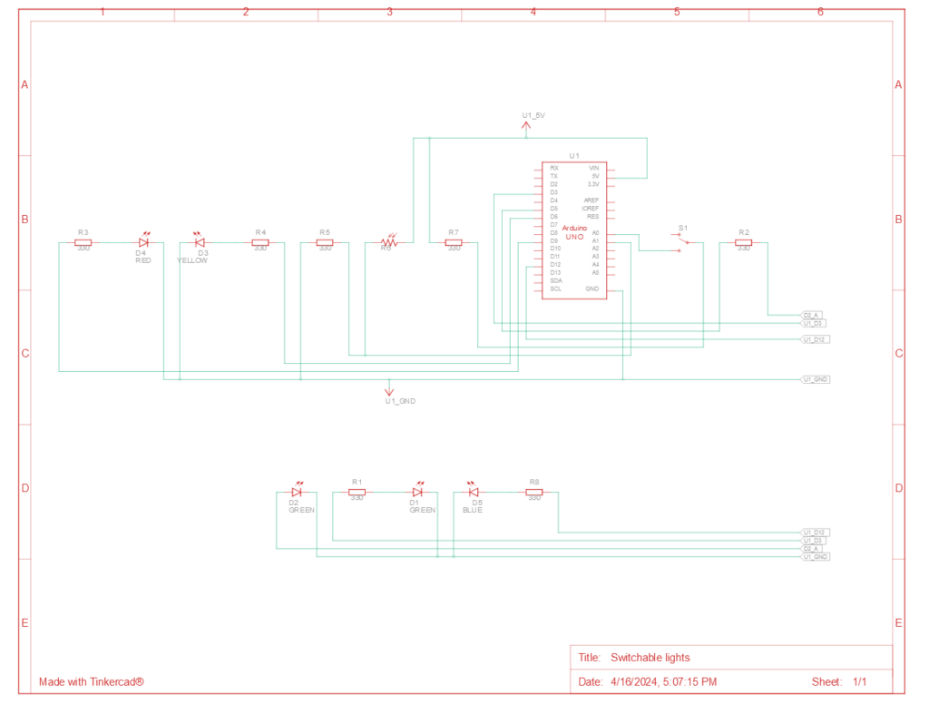
Once all the materials are set up like in the schematic and the Arduino is powered, the user can do either of the following according if the slideswitch is ON or OFF:

1. If the slideswitch is ON, a blue LED will indicate this state. In this mode, if a light source is redirected to the photoresistor, the LEDs will turn on, like a volume meter, depending on the strength of the source.

2. If the slideswitch is OFF, the blue LED light will be off, indicating this state. In this mode, a non-interactable sequence where each LED light will be displayed, where they will be turning ON and OFF in a 0.5 second basis.

Both modes can be interrupted at any time.

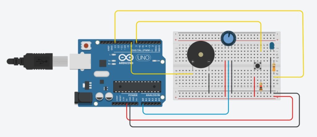
Schematics

Figure #2: Schematic #1 made in Tinkercad.

Figure #3: Schematic #2 made in Tinkercad.

Code

For the coding, I used the blocks GUI from Tinkercad, and then transform it into code to change it according to my necessities, as well as add some comments to it to further explain some functionalities.

//We will only use two variables for this Arduino set up:
//Brightness is to receive the analog values from the photoresistor, to use to turn ON the LEDs.
//Switchstate will alternate between states depending on the analog valaue received.

int brightness = 0;
int switchstate = 0;

void setup()
{

  // Preparing the Arduino and variables initialization.
  pinMode(A0, INPUT);
  pinMode(A1, INPUT);
  Serial.begin(9600);
  pinMode(3, OUTPUT);
  pinMode(5, OUTPUT);
  pinMode(6, OUTPUT);
  pinMode(9, OUTPUT);
  pinMode(12, OUTPUT);

  brightness = 0;
  switchstate = 0;
}

void loop()
{
  switchstate = analogRead(A0);

  // According to the amount of light received by the photoresistor, it will turn on the LEDs. For example,
  //if the light source is too strong, all LEDs will turn on, if it is too low, either 1 or 2 will be ON.

  if (switchstate > 1013) {
    digitalWrite(12, HIGH); // Blue LED indicates light mode.
    brightness = analogRead(A1); //Receive values from the photoresistor.
    Serial.println(brightness); //and print it to serial.
    if (brightness > 100) {
      analogWrite(3, map(brightness, 0, 1023, 0, 300)); //First green LED will be turn on and its intensity will depend on the intensity of the light source. Also, we map the values received since if it is too high, then it will basically loop; mapping makes sure that it always states in a range.
      if (brightness > 200) {
        analogWrite(5, map(brightness, 0, 1023, 0, 300)); //Second green LED will be turn on and its intensity will depend on the intensity of the light source. The rest is the same.
        if (brightness > 300) {
          analogWrite(6, map(brightness, 0, 1023, 0, 300));
          if (brightness > 400) {
            analogWrite(9, map(brightness, 0, 1023, 0, 300));
          } else {
            digitalWrite(9, LOW);
          }
        } else {
          digitalWrite(6, LOW);
        }
      } else {
        digitalWrite(5, LOW);
      }
    } else {
      digitalWrite(3, LOW); //If it fails to meet the requirement, the it will turn OFF without exceptions. It is the same for the rest of LEDs.
    }


  } else {
    // Each LED gets turn on and off in order.
    digitalWrite(12, LOW); // Blue LED gets shut down.
    digitalWrite(3, HIGH);
    delay(500); // Wait for 500 millisecond(s)
    digitalWrite(3, LOW);
    digitalWrite(5, HIGH);
    delay(500); 
    digitalWrite(5, LOW);
    digitalWrite(6, HIGH);
    delay(500); 
    digitalWrite(6, LOW);
    digitalWrite(9, HIGH);
    delay(500); 
    digitalWrite(9, LOW);
    Serial.println(switchstate);
  }
}

Showcase

In this video, I show how the Arduino looks and operates. Please keep in mind that the color of some jumper wires had to be mixed up (at least strategically) due to material constrains, in order to still convey the positive and negative connections.

Challenges

The biggest challenge in this Arduino was, actually, making the photoresistor to work. The reason of this difficulty was that I had forgotten how to set up the photoresistor properly, even though we were taught how to do so in class. Although, with a YouTube video and quick review of the slides, I was able to pick up again what I needed to do and not question myself why I was getting a consistent analog value of 1024 from my photoresistor.

Reflection

I am feeling that I am going a bit bankrupt creatively. I do admit that this Arduino took me time to develop, but the many ideas I had in my mind are still not able to come into fruition. Likewise, I personally feel that this is like the previous scenario in the first half of this semester, where I was mostly experimenting with the provided tools in order to have a greater idea of what is possible to do. It is likely it will happen in this case, but still, I wish I could come with more ideas to develop more curious devices.

Nevertheless, I did learn something new from this Arduino, like how to effectively map some values and how to set up properly a device (ignoring the selection of colors of the jumper-wires of course) to capture values from two points: the photoresistor and the slideswitch.


Thanks for reading this and have a happy day.


Assignment #5 – Unusual Switch (Unconventional mask) by Marcos Hernández

Introduction

For this week assignment, I have been thinking in how to properly implement it. I was thinking in using water, but none of the ideas that came into my mind were fun for me. I also think of using my eyes, but it was too uncomfortable, then I thought about the materials I had in my dorm, and I got reminded of the mask I have.

Not only that, but I have to admit that I generally do not come up with a plan, almost everything I do is spontaneous in a way. Therefore, following this methodology, I grabbed my mask and started in thinking in ways I can accomplish this task.

Materials

    • A 330-ohm resistor.
    • 1 LED light (in this case is red).
    • A breadboard.
    • One red and two black jumper wires.
    • An Arduino board with a 5V and GND output.
    • A mask.
    • Cooper.
    • Tape.
    • Glue.
    • Something to hold the mask in a place.

Process

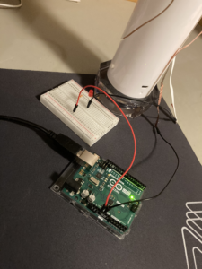
I needed to set up my Arduino first since, obviously, there would not be any result if it was not properly set up. Therefore, I created the basic connection that consisted in outputting 5V and GND with the use of the jumper wires, although only the red jumper wire was connected. The two black jumper wires were partially connected in order to create the bridge with the use of a conductive material; in this case, cooper.

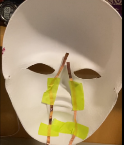
The mask needs to be prepared in the following way, with the use of cooper and tape:

Also, make sure that the cooper not only is held with tape on the mask, but that the cooper is long enough to paste the male connections of the jumper wires.

Once everything was connected to the breadboard. A resistor was placed in order to receive the positive connection to send to the red LED, and the male connections of the black jumper wires were glued into the loose cooper:

As for the way to create the bridge, there are several ways in which you can approach this. The idea here is to put on the mask without relying on the hands, and for this, I first I made sure that the mask was sitting in one place with the help of a base (in my case, my lamp). Following this, I taped my nose with some cooper in order that, once I put my face into the mask, the taped cooper on my nose would create the bridge and light up the red LED.

Showcase

Observe the following video to see how it operates:

Reflection

I am new to the world of Arduino, and while this is not the most elaborate work, I had fun making it. Yes, not using my hands limited my possibilities, but this comes at the benefit of actually trying to be even more creative. I am curious to see what are the next projects in the course, since I have seen some videos involving this device, although most of them were at the software level; the hardware level is a bit unknown for me.