Week 13 – Final Project

Båige – Horse Race!

User testing is in a separate blog post. Here is the video of my final project-> FINAL PROJECT VIDEO

My Concept: The project is an interactive game about the horse race, one of the traditional games in Kazakh culture. As horse riding was a part of our nomadic lifestyle, we have a lot of games connected with horse riding. One of these games is called Båige as the name of this game, where the equestrians compete with each other while riding the horses and that might include overcoming some obstacles. I wanted to incorporate that into my game: the user is an equestrian, riding the horse and avoiding obstacles in the form of snakes while collecting the stars that add up extra points to the score. As the game progresses, the snakes move faster, making the game harder for the user. 

The implementation of the idea: To implement the idea four main buttons were used, which are responsible for each of the lines in the racing game. When the button is pressed, the horse moves to the corresponding line. To make the experience of racing, the obstacles and the awards are added to the game, so the user should avoid the former and collect the latter, adding up to the score. 

Description of interaction design: The user interacts with the game by pressing the physical buttons on the box, each of which is responsible for the corresponding line as shown in Fig 1. For instance, when the user presses the red button on Arduino, the equestrian on the p5.js moves to the red line. Hence, when the obstacles appear in the way of the user, the user will try to press the buttons of the lines with no obstacles. More obstacles are avoided, and more score is given to the user. Furthermore, the stars appear on the p5.js and by pressing the buttons of the lines with the stars, the user will be able to collect these stars and add extra points to the score. When the user collides with the snakes, the game is over and the score collected by the user shows up. 


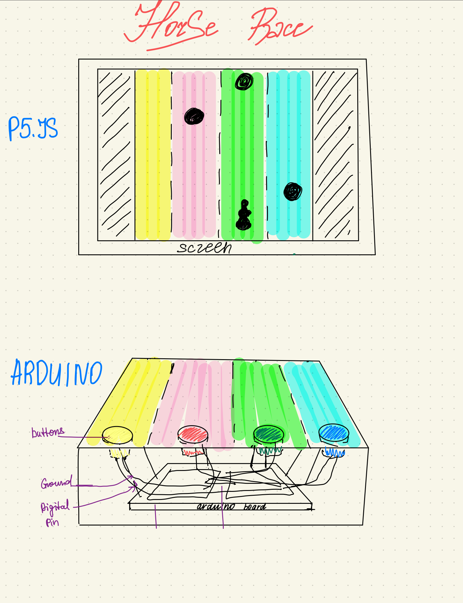
Fig. 1. P5.js and Arduino set up sketch

Description of Arduino code: The Arduino code declares the buttons as digital inputs with internal pull-up resistors. It checks if the buttons are pressed and sends the corresponding number through serial if they are pressed. For instance, if the white button is pressed, the number 1 is sent to the serial communication. The delay was added, so when the button is pressed once, only one number is printed and sent. 

Link to full Arduino sketch:

// Intro To IM - Fall 2023
// Michael Ang
// Final Project - Baige- Horse Race! 
// Diana Alibekova

// assigning pins to the buttons and declaring them as constant int, so their values will not be accidentally altered
const int greenbutton = 2;
const int yellowbutton = 3;
const int redbutton = 4;
const int whitebutton = 5;
const int startbutton = 6;

void setup() {
  //activating the serial communication
  Serial.begin(9600);
  //declaring the buttons as digital inputs with internal pull up resistors (the external resistors are not used)
  pinMode(greenbutton, INPUT_PULLUP);
  pinMode(yellowbutton, INPUT_PULLUP);
  pinMode(redbutton, INPUT_PULLUP);
  pinMode(whitebutton, INPUT_PULLUP);
  pinMode(startbutton, INPUT_PULLUP);
}

void loop() {
  // checking if the buttons are pressed and sending the corresponding number through serial if they are pressed
  if (digitalRead(whitebutton) == LOW) {
    Serial.println(1);
    // delay is needed because it pauses the program for a half a second, so only one press of the button is registered.
    delay(500); 
  } else if (digitalRead(redbutton) == LOW) {
    Serial.println(2);
    delay(500);
  } else if (digitalRead(yellowbutton) == LOW) {
    Serial.println(3);
    delay(500);
  }
  else if (digitalRead(greenbutton) == LOW) {
    Serial.println(4);
    delay(500);
  }
  else if (digitalRead(startbutton) == LOW) {
    Serial.println(0);
    delay(500);
  }
}

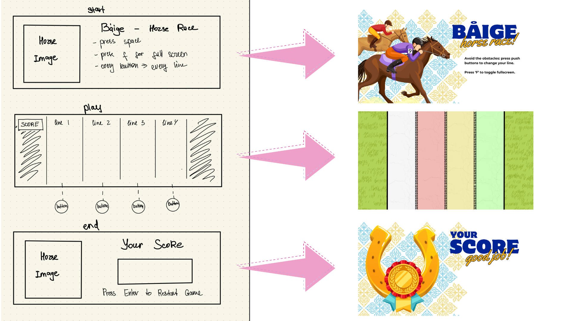
Description of p5.js code: The images and sounds are preloaded before the setup runs. The game has three states: start with instructions given, play with the game playing, and end with the score obtained as shown in Fig. 2. In the instructions, the image with the instructions is shown and the serial communication is set by pressing the space key button and choosing the serial port. By pressing the start button on Arduino, the number ‘0’ is sent to the p5.js, which is interpreted as the transition between the states. So, the game transitions to the game-playing state. In this state, the background image of the racing lines is displayed with the moving obstacles, bonus stars as well and the horse of the user. In the beginning, the horse is in the initial position given unless the number is sent to the p5.js by pressing one of the four buttons on Arduino. When the button is pressed, the number is sent to p5.js and the horse moves by x coordinate accordingly. Moreover, there are the moving obstacles, which appear randomly in the x coordinates of windowWidth * (3 / 12), windowWidth * (5 / 12), windowWidth * (7 / 12), windowWidth * (9 / 12) and move by y coordinate and increase the speed. Initially, these obstacles were identified as the circles as well as the horse, so the minimum distance between them was calculated as the obstacle.radius + (circleRadius / 2). The collision was identified when the distance between the obstacle radius and the circle (horse) radius was smaller than the minimum distance. When they collide, the game ends by freezing the image or sleeping for a second and then transiting to the end state. A similar approach was taken with the bonus stars, but the collision with them added extra points to the score. The score was calculated by every obstacle passing through the window, so the y coordinate of the obstacle circle is greater than the window height. In the end state, the end image is displayed with the score.

Fig. 2. Game states

The code I am proud with:  I am particularly proud with the code of calculating the distance between the obstacles and the circle (horse) to determine the collision.

// for loop accessing each obstacle in the array and calcilating the distance between the horse and obstacle as well as minimum distance for collision to occur
 for (let i = 0; i < obstacles.length; i++) {
  let obstacle = obstacles[i];
  let distance = dist(circleX, windowHeight * (2 / 3), obstacle.x, obstacle.y);
    let minDistance = obstacle.radius + (circleRadius / 2);

// if the horse collides with the obstacles, then the game is over, transitting to end game state and playing the winning sound
  if (distance < minDistance) {
    wonGame = false;
    // transitting to end game state
    gameState = 'end';
    level_win.play();
// if the horse doesn't collide with the obstacles, for each of the obstacles passed through the window height, the score is incremented. 
  } else if (obstacle.y > windowHeight && !obstacle.passed) {
      obstacle.passed = true; 
      score++; 
    }
}

Embedded p5.js code: 

Description of communication between Arduino and p5.js: there are five buttons on Arduino. Every time the button is pressed, the corresponding number is written down, which is sent to p5.js. For every one of these numbers, there are the x coordinates of the horse. Hence, the horse moves by x coordinate depending on the number taken. For instance, when the red button is pressed, the number 4 is sent to p5.js, meaning that the horse should move to the windowWidth*(3/12). 

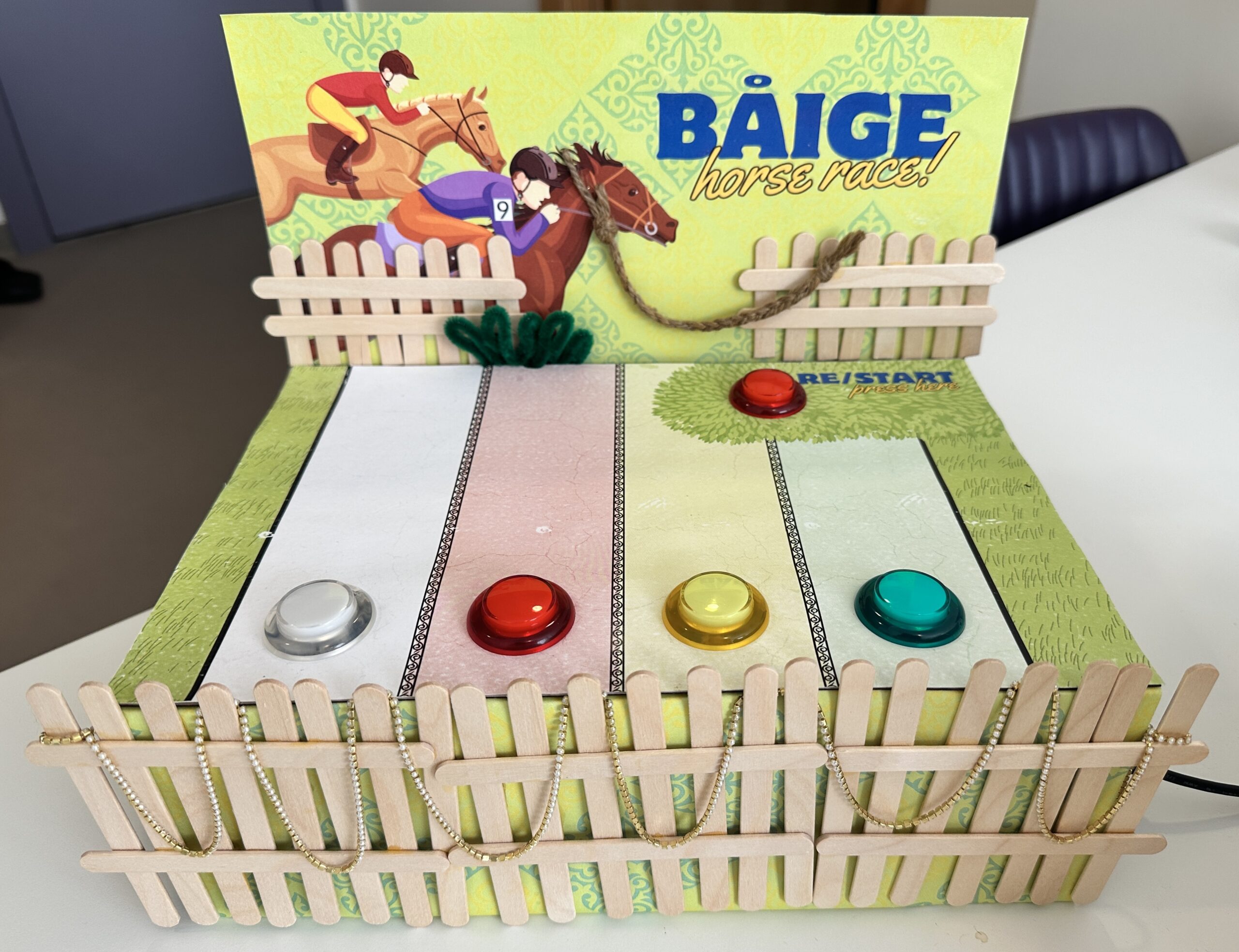
The aspects of the project I am proud of: Overall, I am very proud of the final product because I see the development of creative coding skills from absolute zero to something that can be presented in the IM Show. Specifically, I am proud of being able to correctly create the serial communication between Arduino and p5.js, so the Arduino sends the number every time the button is pressed and that number is rightly interpreted by p5.js and moves the horse by x coordinate. Moreover, as this is my very first dynamic game project, I am proud of being able to code the moving obstacles and awards as well as the collision between them. When the horse collides with an obstacle, the game is over, while when it collides with the award, bonus points are given to the score. Last but not least, I am very proud of the physical decoration I made shown in Fig. 3. because overall the project looks aesthetically pleasing and engaging. 

Fig. 3. Decor

The areas of improvement: There are some improvements to the project that I would like to add in the future. For instance, it would be great if the score of the users could be saved and created the list of users with the highest score in the game. This would create a sense of competition with others, making the game more interesting. Furthermore, there are minor details that would enhance the experience of playing the game such as whenever the collision with the snake happens, the image of the horse and snake changes as if the snake was biting the horse or something similar. I had that idea but I couldn’t find the image which would satisfy that. Hence, I think in the future, I might draw the images of the snake and horse and import them. Additionally, the moving trees and houses on the sides would be a great addition, enhancing the experience that the horse is moving. Moreover, as an improvement for the game, it would be great if two or more people could play the game together and compete with each other. In this case, the game would look like a horse race. 

Resources used

Week 13 – Final Project – User Testing

Båige: Horse Race!

I conducted user testing twice with different people before improving the project and after improving it. Both of the times, I gave the users the game without explaining it, but they had a chance to read the short instructions on the game itself. 

Before improving the project: The game didn’t have the physical decoration as the box with the lines, but the small push buttons on the Arduino. Overall, the game experience was good and the people asked to play again and again. Yet, there were several issues. First, because of the absence of the physical implementation of the lines with the decoration, it was hard for the users to immediately understand what each of the buttons does and is responsible for. As it is shown in video 1, small buttons have nothing except the colors, giving a hint that they are responsible for the position of each of the lines. Because of this, they had to play around with buttons and figure it out by themselves. As soon as they figured it out, it was much easier and more interesting to play. Second, sometimes when the users clash with the obstacles, it happens so fast that the users might not understand where it happened. Hence, it seems like the game finished out of nowhere.  Third, in terms of user experience, it was a bit inconvenient for the users to always press the button “Enter” to start and restart the game. 

First video: before improving

After improving the project: All three points mentioned above were improved and implemented. First, the physical box with four colored lines with buttons of the same color on top of them and the decorations were added. Because of this, the users were able to figure out the functionality of the push buttons quickly. Second, the sleep function was added, so when the user clashes with the obstacle, the picture freezes for a second, showing the clash. In this case, no matter how fast was the clash, the user will be able to see that. Third, I added one more button responsible for starting and restarting the game, so the user doesn’t have to touch something outside of the buttons. After improving these things, the overall experience of playing the game was much better. Yet, there were times when the user didn’t hit the snake, but the game was over. This happened because the distance of collision was a bit more than the image, so I had to decrease that.

Second video: after improving

Week 11 – Reading Response

I find it interesting how smooth was the transition of the perspective on the eyeglasses from the ‘sign of disability’ to a fashionable item. This idea became so popular because of the unique design and style of the eyeglasses that they are bought by people with no issue with eyesight just because they are fashionable, adding to the style and creating an overall image. Hence, eyeglasses became something that we don’t hide but rather emphasize in a stylish way, changing our view on disability as something we have to hide or be ashamed of. 

While reading the article, I started questioning whether the same approach can be applied to bigger items such as wheelchairs. Although for now there is not much to do for the design of the wheelchairs, their functionality is advancing day by day. However, it is not an absolute solution as not all the facilities in the urban and rural areas are made for wheelchairs. I feel like they consider themselves as people with disabilities mostly when there is a hardship in the movement in the city as not everything is made accessible. Therefore, I believe that not only the design of the items for accessibility should be improved, but also the things all around should be designed to be accessible. 

Although the transition for other items is not as fast as with the eyeglasses, I appreciate the work of designers in trying to make other disability items through the changes in the design of the items, raising awareness about their normality in the magazines, etc.

Week 11 – Series Connection

Exercise 1: make something that uses only one sensor on arduino and makes the ellipse in p5 move on the horizontal axis, in the middle of the screen, and nothing on arduino is controlled by p5

Using the ultrasound sensor, the circle moves horizontally on the canvas.

Video: exercise_1_week_11


Arduino code:

#define echoPin 2
#define trigPin 3


long duration;
int distance;


void setup() {
pinMode(trigPin, OUTPUT);
pinMode(echoPin, INPUT);
Serial.begin(9600);


}


void loop() {
digitalWrite(trigPin, HIGH);
delayMicroseconds(10);
digitalWrite(trigPin, LOW);
duration = pulseIn(echoPin, HIGH);


// Calculate distance in centimeters
distance = duration * 0.034 / 2;


Serial.println(distance); // Print distance in centimeters
delay(100); // Delay for stability
}

Exercise 2: make something that controls the LED brightness from p5. 

The LED brightness is controlled by the vertical distance of MouseY and the top of the screen. The higher the distance the brighter the LED. So, when the user drags the ellipse from the top to the bottom of the canvas, the brightness of the LED increases proportionally and vice versa.

Video: exercise_2_week_11

Arduino code:

//exercise 2, week 11, controlling the brightness of LED with p5.js
//Diana and Buka
// Output:
// - 5 - LED

const int ledPin = 5; //the LED pin is at 5

void setup() {
 // Start serial communication so we can send data
 // over the USB connection to our p5js sketch
 Serial.begin(9600);
 // use the builtin LED as a status output.
 pinMode(LED_BUILTIN, OUTPUT);
 pinMode(ledPin, OUTPUT);

 // Start the handshake
 while (Serial.available() <= 0) {
   digitalWrite(LED_BUILTIN, HIGH); // on/blink while waiting for serial data
   Serial.println("0"); // send a starting message
   delay(300); // wait 1/3 second
   digitalWrite(LED_BUILTIN, LOW);
   delay(50);
 }
}

void loop() {
 // Wait for data from p5 before doing something
 while (Serial.available()) {
   digitalWrite(LED_BUILTIN, HIGH); // LED on while receiving data
   // reading the integer value, confirming that the next character is a new line and sending confirmation 1
   int brightness = Serial.parseInt();
   if (Serial.read() == '\n') {
     delay(5);
     Serial.println("1");
   }

   // LED brightness is set accordingly
   analogWrite(ledPin, brightness);
 }
 digitalWrite(LED_BUILTIN, LOW);
}

Exercise 3: take the gravity wind example and make it so every time the ball bounces one led lights up and then turns off, and you can control the wind from one analog sensor

The LED is on when the ball is on the ground / hits the ground when bouncing. And the ball can be controlled by the potentiometer to move left and right.

Video: exercise_3_week_11.mov

Arduino code:

const int LED_PIN = 3;
const int SENSOR_PIN = A2;


void setup() {
Serial.begin(9600);
pinMode(LED_PIN, OUTPUT);


// Test the LED
digitalWrite(LED_PIN, HIGH);
delay(500);
digitalWrite(LED_PIN, LOW);
}


void loop() {
int p_value = analogRead(SENSOR_PIN); // read from the potentiometer
int move = map(p_value, 0, 1023, -1, 2); // map the value to -1, 0, and 1
Serial.println(move);


if (Serial.available() > 0) {
// read from p5.js
int touch = Serial.parseInt();
// set the LED command
if (touch == 1) {
digitalWrite(LED_PIN, HIGH);
} else {
digitalWrite(LED_PIN, LOW);
}
}
}


Week 11 – Final Project Proposal

Horse Race

Concept: Historically, Kazakhs are nomadic people, migrating from one place to another every season of the year. Because of this, we have many national games and traditions connected with horse riding. I would like to connect my final project with one of the Kazakh national games called Båige, which means competition in horse riding. The people compete with each other in horse riding, so the winner is the person who comes first to the finish line. Throughout the game, there might be several barriers the equestrians should successfully overcome. In my game, I would like to make four lines with the appearing barriers. The user is going to be the equestrian on the horse, who should overcome the obstacles, which will speed up by the time. In addition to that, I would like to add the Kazakh national music as the background sound playing throughout the game. 

The technical implementation: On the p5.js screen, there are going to be four lines with the appearing obstacles and the image of the equestrian. In front of the user, there are going to be four squares, each representing the line of the game. I will stick the aluminum to the base of the figure of the equestrian, so that when the user taps the equestrian on the square, the aluminum connects the wires, completing the circuit. In other words, when the equestrian figure taps the first square, the first circuit is completed, indicating to the p5.js that the equestrian is on the first line. 

Week 10 – Musical instrument

Concept: We created a basic radio that switched between two channels, each playing different songs, by adjusting a potentiometer. Inspired by the upcoming festive season, even though it is too early, we decided to integrate the beloved tune “Jingle Bells” into our project.

Video Demonstration: musical instrument

Implementation:

We used a switch, a potentiometer, and a buzzer in our setup. The switch turns on and off the radio, and the potentiometer switches between channels. Initially, we planned to include two songs: “Jingle Bells” and “Let It Be.” However, converting “Jingle Bells” into playable chords was a bit of a challenge. Consequently, the potentiometer plays “Jingle Bells” when set in the first half and stays silent in the second half.

To achieve the authentic “Jingle Bells” melody, we discovered the chords and their timing online. These chords, when played together, compose a recognizable tune. We organized this chord information into an array named “melody” in our code. Each chord in this array was linked to a specific frequency, dictating the notes played. Assigning these frequencies to each chord enabled us to establish a precise sequence of notes within the melody array, ultimately generating the iconic “Jingle Bells” tune. Later in the loop, it iterates through the melody array. Within the loop, it retrieves each note’s frequency and plays it for a specified duration using the buzzer.

const int POTENTIOMETER_PIN = A0;
const int BUZZER_PIN = 3;
const int threshold = 512;

// Define each chord's frequency
#define C 261
#define D 294
#define E 329
#define F 349
#define G 392
#define A 440
#define B 493
#define REST 0

void setup() {
  pinMode(BUZZER_PIN, OUTPUT);
  Serial.begin(9600);
}

void loop() {
  int analogValue = analogRead(POTENTIOMETER_PIN);
  Serial.println(analogValue);

  if (analogValue > threshold) {
    playJingleBells();
  } else {
    noTone(BUZZER_PIN);
    delay(100); // Delay to reduce loop frequency
  }
}

void playJingleBells() {
  // Melody and Timing
  int melody[] = {
    E, E, E, REST,
    E, E, E, REST, E, G, C, D, E, REST,
    F, F, F, F, F, E, E, E, E, D, D, E, D, REST, G, REST,
    E, E, E, REST,
    E, E, E, REST, E, G, C, D, E, REST,
    F, F, F, F, F, E, E, E, G, G, F, D, C, REST
  };
  int noteDurations[] = {
    4, 4, 4, 4,
    4, 4, 4, 4, 4, 4, 4, 4, 4, 4,
    4, 4, 4, 4, 4, 4, 4, 4, 4, 4, 4, 4, 4, 4, 4, 4,
    4, 4, 4, 4,
    4, 4, 4, 4, 4, 4, 4, 4, 4, 4,
    4, 4, 4, 4, 4, 4, 4
  };

  int melodySize = sizeof(melody) / sizeof(melody[0]);

  for (int i = 0; i < melodySize; ++i) {
    int noteDuration = 1000 / noteDurations[i];

    if (melody[i] != REST) {
      tone(BUZZER_PIN, melody[i], noteDuration);
      delay(noteDuration); // Let the note play for its duration
    } else {
      delay(noteDuration); // If it's a rest, delay without tone
    }
    
    noTone(BUZZER_PIN); // Stop the note
    delay(50); // Delay between notes for spacing
  }
}

Reflection & Future Improvements: As it was mentioned before, we wanted to create a radio with two channels, playing two different songs such as “Jingle Bells” and “Let It Be”, depending on the resistance of the potentiometer: the first half plays one song, and the second half another. However, we spent a lot of time working on our beloved Christmas song, finding the right chords, and frequencies, and figuring out the logic of making it play, so we didn’t have much time left to work on the second song. Because of this, we decided to make another channel of our radio empty for now, so we could add the song in the future. In addition to that, we would like to work on the aesthetics in the future by creating the painted cardboard in the form of the radio to create a more realistic experience.

Week 10 – Reading Reflection

When I started reading the text “Hands”, I felt like the author was telling the obvious things. However, recalling how my little sister was born during the pandemic time with an iPad and iPhone at home, his words have value. My sister knows everything about the screens and how to manipulate them, but she might not know the basic things such as how to tie the shoes, hold the pen properly, etc. Because of this, I understand that pictures under glass are affecting the skills and reducing the capabilities of the hands, thus, reducing the real-life experience. What I mean by experience is that we are replacing the papers with screens, or table games such as chess and ping-pong with screen ‘dynamics’, but they don’t create the same tactile feeling… it is just a screen. 

Furthermore, the picture in the glass puts a huge emphasis on the vision, assuming that it might compensate for the tactile feelings. However, I think that this might be not the best inclusive solution for people with visual impairments. Hands give enough intuitive information for us to understand the material we are touching, how thick it is, how to manipulate it, etc, which cannot be replaced by the glass screen unless we look at it. As the author said, this is a good temporary solution, but not in the long term. So, he gave good ideas about the issues we have and now it is time to start thinking about the solutions for this issue. 

Overall, I think that our desire to touch, feel, and move cannot be replaced with visual aesthetics. 

Week 9 – Arduino: analog and digital inputs & outputs

My Concept: I wanted to create a circuit in which the push button turns LED1  on and off and the photoresistor regulates the LED2 by turning on, making it blink and turning off based on the value of the photoresistor.

The video of the work: arduino_video

The code on Arduino:

The example with three push buttons controlling three LEDs on the website https://microdigisoft.com/controlling-leds-with-multiple-push-button-using-arduino/ was used in creating a circuit with one push button and one photoresistor with two LEDs.

//initializing the pins to push button and photoresistor 
const int BUTTON1 = 2; 
const int PHOTOSENSOR = A0;
//initializing the pins to LED1 and LED2
const int LED1 = 8;
const int LED2 = 12;

int BUTTONstate1 = 0;
int PHOTOSENSORvalue = 0; 

void setup()
{
//defining the button (digital) and photoresistor (analog) as input pins
  pinMode(BUTTON1, INPUT); 
  pinMode(PHOTOSENSOR, INPUT);
//defining LEDs as output pins
  pinMode(LED1, OUTPUT);
  pinMode(LED2, OUTPUT);
}

void loop()
{
//the conditional to turn on the LED1 if the button is pushed
  BUTTONstate1 = digitalRead(BUTTON1); 
  if (BUTTONstate1 == LOW)
  {
    digitalWrite(LED1, HIGH);
  }
  else
  {
    digitalWrite(LED1, LOW);
  }

//the conditional to turn on the LED2, make it blink and turn off based on the value on photoresistor
  PHOTOSENSORvalue = analogRead(PHOTOSENSOR);
  if (PHOTOSENSORvalue < 500)
  {
    // Low light condition which turns LED2 on
    digitalWrite(LED2, HIGH);
  }
  else if (PHOTOSENSORvalue >= 500 && PHOTOSENSORvalue < 1000)
  {
    // Medium light condition which makes the LED2 blink
    digitalWrite(LED2, HIGH); 
    delay(500); 
    digitalWrite(LED2, LOW); 
    delay(500); 
  }
  else
  {
    // High light condition which turns LED2 off
    digitalWrite(LED2, LOW);
  }
}

I am particularly proud of the code with reads the value of the photoresistor and gives the LED outputs accordingly (turn on, blink, turn off).

Reflections: This work might seem easy, but took lots of research and understanding of the concept. Initially, my idea was to control the brightness of LED2 based on the resistance value on the photoresistor to show that the LED2 is an analog output. However, strangely, LED1 was affected by the value of the photoresistor and LED2 did not react. Then, I changed the code to make the LED2 turn on when the value of the photoresistor is less than 500 ohms, blink when it is in the range of [500, 10000) and turn off when these conditions are not met. As this one worked well, I used this code. Nevertheless, I would like to solve the mystery of the first outcome.

Week 9 – Reading Reflection

I would like to start with “Making Interactive Art: Set the Stage, Then Shut Up and Listen” because it points out an idea I was not very comfortable with. Yesterday we had a presentation of our sound project for another IM class. Before giving the presentation, I raised the question of what would be better: first, give a chance for an audience to listen to the song and then give a presentation of what the project is actually about, or, vice versa. One of the senior IM students in my group said that it is much better to give them the freedom to interpret, and have their idea of the project rather than forcing our interpretation to them. The idea was the same as it was conveyed in the text because the interactive media project is not a research work with a clear thesis and arguments, it is a more exploratory object that needs to be interacted with. I liked the idea that the project created is “just the beginning of a conversation with the people who experience your work”. We have our idea about the project and we can make a short remark about what the project is about but nothing more because the audience should explore and understand its meaning themselves. Coming back to our sound project, I was worried that the audience wouldn’t understand the point of the project and what exactly we wanted to convey with that. This happened. Some of the audience didn’t get the point of our sound project, but because of the text, I understood that it is fine because not all conversations make sense either. 

“Physical Computing’s Greatest Hits” felt like a selective collection of the simple, yet interesting physical computing project ideas. Starting from the musical instruments, and ending up with the interaction with the body, the article provides many ideas to get inspired from. Particularly, I loved the idea of floor pads as a space for dancing. As a child, I loved that kind of game in the gaming rooms of huge malls. It would be very interesting and exciting to create that by myself and give my little sisters to play with. I am not sure whether they would be as excited as I was with so much technological development nowadays. Although the article gives the basic idea about how each project is created, there are still many grey areas. It would be better if the author provided more technical elaboration on that.

Week 8- Creative Switch

DO YOUR EXERCISE CORRECTLY!

My Concept: When I was in the gym, the couch always would tell me to do the exercises to the fullest extent because I used to do only half of them. For instance, my pushups would be twice the distance from the ground than the right pushups. I wanted to create a tool that helps the user to control the right way of doing the exercise. Specifically, by sticking the aluminum folds at the right distance on each side of the arm, the user can control the way he is pulling the equipment by bending the arm. When the arms are completely bent, the foils touch each other and the bulb lights up. Hence, the user knows that he is correctly doing the exercise (he is fully bending his arm) when the bulb lights up. 

The video of my creative switch in work: testing creative switch

Process & Highlights: I have created a simple circuit with one resistor and one light bulb as we practiced in class. Then, I added the connecting wires which would be used as a switch, breaking and completing the circuit. First, I checked whether they worked by connecting the wires. When I was certain that my circuit was complete and the switch worked, I extended the wires by adding additional ones with the foil to make them wearable. After that, I added the aluminum foil to the ends of the wires and stuck the wires on my hands. 

Reflections: To be honest, this was the quickest assignment of Intro to IM because of my physics background in high school. Additionally, because I already had an idea, the implementation wasn’t a big issue. This project can be developed further by replacing the multiple wires with one long wire because these wires can easily be disconnected from one another, breaking the circuit. Additionally, I would replace the Arduino board with a more flexible, thus, wearable one. Furthermore, I would improve the aesthetics of the product, so it can be implemented and used in the market.