Final Project – The Robot From 2023 – In 2300

Concept:

Imagine it’s the year 2100. They apparently discovered a robot from back in 2023 at the museum. They say it used to be the best at one point of time. Robots could just ‘talk’ back then, you know? And even that would be some inferior form of consciousness – simply mimicry. But oh wow, how it enchanted the people back then.

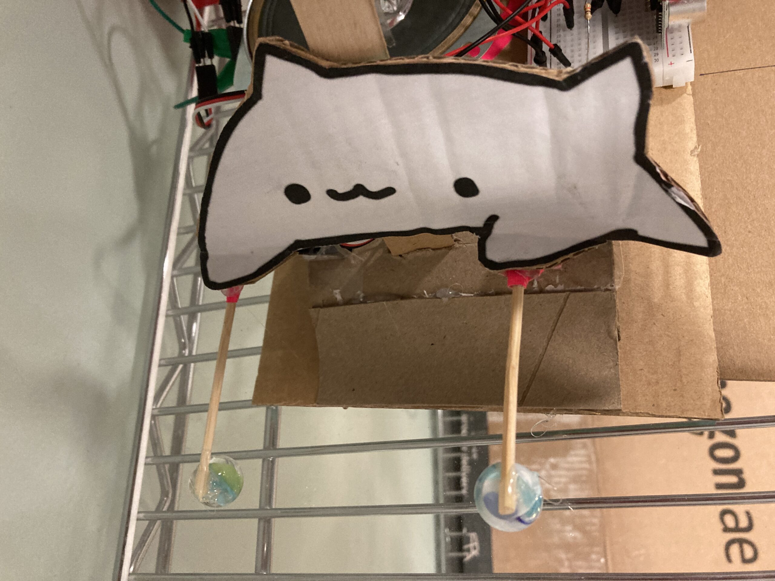
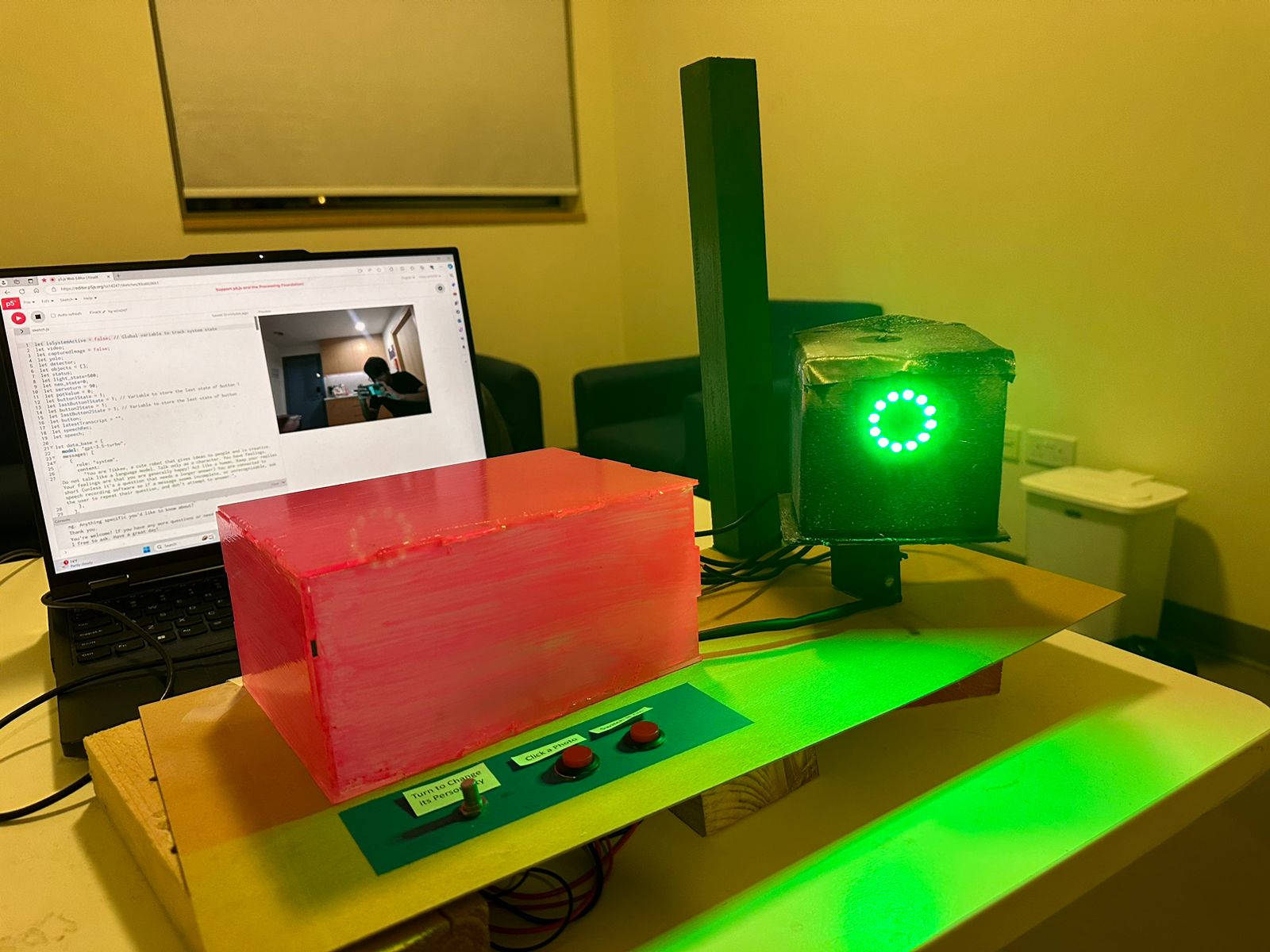
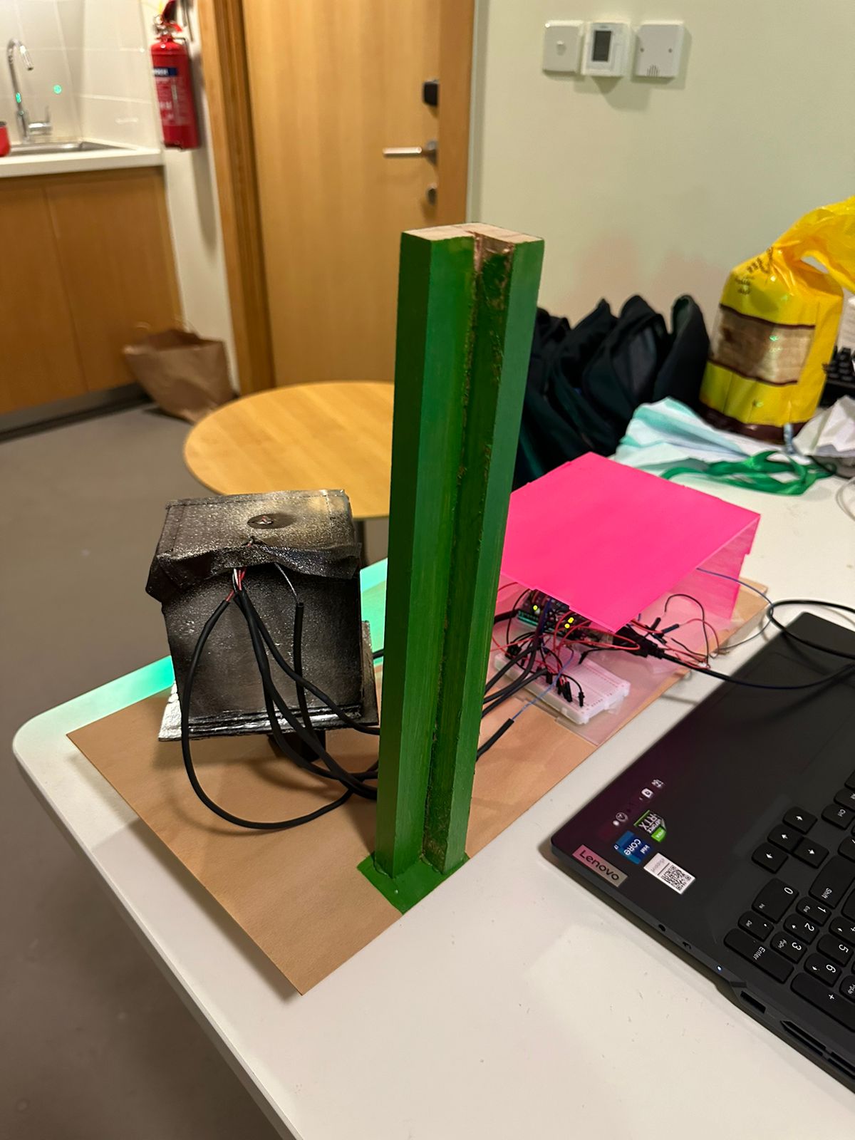
This is a project where the user can interact and communicate with a talking robot. In building this project I made extensive use of the ChatGPT API, for text generation and the p5.speech library for speech to text and text to speech. Additionally, I use the ml5.js library for person tracking that is done physically using a servo motor. Aesthetically, I was inspired by “Wall-E” to use the broken-down and creaky cardboard box aesthetic for my main moving robot head.

User Testing:

Implementation:

Interaction Design:

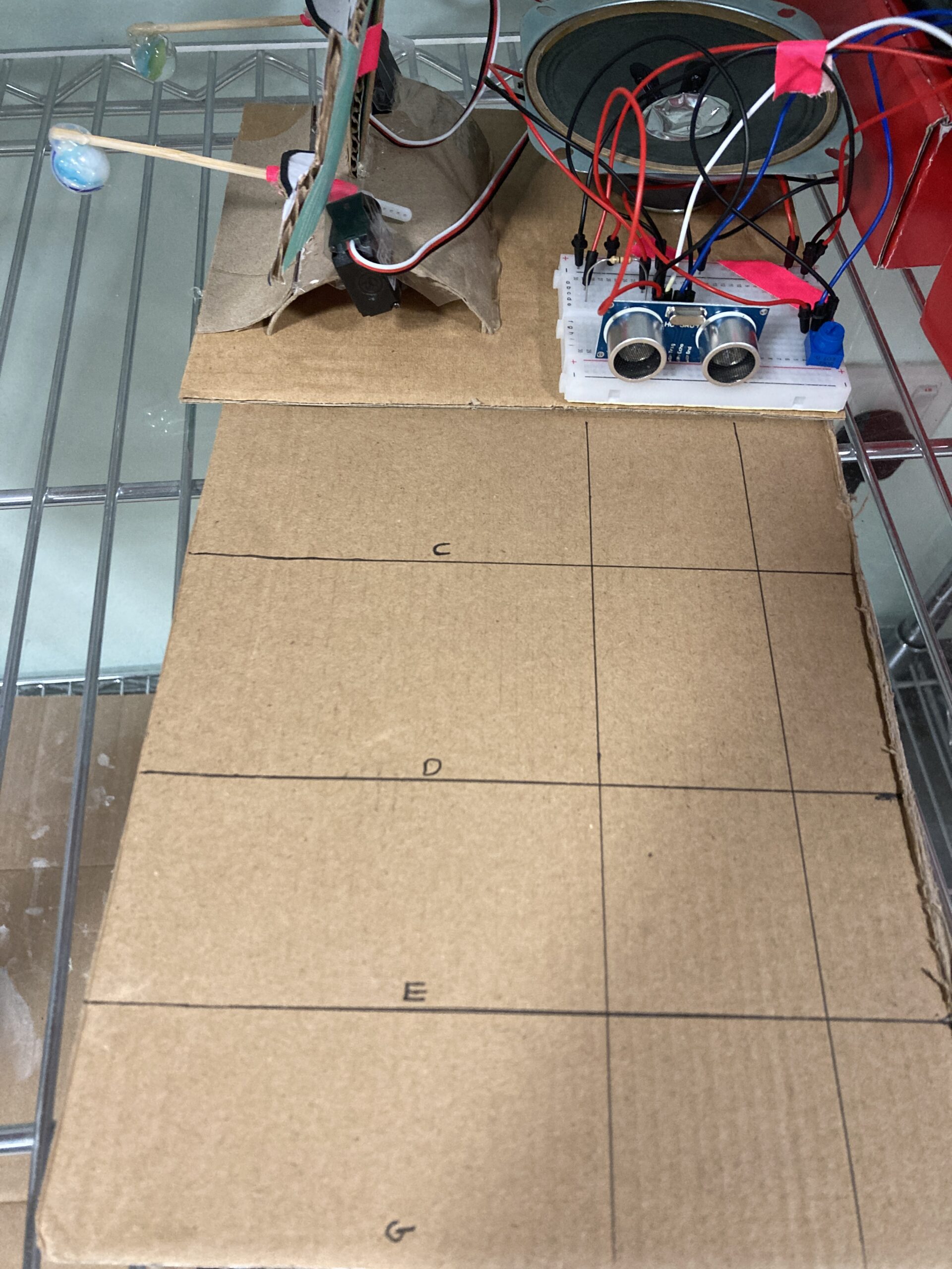
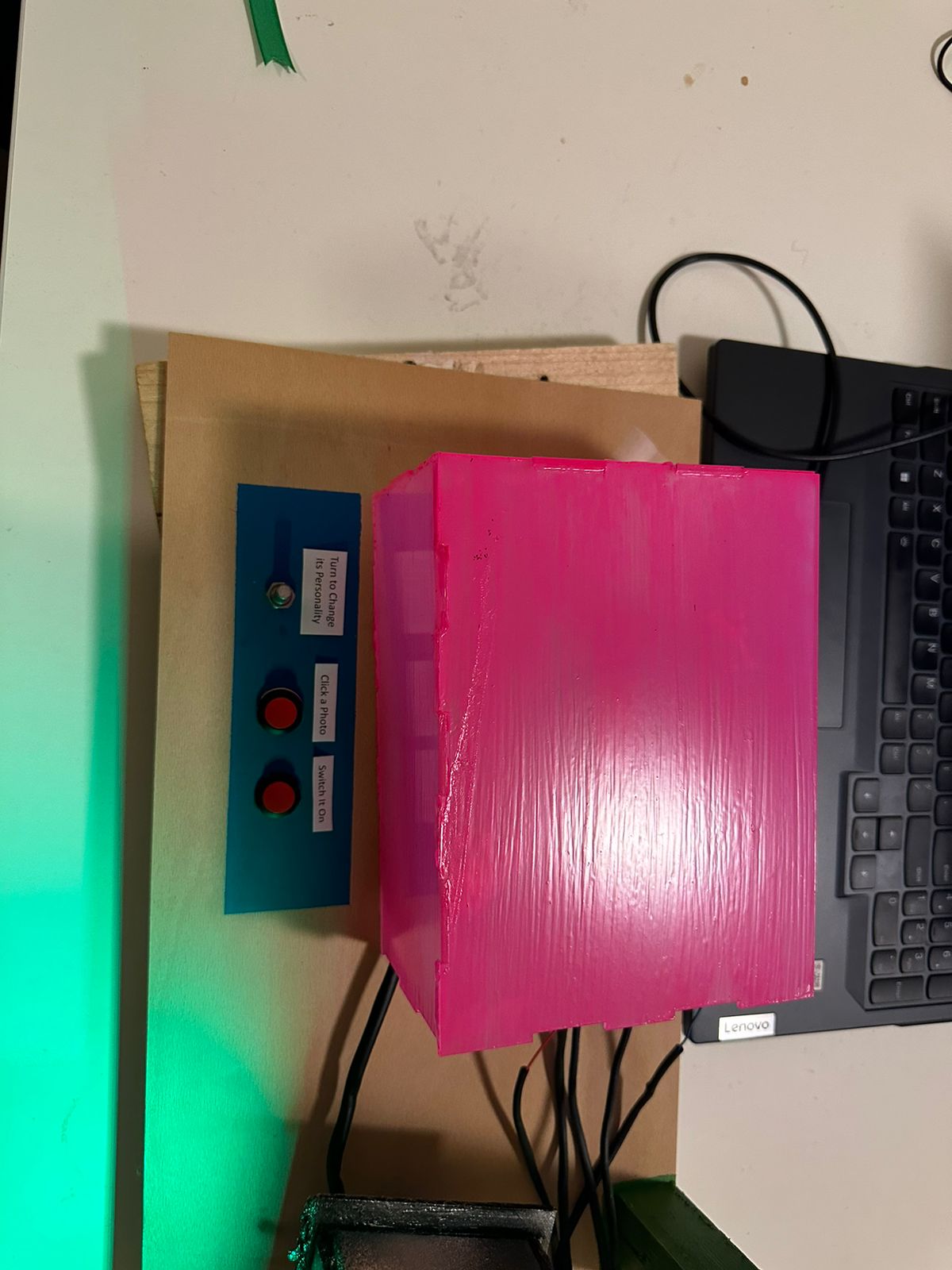
The user interacts with the robot by talking to it/moving around, patting the robot on its head, and turning a potentiometer/pressing a button. The robot tracks the user around making it seem conscious.

The talking aspect is simple, as in the robot listens to the user when the light is green, processes information when the indicator light is blue, and speaks when the indicator light is green – making it clear when the user can talk. The user can also press the “Click a photo” button and then ask a question to give the robot an image input too. Finally, the user can choose one of three possible moods for the robot – a default mode, a mode that gives the user more thoughtful answers, and a mode where the robot has an excited personality.

Arduino:

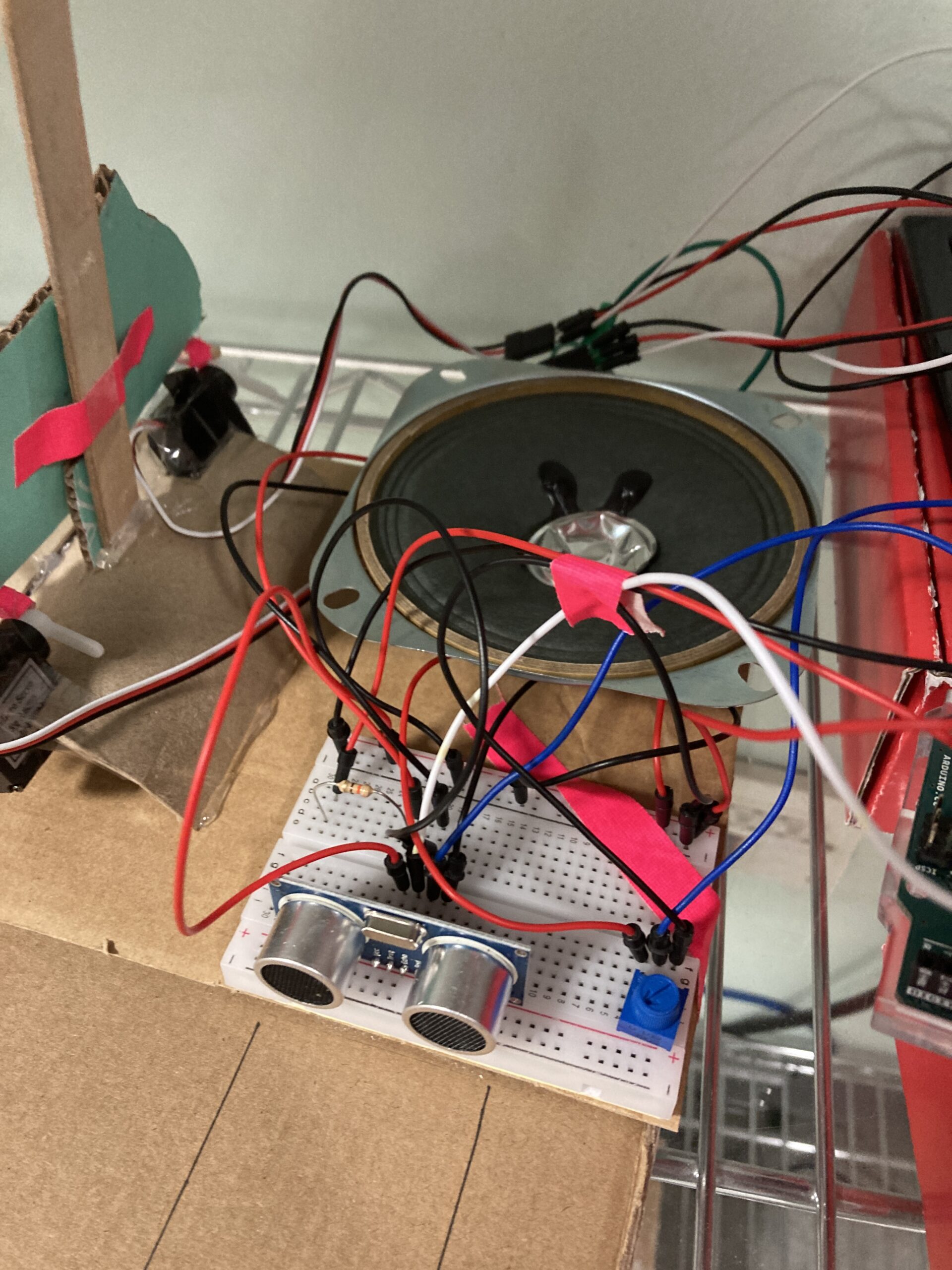
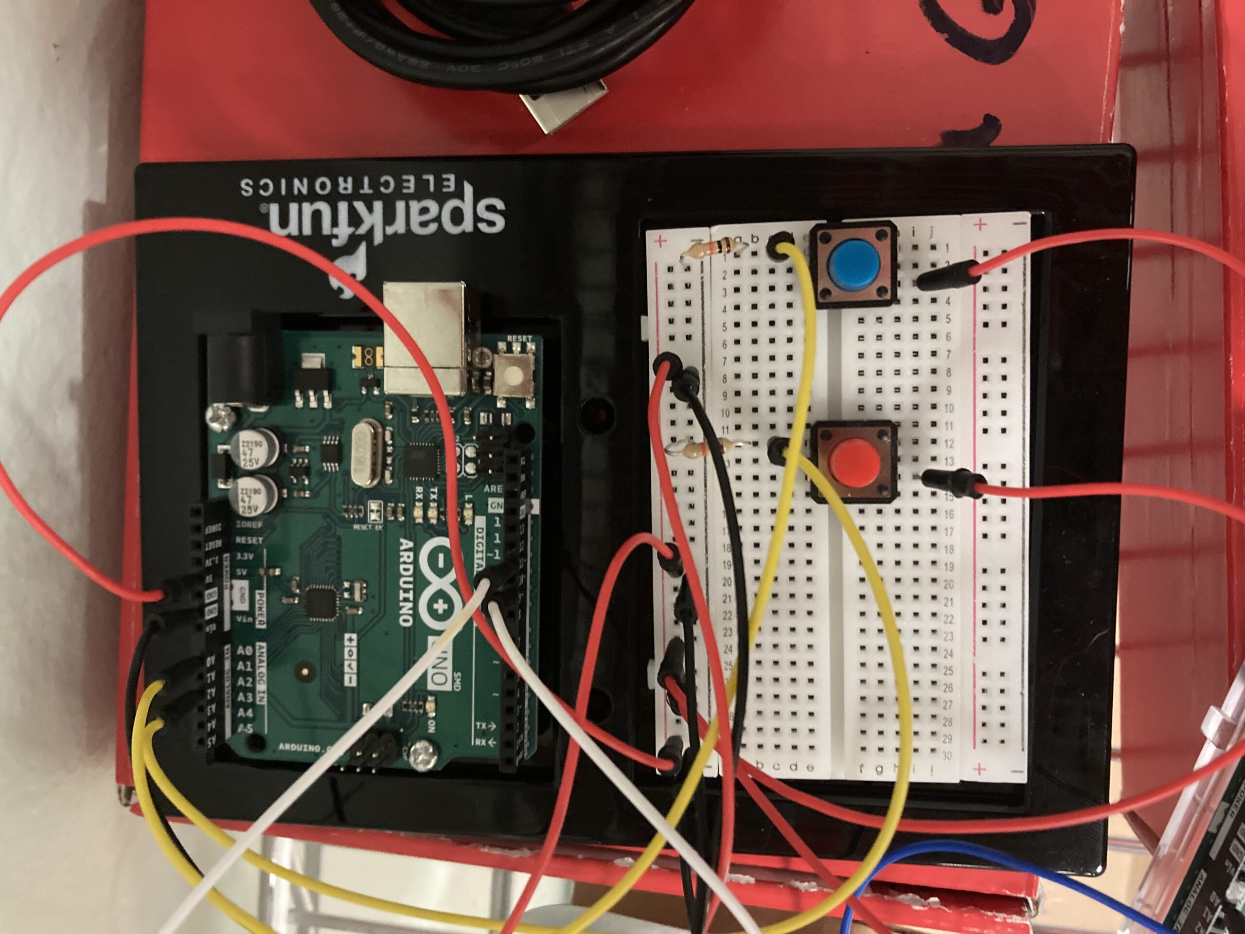
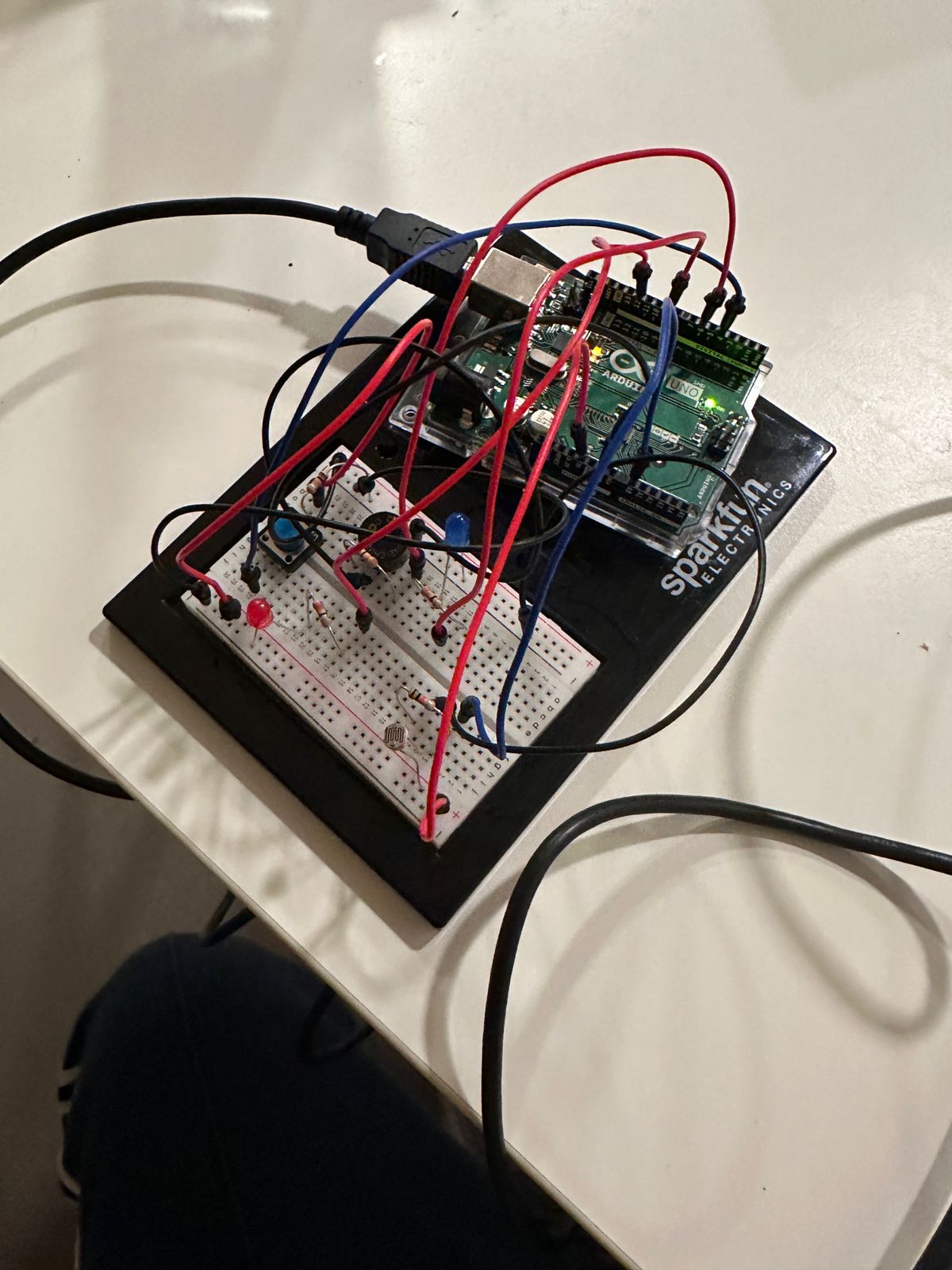
The Arduino controls the servo motor moving the robot head, the neopixels lights, the light sensor, the potentiometer and the two buttons. In terms of computations it computes what color the neopixels should be.

#include <Servo.h>
#include <Adafruit_NeoPixel.h>

// Pin where the NeoPixel is connected
#define PIN            11

// Number of NeoPixels in the strip
#define NUMPIXELS      12

// Create a NeoPixel object
Adafruit_NeoPixel strip = Adafruit_NeoPixel(NUMPIXELS, PIN, NEO_GRB + NEO_KHZ800);
Servo myservo;  // Create servo object
int pos = 90;   // Initial position
int neostate=0;
int onButton = 4;
int picButton = 7;
int potpin=A1;

void neo_decide(int neo){
  //starting
  if(neo==0)
  {
    setColorAndBrightness(strip.Color(100, 200, 50), 128); // 128 is approximately 50% of 255
    strip.show();
  }
  //listening
  else if(neo==1)
  {
    setColorAndBrightness(strip.Color(0, 255, 0), 128); // 128 is approximately 50% of 255
    strip.show();
  }
  //thinking
  else if(neo==2)
  {
    setColorAndBrightness(strip.Color(0, 128, 128), 128); // 128 is approximately 50% of 255
    strip.show();
  }
  //speaking
  else if(neo==3)
  {
    setColorAndBrightness(strip.Color(255, 0, 0), 128); // 128 is approximately 50% of 255
    strip.show();
  }
  //standby
  else
  {
    setColorAndBrightness(strip.Color(128, 0, 128), 128); // 128 is approximately 50% of 255
    strip.show();
  }
}

void setColorAndBrightness(uint32_t color, int brightness) {
  strip.setBrightness(brightness);
  for(int i = 0; i < strip.numPixels(); i++) {
    strip.setPixelColor(i, color);
    strip.show();
  }
}

void setup() {
  // Start serial communication so we can send data
  // over the USB connection to our p5js sketch
  myservo.attach(9);  // Attaches the servo on pin 9
  Serial.begin(9600);
  strip.begin();
  strip.show();
  pinMode(onButton, INPUT_PULLUP);
  pinMode(picButton, INPUT_PULLUP);
  // start the handshake
  while (Serial.available() <= 0) {
    digitalWrite(LED_BUILTIN, HIGH); // on/blink while waiting for serial data
    Serial.println("0"); // send a starting message
    delay(300);            // wait 1/3 second
    digitalWrite(LED_BUILTIN, LOW);
    delay(50);
  }
}

void loop() {
  // wait for data from p5 before doing something
  while (Serial.available()) {
    digitalWrite(LED_BUILTIN, HIGH); // led on while receiving data

    pos = Serial.parseInt();
    neostate = Serial.parseInt();
    neo_decide(neostate);
    if (Serial.read() == '\n') {
      myservo.write(pos);   // Move servo to position
      int lightstate=analogRead(A0);
      int onbuttonstate=digitalRead(onButton);
      int picbuttonstate=digitalRead(picButton);
      int potstate=analogRead(potpin);
      Serial.print(lightstate);
      Serial.print(',');
      Serial.print(potstate);
      Serial.print(',');
      Serial.print(onbuttonstate);
      Serial.print(',');
      Serial.println(picbuttonstate);
    }
  }
  digitalWrite(LED_BUILTIN, LOW);
}


P5.js

The p5.js code does most of the work for this project. Firstly, it handles the API calls to GPT3.5 Turbo and GPT-4-vision-preview models. When the user is talking to the robot normally, I send the API calls to the cheaper GPT3.5 turbo model, when the user wants to send an image input, I convert all the previously sent inputs into the format necessary for the GPT4-vision-preview model along with the image.

Second, I use the ml5.js library and the ‘cocossd’ object detection model to detect a human on the camera field of vision and draw a bounding box around it. Then we take the center of the bounding box and attempt to map the servo motor’s movement to this.

The text to speech and speech to text functionalities are done using the p5.Speech library. While doing this, we keep a track of what state we are in currently.

Lastly, we also keep track of whether the system is on right now, the light sensor’s values, and whether the click a photo button was pressed. The ‘on’ button, as the name suggests acts as a toggle for the system’s state, the light sensor starts a specific interaction when it’s value is below a threshold, and the photo button informs us about which API call to make.

Finally, we can also switch between the model’s different personalities by using the potentiometer and this is handled in the updateMood() function.


Communication between Arduino – P5

The Arduino communicates the button states, the potentiometer state, and the light sensor state to the p5.js program and receives inputs for the neopixel state, and the servo motor state.

Highlights:

For me the highlights of this project have to be designing the physical elements and handling the complex API call mechanics. Due to the fact that I use two different models that have different API input structures, the transformation between them was time-consuming to implement. Additionally, the p5.speech library that I use extensively is relatively unreliable and took a lot of attempts for me to use correctly.

Additionally, it was exciting to watch the different ways people interacted with the robot at the IM showcase. A large percent of people were interested in using the robot as a fashion guide assistant! I think overall, this was a really interesting demonstration of the potential of generative AI technology and I would love to build further using it!

Future Work:

There are several features I would love to add to this project in future iterations. Some of these include:

  • Do a basic talking animation by moving the robot’s head up and down during the talking phase. Additionally, perhaps make the robot mobile so it can move about.
  • Make the camera track the person in the front. This can be done by making the person wear a specific object – or some sophisticated ML trick.
  • Have additional interactions and add parts to the robot such as more expressive ears etc.
  • Use a more robust box and fit the arduino breadboard, camera, speaker etc. inside the robot head.
  • Make the neopixels implementation more aesthetic by employing colored patterns and animations.


Final Project – Design and Description

Concept:

The main concept of this project is to have a in-position interactive robot that can talk with, think and reply to the user. Furthermore, a conversation can influence the robot’s mood depending on which its outward interactions will change. These moods will be chosen from a series of 4-5 discrete moods. The outward movements that move include a head that turns towards the user depending on where they are talking from, ears that move when you pat them. Eyes that blink as the character talks, changing facial expressions and lights that indicate the robot’s current mood. Finally, I incorporate minimal movement using 2 DC motors.

P5 Design:

The code uses the p5.Speech library for speech recognition. the ElevenLabs API for realistic text to speech and the OpenAI ChatGPT library for text generation and reasoning. We use regular expressions to interpret the prompt engineered ChatGPT responses, and maintain a list of moods and a class that consists of actions based on every mood type. Finally, the remaining code handles the handshake mechanism between the Arduino and p5. The program will receive light sensor/distance sensor data from the Arduino, and various button related state data such as that to start a new conversation.

Arduino Design:

The Arduino design is relatively simple with Servo motors for head movement, eye blinking and facial expression changes. I use LED lights as is, but may choose to use different lights for a more aesthetic result. I use various sensors such as the light sensor on the head to get results when we attempt to pat the robot and distance/light sensors on the body to get information about how far a person’s hand/other objects are. The Arduino passes all the relevant sensor data to the p5 program and gets all relevant data from the program. Some minimal interactions such as basic ear movements or movements motivated by proximity of any sort are handled directly within the Arduino itself.

Homework – In class Assignments

Example 1:

// Map the sensor value to the width of the canvas
  ellipseX = map(latestData, 0, 1023, 0, width);

  // Draw the ellipse at the mapped position
  ellipse(ellipseX, height/2, 50, 50);

Example 2:

I simply map the mouseX coordinate to the light’s brightness!

if (mouseIsPressed) {
light=map(mouseX,0,width,0,1023);
}


Example 3:

let velocity;
let gravity;
let position;
let old_position;
let acceleration;
let wind;
let wind_arduino=0;
let drag = 0.99;
let mass = 50;
let light =0;

function setup() {
  createCanvas(640, 360);
  noFill();
  position = createVector(width/2, 0);
  velocity = createVector(0,0);
  acceleration = createVector(0,0);
  gravity = createVector(0, 0.1*mass);
  wind = createVector(0,0);
  noLoop();
}

function draw() {
  background(255);
  
  if(wind_arduino<512)
    wind.x=-1;
  else
    wind.x=1;
  applyForce(wind);
  applyForce(gravity);
  velocity.add(acceleration);
  velocity.mult(drag);
  old_position=position.y;
  position.add(velocity);
  acceleration.mult(0);
  ellipse(position.x,position.y,mass,mass);
  if (position.y > height-mass/2) {
      velocity.y *= -0.9;  // A little dampening when hitting the bottom
      position.y = height-mass/2;
    }
   print(height-mass/2);
  if (position.y >= 334)
  {
    light=1;
  }
  else
    light=0;
  if(old_position==position.y)
    light=0;
}

function applyForce(force){
  // Newton's 2nd law: F = M * A
  // or A = F / M
  let f = p5.Vector.div(force, mass);
  acceleration.add(f);
}

function keyPressed(){
  if (key==' '){
    loop();
    setUpSerial();
  }
}

// This function will be called by the web-serial library
// with each new *line* of data. The serial library reads
// the data until the newline and then gives it to us through
// this callback function
function readSerial(data) {
  ////////////////////////////////////
  //READ FROM ARDUINO HERE
  ////////////////////////////////////

  if (data != null) {
    // make sure there is actually a message
    // split the message
    let fromArduino = split(trim(data), ",");
    // if the right length, then proceed
    if (fromArduino.length == 1) {
      // only store values here
      // do everything with those values in the main draw loop
      
      // We take the string we get from Arduino and explicitly
      // convert it to a number by using int()
      // e.g. "103" becomes 103
      print(fromArduino[0]);
      wind_arduino = int(fromArduino[0]);
    }

    //////////////////////////////////
    //SEND TO ARDUINO HERE (handshake)
    //////////////////////////////////
    let sendToArduino = light+"\n";
    writeSerial(sendToArduino);
  }
}

Final Project Idea – Rob the Robot

My idea for the final project involves building a robot like character that can do simple interaction with a person in front of it. On the Arduino side, this will involve the use of several sensors such as the distance sensor, and the buttons.

This project can be as complicated as necessary and the interactions can be altered at any point.

Some example interactions include petting the robot – and it will make a sound. and talking to it.

Another interaction could be using 2 distance sensors as the eyes and then calculating an object’s distance – then using a servo motor to follow the object.

On the p5 side, I plan to use the p5.speech library that has both speech transcription and text to speech functionality. Additionally, if possible I’d like to use the ChatGPT API to generate the speech, and additionally keep track of each interaction that can be used to define the robot’s current ‘mood” -which decides the further interactions.

Weekly Reading Reflection

Design Meets Disability

Reflecting on “Design and Disability,” it’s clear that the approach to designing for disabilities is evolving. The shift from a medical to a social model highlights that disability is shaped by societal attitudes, not just medical conditions. This is exemplified by the transformation of eyewear from medical devices to fashion statements, challenging traditional views of assistive devices.

However, the integration of disability-focused design into mainstream design must be handled carefully. There’s a need to balance inclusivity with recognizing the unique needs of people with disabilities, avoiding a one-size-fits-all approach.

The role of constraints in driving innovation is also key. Design limitations, especially in disability contexts, can lead to creative, functional, and aesthetically pleasing solutions.

The reading broadens this perspective, urging us to rethink design beyond functionality, considering cultural and aesthetic impacts. Design isn’t just about creating objects; it’s about shaping cultural values and perspectives.

Lastly, design plays a crucial role in influencing societal attitudes towards disabilities. Embracing inclusive design is a step towards a more equitable society, where creativity caters to everyone’s needs. The readings collectively underscore the importance of considering both functional and societal aspects in designing for disability.

Reflections – Week 10

A Brief Rant About The Future of Interactive Design

It was fascinating to read an article about the future’s vision and direction – 12 years into the future.  Comparing Bret Victor’s ideas and complaints to what actually ended up transpiring, I am struck by both how correct he was and how much improvement is still possible.

In 2011, Victor dreamed of a future with interactivity design that involved more than just sliding and tapping on pictures behind a screen. Today, while we still continue to do  so (albeit with a few haptic gimmicks like he puts) – it is also true that we may directly be moving towards a future quite unlike this. Personally, my first experience with any kind of haptics or virtual movement simulation was the Nintendo Wii with motion detection. Today the technology has not just improved but we seem to be on the cusp of a virtual reality revolution. Virtual Reality systems have improved by leaps and bounds year upon year and soon we may reach a world where there is mainstream adoption of such technologies in everyday use.

I believe that while the future we have today would be immensely disappointing to the Bret Victor who wrote this post, the immediate future seems to be much more exciting. I am excited to see the digital future of mankind move towards a completely new direction!

Cat Composer – Week 10 Homework

Concept:

While working on this project, we went over several ideas on how we would make an instrument. One thing we discovered in our ideation process was that both of us had previously made projects that centrally involved cats. Thus, with some more tinkering around – we came up with “The Cat Composer”! The Cat Composer is an all in one musical instrument that can play a variety of simple tunes such as “Hot Cross Buns” and “Mary Had a Little Lamb”. It consists of 2 switches to control 2 beat-making servo motors, a distance sensor to control the notes (C, D, E, and G), and a turning potentiometer to toggle between octaves. Additionally, we incorporated a speaker from the IM Lab inventory to make a better sound than the provided buzzer. This instrument is best played with two people, one to play percussion/toggle between octaves, and one to play the notes.

However, with a bit of practice it is completely possible to play it by oneself! Note: In order for the distance sensor to receive a steady input and play the correct notes, it is best to play not with one’s hands, but with a larger piece of material.

Demonstration Video:

Code & Highlights:

The toughest part in the coding process was to ensure that the distance sensor worked exactly as we intended. For example, an issue that we ran into early was the abrupt changing of tune at the border values. Since the sensor isn’t accurate to the exact cm. It would then fluctuate between two tunes. We corrected this by instead using a 5-value moving average. This makes transitions significantly smoother (and the experience much more enjoyable!!)

unsigned int measureDistance() {
  const int numReadings = 5;  // Number of readings to average
  const int maxChange = 150;   // Maximum acceptable change in cm between readings
  static unsigned int lastAverage = 0;  // Store the last valid average distance
  unsigned long totalDuration = 0;


  for (int i = 0; i < numReadings; i++) {
    digitalWrite(trigPin, LOW);
    delayMicroseconds(2);
    digitalWrite(trigPin, HIGH);
    delayMicroseconds(10);
    digitalWrite(trigPin, LOW);


    totalDuration += pulseIn(echoPin, HIGH);
    delay(10); // Short delay between readings
  }


  unsigned int currentAverage = (totalDuration / numReadings) * 0.034 / 2;


  // Check if the change from the last average is within the expected range
  if (abs((int)currentAverage - (int)lastAverage) <= maxChange || lastAverage == 0) {
    lastAverage = currentAverage;  // Update the last valid average
    return currentAverage;
  } else {
    return lastAverage;  // Return the last valid average if the current reading is an outlier
  }
}

Reflections and Improvements:

We can improve our project significantly given more time!

Firstly, we would love the diversify the sounds our project can generate. In our research we discovered that instead of simply using tone() we could perhaps use some other sound generating function. We would love to try this!

Regarding the hardware implementation, the provided potentiometer is too hard to turn and often messes with the wiring. Instead we would love to use a better/larger potentiometer that allows us better access.

Similarly, another change we would like to do is to use a single Arduino Board and breadboard rather than our current 2 board solution. This will make the project more cohesive. Even though this seems easy enough to implement, we let our current design be as of now to simplify our approach.

Lastly, the ultrasonic distance sensor often gives outlier readings. As discussed in the highlight section, we tried our best to resolve this issue, however it still persists. We have some more ideas to remedy this. But we believe that given the scope of this project this was unnecessary. However, we would love to do this in the future.

Reflections – Week 9

Making Interactive Art: Set the Stage, Then Shut Up and Listen

This piece highlights the difference in making interactive art and making art. While artists (and viewers alike) generally believe that a work of art is an expression or a statement – interactive art is much different in several aspects. The artist’s role isn’t to make a statement but rather start a conversation. The viewer will then interact with this and have an experience that ideally will communicate what you want it to.

Here Tom Igoe gives practical advice as to how to make interactive art – that ultimately boils down to setting the stage, shutting up and listening to the audience. At the start of the course, this idea would have seemed foreign to me, but through both the readings and personal experiences I have come to realize what Tom intends to say here. Additionally, I love the example of the director Tom uses here, and his overall writing style!

Lastly, I believe interactive art – as the way Tom puts it – in a way serves to liberate the artist. It suggests that as an artist, one doesn’t have to bear the entire burden of meaning or impact. Instead, by creating a framework for interaction and then stepping back, an artist can allow the artwork to breathe, grow, and morph through each interaction. At the same time, it also poses a challenge: can an artist resist the urge to dictate, to instead become a facilitator of experience?

Physical Computing’s Greatest Hits (and misses)

Here Tom Igoe provides us with several examples of the kinds of physical computing works that show up frequently. Of these, I would like to reflect on 3 ideas in particular:

I particularly liked the idea of a “meditation helper”. Beyond directly building something to help with meditation. What really interests me is the concept of reading a person’s heart rate, breathing rate, etc. These factors are easily accessible these days, and it will be very interesting to build technology infused clothing that is practical and useful.

The Scooby Doo painting art type seems overdone but something about it still remains intensely creepy. I would love to incorporate something of that manner in a project I do going forwards.

Lastly, floor pads are also exciting. I am curious as to if we can somehow engineer them in a way that lets us walk in place (like a treadmill and have that actually simulate a walk for a character in real-time etc. Moreover, there’s a lot more that can be done with such pads if we keep adding layers of complexity!

The Nightlight and the Alarm

Approach and Concept:

It took me a long time to come up with the idea for this project given the requirements it had. But at the end of our previous lecture, I realized I could make a night-light+morning alarm system.

For my analog input I use the light sensor we employed in class. In the morning, this turns on the buzzer (digital output 1) and the red LED light( digital output 2). While it’s night (low light) the blue LED (analog output) blinks in a slow and satisfying manner. A button (digital input switch) can be used to turn the whole system off or on at any given time.

I believe this whole system, if refined further a bit has actual practical utility, and I’m really happy I could make something like this on my own!

Highlights:

I would like to highlight both the coding and the hardware work for this project:

Coding: The system uses a state management system. When I tried to use code from the examples we used in the lecture. This became complicated because doing things like making the analog output led blink slowly couldn’t be done through for loops – or the delay would mess up with the state switching mechanism. To navigate through this, I had to remove the for loops and instead work directly with the loop function. Similarly, I faced this issue again with the buzzer where the delay’s blocking nature was causing some problems – leading me to use the external ezBuzzer library. Beyond this, joining together so many components itself was a fun challenge!

void loop() {
  buzzer.loop();
  // read the state of the pushbutton value:
  buttonState = digitalRead(buttonPin);
  int analogValue = analogRead(A0);
  // check if the pushbutton is pressed. If it is, the buttonState is HIGH:
  if (buttonState == HIGH && led_state==0) {
    while(buttonState==HIGH)
    {
      buttonState = digitalRead(buttonPin);
    // turn LED on:
      led_state=1;
    }
  }
  else if(buttonState == HIGH && led_state==1)
  {
    while(buttonState ==HIGH)
    {
      buttonState = digitalRead(buttonPin);
      led_state=0;
    }
  }
  Serial.println(led_state);
  digitalWrite(ledPin,led_state && led_stateD);
  if(led_state==0 || led_stateD==0)
  {
    if (buzzer.getState() != BUZZER_IDLE) {
      buzzer.stop() ; // stop
    }
  }
  else 
  { if (buzzer.getState() == BUZZER_IDLE) {
      int length = sizeof(noteDurations) / sizeof(int);
      buzzer.playMelody(melody, noteDurations, length); // playing
    }
  }
  if (analogValue < 300) {

    led_stateD=0;
    led_stateA=1;
  }
  else {
    led_stateD=1;
    led_stateA=0;
  }
  if(led_state==1 && led_stateA){
  // fade in from min to max in increments of 5 points:
  if(millis()%10==0) {
    // sets the value (range from 0 to 255):
    fadeValue+=increment;
    analogWrite(ledPinAnalog, fadeValue);
    if (fadeValue==255 || fadeValue==0)
      increment*=-1;
  }}
  if(led_state==0 ||led_stateA==0)
    analogWrite(ledPinAnalog, 0);

}


Hardware: The connections itself were simple enough in themselves – since I had knowledge of what we had done in class to borrow from. However, given the many elements the board itself got messy – making navigation a hassle.

Reflections and Future Work:

There are several improvements I would like to make on this work. On the technical implementation aspect, I can possible manage the wires I use much better than I have done here. And on the coding aspect, the code can definitely be made more streamlined and easier to read.

In terms of future work, I would like to add more lights to the nightlight aspect, and make the blinking pattern more complex to have a more soothing experience. Similarly, the buzzer noise and the morning alarms can also be improved aesthetically. In terms of functionality, it would be nice to have another button than can function as a snooze button.


Blink and You Miss it

Approach and Concept:

After spending a lot of time brainstorming ideas – I found one I was particularly proud of. The phrases “it happened in the blink of an eye “, “blink and you miss it” etc. are often used to talk about phenomena that happen really quickly. The literal meaning behind them is that it may as well happen that the phenomenon will start and end in the time it takes for you to finish a blink – leaving you with nothing to observe.

So how about we build a system that only does ‘something’ when you close your eyes? Thus now, every time you blink, or close your eyes – you miss ‘it’. You never actually have the experience but everyone around you does. I was personally satisfied with the concept but it was quite difficult to actually implement it given the very limited range of motion of our eyelids. Nonetheless, I ended up succeeding in doing so:

The mechanism that connects the switch to the eyelid movement. (double sided tape connects the thread to your eyelid. a piece of cardboard covered with aluminum foil and weighed down further using a coin serves as the conducting bridge.)

The simplified circuit

The switchboard. Two wires are taped to a piece of cardboard and aluminum foil is used to increase the surface area of conduction.

Demonstration:

Highlights:

The part I’m the most proud of in this project is devising the exact mechanism for the switch to work. Unlike the p5.js coding assignments, arduino and physical hardware is something I have no experience in – so this was my first time actually working with these elements and I had a lot of fun finding solutions to problems as they came up.

For example, just taping the wires to the cardboard and using the aluminum foil as the switch worked – but it wasn’t as reliable due to the uncertain points of contact between the wire ends and the foil. I managed to remedy this by putting a layer of aluminum foil on the wire ends.

Next, the switch mechanism itself didn’t have enough weight so it wouldn’t rest properly on the wire ends. I changed this by putting a small coin as to add some weight to the mechanism – and this ended up working spectacularly.

Reflections and Future Work:

I’m proud of several decisions I made in the design of this switch as I stressed earlier. However, there are quite a few things I would do differently if I had to redo the project:

First, I would find a more effective way to connect my eyelids to the switch. The current method using double-sided tape works but is very inefficient. I am still unsure as to how I would do this though.

Second, the switch itself is fairly robust to perturbations – but I believe it can be improved further aesthetically and functionally. I can use a more stable base and find better configurations to place the aluminum foil such that it covers the best area possible.

Lastly, since all my time was spent focusing on the switch, my actual design for the lights can definitely improve by a lot. I would like to add more LEDs to make my design prettier.