Final Project Documentation

Concept

The Smart House System is an interactive physical computing project that simulates features of an intelligent home using Arduino UNO and p5.js. The system includes:

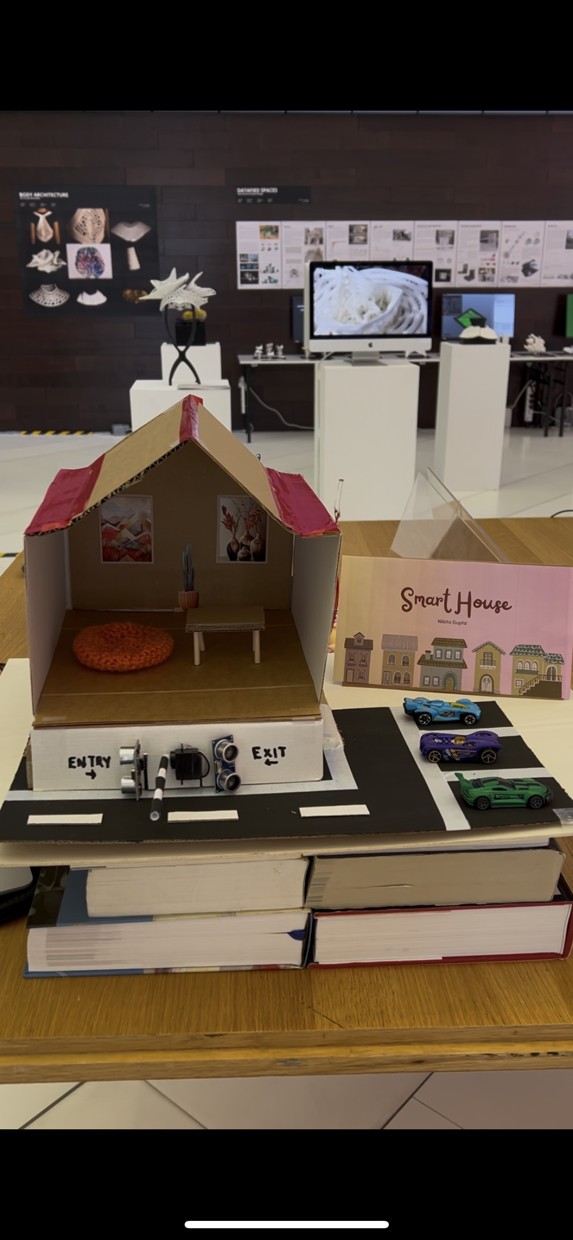
  • A smart parking assistant that detects cars entering and exiting, and updates available parking slots automatically.

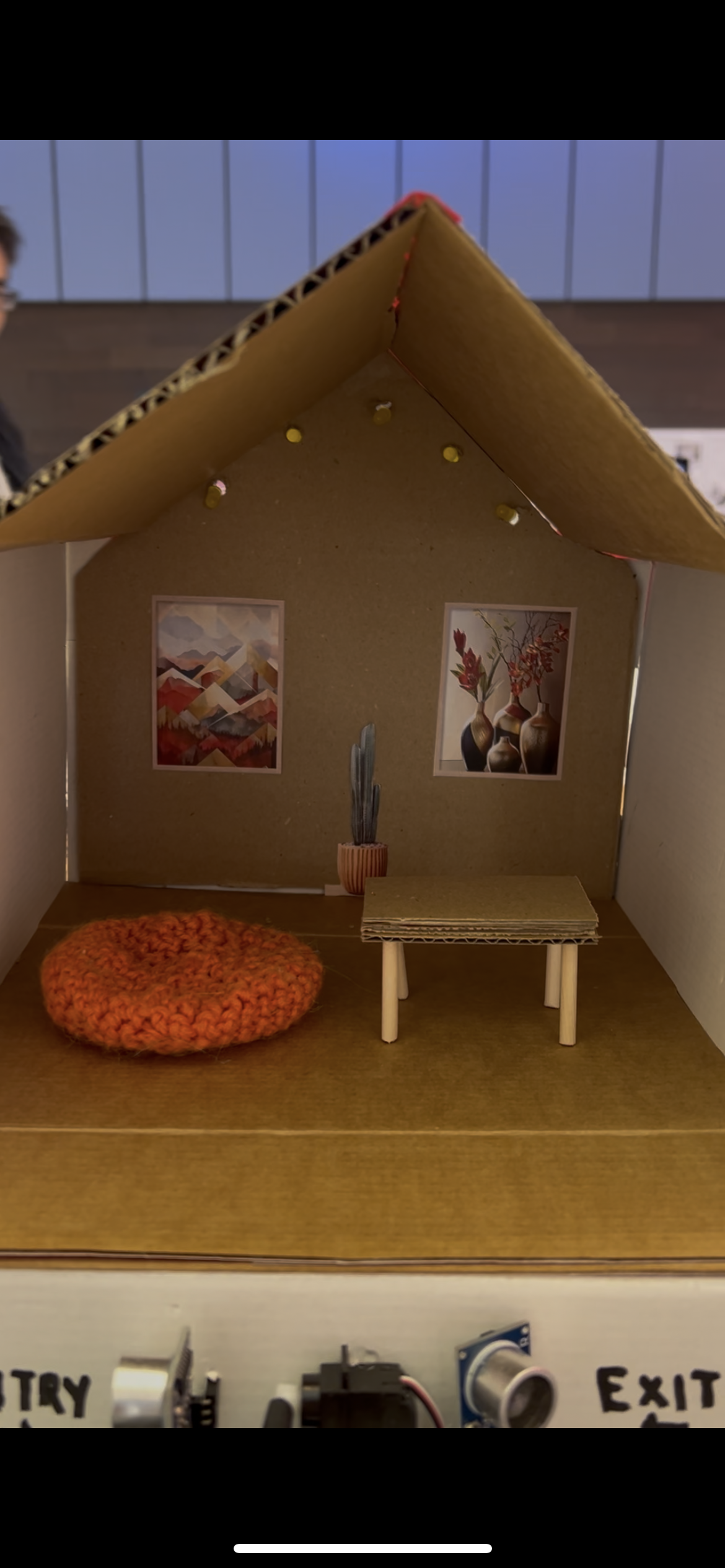
  • A light automation system that turns on indoor lights when it gets dark, based on ambient light readings.

  • A real-time dashboard and voice announcer, implemented in p5.js, that visualizes the system state and speaks updates aloud using p5.speech.

This system provides a fun and engaging way to demonstrate real-world home automation, combining sensors, outputs, and visual/voice feedback for user interaction.

Interaction Demo

IMG_9078

How the Implementation Works

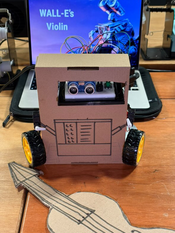
The system uses ultrasonic distance sensors to detect when a vehicle is near the entry or exit of the parking area. A servo motor simulates the gate that opens when a car arrives and parking is available.

A photoresistor (LDR) detects light levels to automatically turn on five LEDs that simulate indoor lighting when it gets dark.

All event messages from Arduino are sent to a p5.js sketch over web serial. The browser-based sketch then:

  • Displays the parking status

  • Shows light status

  • Uses p5.speech to speak real-time messages like “Parking is full!” or “Lights are now on!”

Interaction Design

The project is designed for simple, touchless interaction using real-world analog sensors:

  • Bringing your hand or an object close to the entry sensor simulates a car arriving. If space is available, the gate opens, the slot count is reduced, and a voice announces the update.

  • Moving your hand in front of the exit sensor simulates a car leaving, increasing the parking availability.

  • Covering the LDR sensor simulates nighttime — lights automatically turn on, and the system announces it.

  • The p5.js dashboard shows real-time status and acts as an interactive voice feedback system.

Arduino Code

The Arduino UNO is responsible for:

  • Reading two ultrasonic sensors for car entry/exit

  • Reading the photoresistor (LDR) for light level

  • Controlling a servo motor for the gate

  • Controlling 5 indoor LEDs

  • Sending status messages to the p5.js sketch over serial

Code Overview:

  • Starts with 3 available parking slots

  • Gate opens and slot count decreases when a car is detected at entry

  • Slot count increases when a car exits

  • Indoor lights turn on when light level drops below a threshold

  • Sends messages like car_entry, car_exit, parking_full, lights_on, lights_off, and parking_spots:X

#include <Servo.h>

// Ultrasonic sensor pins
#define trigEntry 2
#define echoEntry 3
#define trigExit 4
#define echoExit 5

// Servo motor pin
#define servoPin 6

// LED pins
int ledPins[] = {7, 8, 9, 10, 11};

// Light sensor pin
#define lightSensor A0

Servo gateServo;
int Slot = 3; // Initial parking spots

void setup() {
  Serial.begin(9600);

  // Ultrasonic sensors
  pinMode(trigEntry, OUTPUT);
  pinMode(echoEntry, INPUT);
  pinMode(trigExit, OUTPUT);
  pinMode(echoExit, INPUT);

  // LED pins
  for (int i = 0; i < 5; i++) {
    pinMode(ledPins[i], OUTPUT);
  }

  // LDR analog input
  pinMode(lightSensor, INPUT);

  // Servo
  gateServo.attach(servoPin);
  gateServo.write(100); // Gate closed
}

void loop() {
  int entryDistance = getDistance(trigEntry, echoEntry);
  int exitDistance  = getDistance(trigExit, echoExit);
  int lightValue    = analogRead(lightSensor); // 0 (dark) to 1023 (bright)

  Serial.print("Entry: "); Serial.print(entryDistance);
  Serial.print(" | Exit: "); Serial.print(exitDistance);
  Serial.print(" | Light: "); Serial.print(lightValue);
  Serial.print(" | Slots: "); Serial.println(Slot);

  // ===== Car Entry Logic =====
  if (entryDistance < 10 && Slot > 0) {
    openGate();
    Slot--;
    Serial.println("car_entry");
    Serial.print("parking_spots:");
    Serial.println(Slot);
    delay(2000);
    closeGate();
  }
  // ===== Parking Full Logic =====
  else if (entryDistance < 10 && Slot == 0) {
    Serial.println("parking_full");
    delay(1000); // Prevent spamming the message
  }

  // ===== Car Exit Logic =====
  if (exitDistance < 10 && Slot < 3) {
    openGate();
    Slot++;
    Serial.println("car_exit");
    Serial.print("parking_spots:");
    Serial.println(Slot);
    delay(2000);
    closeGate();
  }

  // ===== Light Control (5 LEDs) =====
  if (lightValue < 900) { // It's dark
    for (int i = 0; i < 5; i++) {
      digitalWrite(ledPins[i], HIGH);
    }
    Serial.println("lights_on");
  } else {
    for (int i = 0; i < 5; i++) {
      digitalWrite(ledPins[i], LOW);
    }
    Serial.println("lights_off");
  }

  delay(500);
}

// ===== Gate Functions =====
void openGate() {
  gateServo.write(0);
  delay(1000);
}

void closeGate() {
  gateServo.write(100);
  delay(1000);
}

// ===== Distance Sensor Function =====
int getDistance(int trigPin, int echoPin) {
  digitalWrite(trigPin, LOW);
  delayMicroseconds(2);
  digitalWrite(trigPin, HIGH);
  delayMicroseconds(10);
  digitalWrite(trigPin, LOW);
  long duration = pulseIn(echoPin, HIGH);
  int distance = duration * 0.034 / 2;
  return distance;
}

Circuit Schematic

p5.js Code and Dashboard

The p5.js sketch:

  • Uses the p5.webserial library to connect to Arduino

  • Uses p5.speech for voice announcements

  • Displays a dashboard showing the number of available parking slots

  • Shows the indoor light status using a colored circle

The voice announcements are fun and slightly humorous, e.g.:

“A wild car appears!”
“Uh-oh! Parking is full.”
“It’s getting spooky in here… turning the lights on!”

The sketch uses a say() wrapper function to safely trigger voice output in Chrome after the user clicks once.

Code Highlights:

  • Automatically resumes Chrome’s audio context

  • Waits for user interaction before enabling speech

  • Processes serial messages one line at a time

  • Provides a Connect/Disconnect button for user control

Arduino and p5.js Communication

The communication uses Web Serial API via p5.webserial:

  • Arduino sends messages like "car_entry\n", "lights_on\n", etc.

  • p5.js reads each line, processes it, updates the dashboard, and speaks it out loud

  • A connect button in the sketch allows users to select their Arduino port manually

  • All communication is unidirectional: Arduino → p5.js

What I’m Proud Of

  • Fully working sensor-triggered voice feedback via p5.js — makes the system feel alive

  • Smooth parking logic with entry and exit detection

  • Integration of multiple Arduino components (servo, LDR, LEDs, ultrasonic)

  • An intuitive UI that works both visually and with voice

  • Reliable browser-based connection using modern Web Serial

Areas for Future Improvement

  • Add a screen-based parking spot display (e.g., 7-segment or OLED)

  • Use non-blocking code in Arduino with millis() instead of delay()

  • Make a mobile-responsive version of the dashboard UI

  • Add a security camera feed or face detection in p5.js

  • Improve the servo animation to be smoother and time-synced

  • Add a buzzer or alert when parking is full

Week 12: Final Project Proposal

Smart House System

For this project, I am designing a Smart House System using Arduino UNO and p5.js.
The idea was to automate key parts of a house and parking lot, and to create a more interactive experience using voice announcements made with p5.js.

The main features include:

  • Automatic main door that opens when a person approaches.

  • Car parking system that displays the number of available spots and automatically opens a parking barricade if spots are available.

  • Indoor lighting system that switches on when it gets dark, based on a photoresistor sensor.

  • Real-time voice announcements generated in p5.js based on Arduino sensor inputs, to make the system feel alive and responsive during an exhibition demo.

Design and Description of Arduino Program

The Arduino is responsible for all hardware sensor readings, actuator controls, and sending/receiving messages to and from p5.js.

Component Type Description
Distance Sensor (Main Door) Input Measures distance to detect a visitor near the main door.
Distance Sensor (Parking Entrance) Input Detects a car approaching the parking gate (entry).
Distance Sensor (Parking Exit) Input Detects a car leaving the parking area (exit).
Photoresistor (Indoor Lighting) Input Detects ambient light levels to determine if indoor lights should be turned on.
Servo Motor (Main Door) Output Opens or closes the main entrance door based on visitor detection.
Servo Motor (Parking Gate) Output Opens or closes the parking barricade when a car is allowed entry.
LED Display Output Shows the number of parking spots left.
Indoor LEDs / Lights Output Turns indoor lights on/off based on photoresistor readings.

Design and Description of p5.js Program

The p5.js program is responsible for interaction, feedback, and visualization.

Main Tasks:

  • Connects to Arduino through Serial communication.

  • Reads messages sent from Arduino (e.g., “door_open”, “lights_on”, “parking_spots:3”).

  • Plays real-time voice announcements using the p5.speech library based on events detected.

  • Displays a virtual dashboard showing the current number of available parking spots and statuses like door open/closed, lights on/off.

Voice Announcements Based on Arduino Events:

Arduino Message p5.js Voice Announcement
door_open “Welcome! The door is opening.”
car_entry “Vehicle detected. Checking parking availability.”
car_exit “Vehicle exited. Parking spot now available.”
parking_full “Parking is full. Please wait.”
lights_on “Lights are now on for your comfort.”
lights_off “Lights are off to save energy.”

Week 11: Design meets Disability

In Design Meets Disability, Graham Pullin talks about how design and disability don’t have to be separate things. He makes the point that products for people with disabilities are often made just to be functional, not stylish or personal. But he believes design should consider both usefulness and aesthetics. For example, he compares hearing aids to glasses—how glasses have become a fashion item, while hearing aids are still usually hidden. This really made me think about how much design influences how people feel about themselves and their devices.

What stood out to me is how Pullin encourages designers to think differently and challenge old assumptions. Instead of just trying to make something look “normal,” why not celebrate individuality and make things that people are proud to use? It made me realize how much power design has—not just in how things work, but in how they make people feel. Overall, the reading made me think more deeply about what inclusive design really means and how it can actually improve lives in more ways than just solving a problem.

Week 11: Final Project Idea

Concept:
My final project is a physically interactive zombie shooting game that uses a laser pointer and photoresistors (light sensors) to detect hits. The player uses a toy gun or pointer that emits a laser beam to “shoot” zombies that appear randomly. On a physical board, multiple photoresistors are positioned with LEDs next to them, each representing a zombie spawn point. When a zombie appears, an LED lights up, and the player must aim the laser pointer at that sensor to “kill” the zombie. The interaction is fast-paced and relies on quick aiming and physical movement, combining real-world action with digital feedback.


Arduino’s Role:
The Arduino is responsible for controlling the game logic on the hardware side. It randomly selects which LED to turn on, simulating a zombie “appearing” in that location. It continuously reads data from the photoresistors to detect when a laser beam hits the correct sensor. When a hit is detected, the Arduino confirms the zombie has been shot, turns off the LED, and sends the information to P5.js (such as which zombie was hit and the reaction time). It can also keep track of hits and misses, and control the timing of zombie spawns to make the game more challenging as it progresses.


P5.js Display:
P5.js will serve as the visual part of the game, showing animated zombies that match the LEDs lighting up on the physical board. When the Arduino tells P5 a zombie has appeared (LED turned on), a zombie image will pop up in the corresponding location on the screen. When the player successfully shoots the sensor with the laser, the zombie will disappear with a simple animation, like falling down or exploding. The game will display the player’s score, reaction time for each shot, and lives or missed zombies. It can also play sound effects for hits and misses, and include a game over screen when the player fails to shoot zombies in time.

Week 11: Serial Communication

Arduino & p5.js

[Nikita and Genesis]

Each exercise focuses on the communication between the Arduino’s physical components and visual output through serial communication.


Exercise 1: Moving an Ellipse with One Sensor

video

Arduino Code:

void setup(){
 Serial.begin(9600);
}
void loop(){
 int pot = analogRead(A0);
 // send mapped X (0–400) to p5
 int xPos = map(pot, 0, 1023, 0, 400);
 Serial.println(xPos);
 delay(30);
}

circuit:

Explanation:

This exercise uses a single analog sensor (potentiometer) connected to Arduino to control the horizontal position of an ellipse in p5.js. The Arduino reads the potentiometer value and sends it over Serial to the p5.js sketch, which updates the x-position of the ellipse accordingly. The communication is one-way:   Arduino → p5.js.


Exercise 2: Controlling LED Brightness from p5.js

video

Arduino Code:

// Arduino: LED brightness via Serial.parseInt()
const int ledPin = 9; // PWM-capable pin


void setup() {
 pinMode(ledPin, OUTPUT);
 Serial.begin(9600); 
}


void loop() {
 if (Serial.available() > 0) {
   int brightness = Serial.parseInt(); // Read integer from serial
   brightness = constrain(brightness, 0, 255); // Clamp
   analogWrite(ledPin, brightness);
 }
}

circuit:

Explanation:

In this exercise, the communication is reversed. The p5.js sketch sends a brightness value (0–255) to Arduino via Serial, which adjusts the brightness of an LED connected to a PWM-capable pin (pin 9). This demonstrates real-time control from software (p5.js) to hardware (Arduino).


Exercise 3: Gravity Wind with LED Bounce Indicator

video

Arduino Code:

/*
* Exercise 3 Arduino:
* - Read pot on A0, send sensorValue to p5.js
* - Listen for 'B' from p5.js → blink LED on pin 9
*/
const int sensorPin = A0;
const int ledPin    = 9;


void setup() {
 Serial.begin(9600);       
 pinMode(ledPin, OUTPUT);
}


void loop() {
 // Read and send sensor
 int sensorValue = analogRead(sensorPin);
 Serial.println(sensorValue);


 // Check for bounce command
 if (Serial.available() > 0) {
   char inChar = Serial.read();
   if (inChar == 'B') {
     digitalWrite(ledPin, HIGH);
     delay(100);
     digitalWrite(ledPin, LOW);
   }
 }


 delay(20);
}

circuit:

Explanation:

This sketch is a modified version of the classic p5.js Gravity + Wind example. An analog sensor (potentiometer) on Arduino controls the wind force in p5.js. Every time the ball hits the bottom (a “bounce”), p5.js sends a command (‘B’) back to Arduino via Serial, which briefly lights up an LED. This showcases a complete two-way communication system between Arduino and p5.js.


Week 10: Follow-up article

Going through the responses to Victor’s rant, I found it interesting how many people agreed with the idea that touchscreens are a dead end, but still struggled to imagine what a better alternative would look like. It’s almost like we all know something is missing, but we’re too deep inside the current system to clearly picture a different path. I noticed some people pointed to things like haptic feedback or VR as potential improvements, but even those seem to stay within the same basic mindset — still about looking at and manipulating screens, just in fancier ways. It made me realize how hard it is to break out of an existing mental model once it becomes the norm.

What also stood out to me is that a lot of the responses weren’t dismissive or defensive — they were actually pretty hopeful. Even though Victor’s tone was a bit harsh in the original rant, the responses seemed to take it as a genuine challenge rather than just criticism. That feels important, because it shows that many designers do want to think bigger; they just need help finding new tools or ways of thinking. It made me think that maybe progress in interaction design isn’t about inventing some magic new device overnight, but about slowly shifting how we even define interaction in the first place.

Week 10: A Brief Rant on the Future of Interaction Design

As I was reading A Brief Rant on the Future of Interaction Design, what really struck me was how much we’ve just accepted the idea that “the future” means shiny screens everywhere. Bret Victor makes a strong point that even though technology looks cooler and sleeker, the way we interact with it hasn’t fundamentally changed — it’s still just tapping and swiping on glass. It’s kind of depressing when you think about it, because the excitement around “new technology” mostly ignores the fact that humans are physical, three-dimensional beings. We have hands that are capable of so much subtlety, but all we do is poke at flat rectangles. Victor’s frustration feels justified — it’s like we’ve totally surrendered to convenience at the cost of creativity and human potential.

At the same time, I found myself wondering: is it really fair to expect interaction design to be radically different when so much of our world (work, entertainment, communication) has moved into the digital space? Maybe part of the reason we keep using screens is because they’re the simplest way to deal with abstract information. But still, Victor’s examples of more tactile, nuanced designs made me realize we’re probably limiting ourselves by not even trying to imagine alternatives. It’s like we’re stuck optimizing what already exists instead of exploring what could be fundamentally new. After reading this, I feel like a good interaction designer shouldn’t just make apps easier to use, but should rethink what “using” even means.

Week 10: Musical Instrument

Concept:

video

“WALL-E’s Violin” is inspired by the character WALL-E from the popular animated movie. The idea behind “WALL-E’s Violin” is to mimic WALL-E expressing emotion through music, specifically through a violin — a symbol of sadness and nostalgia. A cardboard model of WALL-E is built with an ultrasonic distance sensor acting as his eyes. A cardboard cutout of a violin and bow are placed in front of WALL-E to represent him holding and playing the instrument. 

As the user moves the cardboard stick (the “bow”) left and right in front of WALL-E’s “eyes” (the ultrasonic sensor), the sensor detects the distance of the bow. Based on the distance readings, different predefined musical notes are played through a piezo buzzer. These notes are chosen for their slightly melancholic tones, capturing the emotional essence of WALL-E’s character.

To add a layer of animation and personality, a push-button is included. When pressed, it activates two servo motors attached to WALL-E’s sides, making his cardboard arms move as if he is emotionally waving or playing along. The mechanical hum of the servos blends into the soundscape, enhancing the feeling of a robot expressing music not just through tones, but with motion — like a heartfelt performance from a lonely machine.

How it Works:

  • Ultrasonic Sensor: Acts as WALL-E’s eyes. It continuously measures the distance between the robot and the cardboard bow moved in front of it.
  • Note Mapping: The Arduino interprets the measured distances and maps them to specific, predefined musical notes. These notes are chosen to sound melancholic and emotional, fitting WALL-E’s character.
  • Piezo Buzzer: Plays the corresponding musical notes as determined by the distance readings. As the user sways the bow, the pitch changes in real time, simulating a violin being played.
  • Servo Motors + Button: Two servo motors are connected to WALL-E’s arms. When the button is pressed, they animate his arms in a waving or playing motion. The sound of the servos adds a robotic texture to the performance, further humanizing the character and blending physical movement with audio expression.

Code:

#include <Servo.h>
#include <math.h>

// Pin Assignments

const int trigPin   = 12;   // Ultrasonic sensor trigger
const int echoPin   = 11;   // Ultrasonic sensor echo
const int buzzerPin = 8;    // Buzzer output
const int buttonPin = 2;    // Button input for servo tap
const int servoPin  = 9;    // First servo control pin (default starts at 0°)
const int servoPin2 = 7;    // Second servo control pin (default starts at 180°)

Servo myServo;    // First servo instance
Servo myServo2;   // Second servo instance

// Bittersweet Melody Settings

int melody[] = {
  294, 294, 370, 392, 440, 392, 370, 294
};
const int notesCount = sizeof(melody) / sizeof(melody[0]);


// Sensor to Note Mapping Parameters

const int sensorMin = 2;     // minimum distance (cm)
const int sensorMax = 30;    // max distance (cm)
int currentNoteIndex = 0;  

// Vibrato Parameters 

const float vibratoFrequency = 4.0;  
const int vibratoDepth = 2;          

// Timer for vibrato modulation

unsigned long noteStartTime = 0;

void setup() {
  // Initialize sensor pins
  pinMode(trigPin, OUTPUT);
  pinMode(echoPin, INPUT);
  
 // Initialize output pins
  pinMode(buzzerPin, OUTPUT);
  pinMode(buttonPin, INPUT_PULLUP);  
  
  // Initialize the first servo and set it to 0°.
  myServo.attach(servoPin);
  myServo.write(0);
  
   // Initialize the second servo and set it to 180°..
  myServo2.attach(servoPin2);
  myServo2.write(180);
  
 // Initialize serial communication for debugging
  Serial.begin(9600);
  
// Get the initial note based on the sensor reading
  currentNoteIndex = getNoteIndex();
  noteStartTime = millis();
}

void loop() {
 // Get the new note index from the sensor
  int newIndex = getNoteIndex();
  
 // Only update the note if the sensor reading maps to a different index
  if (newIndex != currentNoteIndex) {
    currentNoteIndex = newIndex;
    noteStartTime = millis();
    Serial.print("New Note Index: ");
    Serial.println(currentNoteIndex);
  }
  
 // Apply vibrato to the current note.
  unsigned long elapsed = millis() - noteStartTime;
  float t = elapsed / 1000.0;  // Time in seconds for calculating the sine function
  int baseFreq = melody[currentNoteIndex];
  int modulatedFreq = baseFreq + int(vibratoDepth * sin(2.0 * PI * vibratoFrequency * t));
  
// Output the modulated tone
  tone(buzzerPin, modulatedFreq);
  
  // Check the button press to trigger both servos (movement in opposite directions).
  if (digitalRead(buttonPin) == LOW) {
    tapServos();
  }
  
  delay(10); 
}

// getNoteIndex() measures the sensor distance and maps it to a note index.
int getNoteIndex() {
  int distance = measureDistance();
// Map the distance (between sensorMin and sensorMax) to the range of indices of the array (0 to notesCount-1).
  int index = map(distance, sensorMin, sensorMax, 0, notesCount - 1);
  index = constrain(index, 0, notesCount - 1);
  return index;
}

// measureDistance() triggers the ultrasonic sensor and calculates the distance in cm.
int measureDistance() {
  digitalWrite(trigPin, LOW);
  delayMicroseconds(2);
  digitalWrite(trigPin, HIGH);
  delayMicroseconds(10);
  digitalWrite(trigPin, LOW);
  
  long duration = pulseIn(echoPin, HIGH);
  int distance = duration * 0.034 / 2;
  return constrain(distance, sensorMin, sensorMax);
}

// tapServos() performs a tap action on both servos:
// - The first servo moves from 0° to 90° and returns to 0°.
// - The second servo moves from 180° to 90° and returns to 180°.
void tapServos() {
  myServo.write(90);
  myServo2.write(90);
  delay(200);
  myServo.write(0);
  myServo2.write(180);
  delay(200);
}


Circuit:

Future Improvements:

  • Add more notes or an entire scale for more musical complexity.
  • Integrate a servo motor to move the arm or head of WALL-E for animation.
  • Use a better speaker for higher-quality sound output.
  • Use the LED screen to type messages and add to the character.

Week 9 – Making Interactive Art: Set the Stage, Then Shut Up and Listen

In the article, Tom Igoe talks about making interactive art and stresses that the artist’s role is to set up the experience and then step back. He explains that once the piece is in front of people, it should speak for itself without the creator needing to guide or explain everything. I thought this was a really powerful idea because it shifts control from the artist to the audience. It made me realize that true interaction happens when people can explore and react in their own way, not when they are being told exactly what to do. Igoe’s comparison of interactive art to setting a stage rather than delivering a message really stuck with me.

One thing that made me think more deeply was when he pointed out how important it is to listen to how people actually use and react to the work. Sometimes what users do might not match what the artist imagined, and that is okay. In fact, it is part of what makes interactive art exciting. It raises an interesting question though: if an audience interacts with a piece in a completely different way than intended, is the art still successful? I liked how the article encouraged flexibility and openness, and it reminded me that in interactive work, letting go of control is not a weakness but a strength.

Week 9 – Physical Computing’s Greatest Hits (and misses)

Tom Igoe’s article about physical computing shows how the field has grown through different projects, with some being very successful and others not working out as well. I found it really interesting how he talks about the importance of human interaction in successful projects, like the “Public Broadcast Cart” and “Topobo.” Igoe suggests that when creators make technology that is too complicated or focused only on being impressive, they lose the human connection that makes physical computing special. This made me think about how easy it is for people to focus on making something flashy instead of creating something meaningful or easy to use.

One thing I was wondering about is how Igoe decides what counts as a failure. He mentions that some projects are too self-centered or confusing for users, but I thought maybe even complicated projects could inspire new ideas for others. I also found it important when he talked about “learning by doing.” It shows that physical computing is not just about building cool devices, but about experimenting, failing, and trying again. It made me realize that failure can be just as helpful as success when creating something new. I liked how the article celebrated creativity but also reminded us that keeping people in mind is the most important part.