Final Project: My Secret Combination

“My secret combination, it’s a mystery for you.” Kalomira at the Grand Final of the Eurovision Song Contest 2008

Concept:

For my Final Project, I was very much inspired by my love for escape rooms. I love going to them and trying to figure out their unique puzzles. One thing I’ve always noted in escape rooms is that usually, you’re tasked to complete a few puzzles, and you’ll get a code, for which you twist the numbered padlock to escape. I wanted to take that concept and flip it, where you have to twist the dial, in order to get the code and escape.

Which is why, for my Final Project, I’ve created a game, which asks the player to figure out and enter the correct combination in order to win. The player needs to spin the potentiometers (which will be referred to as dials from this point onwards) and see at what value do the LEDs turn on. With all three LEDs, the player will get the secret code and can use to win! This project was mainly designed as a proof of concept of flipping the classic escape room idea, and hopefully escape room makers can implement it in the future!

Demo of the Final Project:

Design:

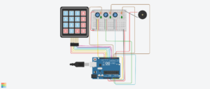
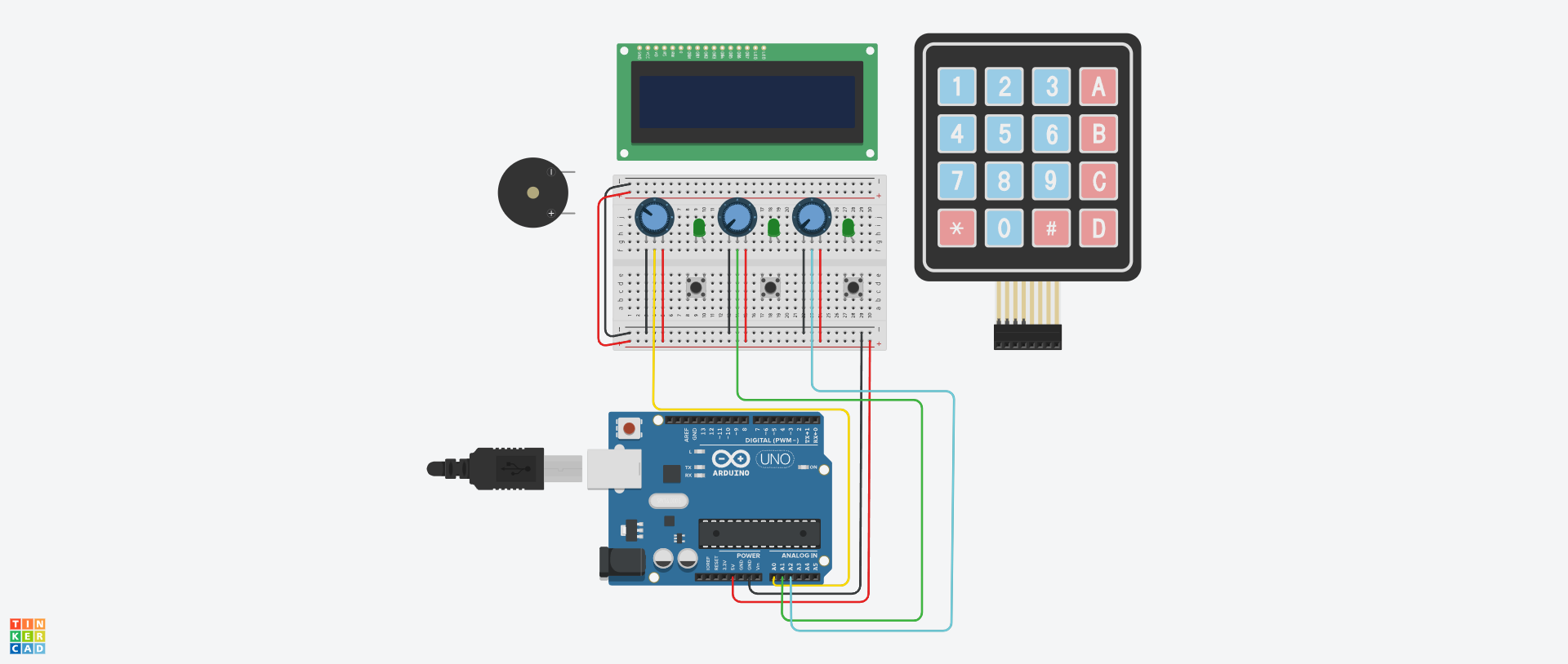
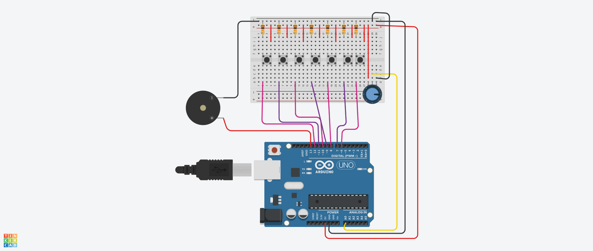
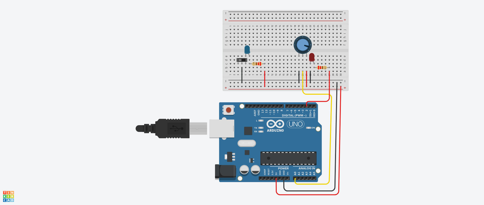
Link to the Tinkercad!

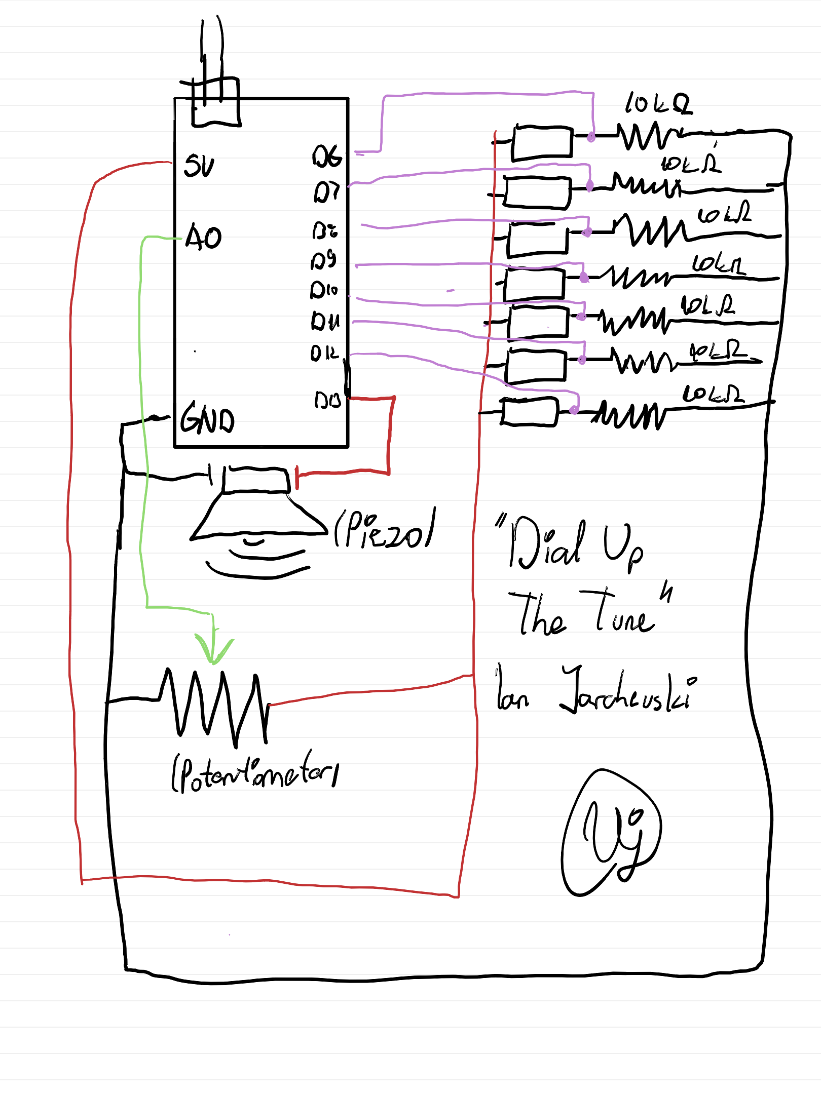
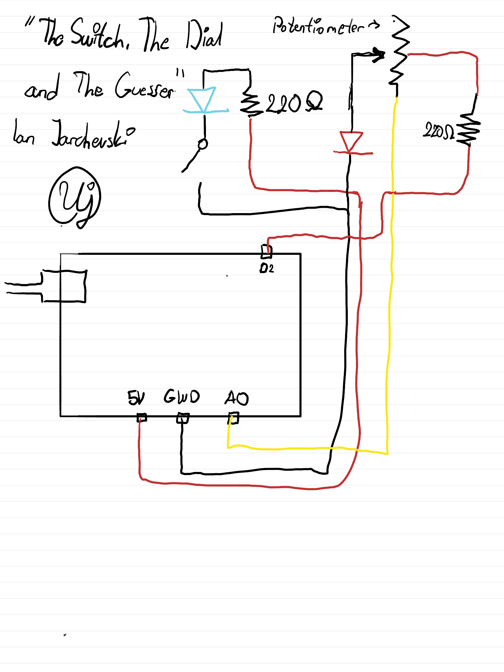
Hand Drawn Schematic:

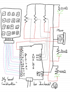
How does the Project work:

For the beginning of the code, we need to create our own custom Digital Keypad, using the Keypad.h library. For this section a special mention and credits goes to Domingo Martinez, for explaining the code and helping me understand how to use the library. Using the keypad library, we can make a 2D array where we can define each key of the keypad. And then we can use the Keypad function to create our own keypad based on the number of columns, rows and also the aforementioned 2D array.

//Adding in the relevant library for the Keypad
#include <Keypad.h>

//Defining the number of Rows and Columns for our Keypad
//Credit to Domingo Martinez for explaining the code for Keypads: https://youtu.be/sPhcOm3FdOQ
const byte ROWS = 4;   
const byte COLS = 4;   

//Creating a 2D Array for our Keypad as that's how it is structured
char hexaKeys[ROWS][COLS] = {  
  {'1','2','3','A'},  
  {'4','5','6','B'},  
  {'7','8','9','C'},  
  {'*','0','#','D'}  
};  

//Here we're saying to which pins the Keypad is connected to
byte rowPins[ROWS] = {13,12,11,10}; 
byte colPins[COLS] = {9,8,7,6};     

//Creating our own custom Keypad Map
Keypad customKeypad = Keypad(makeKeymap(hexaKeys), rowPins, colPins, ROWS, COLS);

Then we need to define the pins which we’re using for the LEDs, Piezo and the Dials. I’ve discovered you can define multiple of them in a list so I went with that approach. Also I took the liberty of creating our secret code here, being the target numbers, and also the last dial values. These numbers will be updated constantly as the user twists the dials and saves them so that the program can later use them.

//Here we can define some constants for each of our connected pins
const int dials[3] = {A0, A1, A2};
const int leds[3] = {5, 4, 3};   
const int piezo = 2;

//This will be the secret code the player needs to get
const int targetNumbers[3] = {4, 7, 2}; 

//This is a list which will update based on the values that the user gets from twisitng the dials
int lastDialValues[3]   = {0, 0, 0}; 
String enteredCode = "";

Created a small function for the Piezo, as we need to dynamically update its frequency, duration and tone, for our different sounds.

//A simple function just to define the sound for the Piezo
void tonePiezo(int freq, int duration) {
  tone(piezo, freq);
  delay(duration);
  noTone(piezo);
}

Within the Setup function, I’ve defined the serial communication, and to constantly loop in order to check the output for the LEDs and the Piezo. Also wrote a little starting message for the player in the serial monitor and kinda gives off a notification to the user that the game has started.

//Our main setup function, starting off with the serial communication
void setup() {  
  Serial.begin(9600);
  
  //A for loop which checks for each LED its output as we want to constantly update
  for (int i = 0; i < 3; i++) {
    pinMode(leds[i], OUTPUT);
  }
  pinMode(piezo, OUTPUT);
  
  //Just prints a text saying the user can start to crack the code
  Serial.println("Unlock the Code!! Twist dials to find the code.");
}

Now, we get our handy loop function. In the first part of it, I’ve created a big for loop as I want it constantly check each of the three potentiometers and see their values update. Firstly, we read the Dials’ values, then we create mapped values for each dial, using the map function. This will simply take the values of the dials, and turn them into numbers from 1 to 9, so they can be used for our keypad later. As the user twists the dial, the code checks the current mapped dial value with the previous one and updates the serial monitor with some text accordingly. This is so the user is aware what the current value of the dial is. The finally, if the mapped dial value is the same as one of the target number values, or our code, then the LED will flash, indicating to the user that they’ve gotten it correct.

//Here is where the meat of it will happen,
void loop() {  
  //Using a for loop to check for all three Potentiometers
  for (int i = 0; i < 3; i++) {
    
    //We read each potentiometer and get its value
    analogRead(dials[i]); 
    delay(5);
    int dialValue = analogRead(dials[i]);
    
    //Then we map its value using the map function
    int dialMap = map(dialValue, 0, 1023, 1, 9);
    
    //Now for each Dial, we just check if its the same as the previous value and update it with the current value
    if (dialMap != lastDialValues[i]) {
      Serial.print("Dial ");
      Serial.print(i + 1);
      Serial.print(" is now at: ");
      Serial.println(dialMap);
      lastDialValues[i] = dialMap; 
    }
    //If the value that we are on the potentiometer is the same as the value of the secret code, then the LED turns on
    if (dialMap == targetNumbers[i]) {
      digitalWrite(leds[i], HIGH);
    } else {
      digitalWrite(leds[i], LOW);
    }
  }

Now the second part of the loop function is purely dedicated to the keypad. We take our custom keypad we built above and use it for various different things. Firstly we need to give feedback to the user that they’ve pressed a button on the keypad, which is done by virtue of the first if statement. Then we add that pressed key to our string, which is used for a few things in order to check if the played got the code or not. Firstly it checks for its length, which must be three for three dials. Then we check if the string is the same as the target numbers of our secret code. If the player got the right code, we output a victory message with a happy sound effect, if not, then a error message with a buzzing sound to indicate the player is wrong.

  //From the custom keypad we make a character from the key pressed, so it will displayed
char customKey = customKeypad.getKey();

//A simple if statement that prints out the key for the user, and also uses for the ente
if (customKey) {  
  Serial.print("Key Pressed: ");
  Serial.println(customKey);
  
  //This adds the character that came from the keypad to the string
  enteredCode += customKey; 
  
  //This is just a short sound from the Piezo which is meant to serve as like feedback for the user
  tonePiezo(500, 50); 
  
  //Checks if the code is 3 characters
  if (enteredCode.length() == 3) {
    //And here we check if the secret code is the same as what the user entered
    String secretCode = String(targetNumbers[0]) + String(targetNumbers[1]) + String(targetNumbers[2]);

    //Checks if the entered code is correct or not
    if (enteredCode == secretCode) {
      Serial.println("You have guessed the combination! You win!");
      playVictorySound();
    } else {
      Serial.println("That's wrong! Try again.");
      tonePiezo(200, 500); 
    }
    //Resets the player inputted code so they can try again
    enteredCode = ""; 
  }
}

This final part is our victory sound function. I’ve used Google Gemini for this part as I had no knowledge at all of how to create it. But it was useful to understand as the way it’s done is with a list that plays each sound frequency in order, with a bit of a delay between each sound so that the sounds can be propely heard.

//Plays a happy congratulatory sound
//Used Google Gemini to figure out the melody as I didn't understand how to make a melody 
void playVictorySound() {
  int melody[] = {262, 330, 392, 523}; 
  int duration = 150;
  
  //A for loop that goes through all the notes and plays them
  for (int i = 0; i < 4; i++) {
    tonePiezo(melody[i], duration);
    delay(50); 
  }
}

Parts that I’m quite proud of:

Honestly I think the part I’m most proud of was playing around with the keypad. I didn’t have any understanding intially as when I placed the keypad in, I actually I thought it would work automatically. But after watching that video that explained it I saw that you actually have to define a full on custom keypad for your own project. Also getting to know the map function was actually something I’m proud of to know now. In one of my previous projects, I’ve used the potentiometer but I needed to fiddle around with it in the code as it had a bit of noise. But understanding this, it really helped to have a specific concrete value for each part of the potentiometer and worked perfectly in the sense of making a keypad work functionally, with not much deviation.

Areas of Future Improvements:

I think probably the biggest area of improvement is implementing it in a p5js sketch so that it can look visually appealing. Of course the limitation in Tinkercad was definitely a factor but I think I could definitely build this and make a sketch in p5js so that the player can have a visual experience with it. Another approach I was going for initally was with an LCD panel, but I had a few issues in understanding the LCD panel on its own, and also I didn’t have enough pins on my Arduino so I can add it in. Definitely one possible way to improve it as while the serial monitor does do it justice, this would be a much more visually appealing way to go about it.

Reflecting on the Final Project:

I’m very pleased that the entire project in the end worked overall correctly and all parts that I’ve put worked synchronously. And I think getting rid of the buttons actually made more sense as there is an element of discovery for the player and I think giving a button to confirm it kinda ruins the magic of figuring out what the dial and subsequent LED lighting means. I’m quite gutted that I couldn’t implement the LCD panel into it due to issues I’ve had with it. If I had extra time, I could probably figure out some sort of way to implement it with some sort additional pins to the Arduino and get it working, but time is of the essence at the moment.

But this project has really taught me how escape rooms kind of balance an equilibrium of interactivity with the player, but also not being as very obvious and letting the player discover parts on their own. Even looking back at the puzzles I’ve done in escape rooms, I can understand clearly why the main aim is discovery of the puzzles and to have an interactive design so it sparks the curiousity for the player. For this project’s user testing, I believe I’ve gotten that approach, as my tester figured out some of the components. They were able to discover their functions and with a little curiousity, were able to figure out what was needed to be done to solve the puzzle.

Thoughts overall for this course:

While this section isn’t needed I thought I’d give a bit of a paragraph of thought for this introductory course. Going into it I had no idea what I’m getting myself into as I didn’t understand what Interactive Media represented. But I think the course really captured that idea of how with a little code, creativity and interacting with different tools, we can craft some fun experiences for anyone to enjoy. The readings as well gave me a very nice and different way of thinking when it comes to how we design and interact with various different products. Genuinely I really enjoyed this course and I want to extend a heartfelt thanks to Prof Mang for his support and constant love for getting us to become curious thinkers and interactive designers. Even with the course moving remotely, I think genuinely appreciate having supplementary options to still follow along and be a part of the course. I can only hope to take more Interactive Media courses in the future!

Signing off for Intro to IM, Spring 2026 with Prof Mang, I wish all of you an amazing summer break, and make sure to take care of yourselves, keep being curious and make sure to stay awesome always!

Ian Jarchevski

Full source Code:

//My Secret Combination
//Ian Jarchevski 04.05.2026
//Intro to IM, Final Project

//Adding in the relevant library for the Keypad
#include <Keypad.h>

//Defining the number of Rows and Columns for our Keypad
//Credit to Domingo Martinez for explaining the code for Keypads: https://youtu.be/sPhcOm3FdOQ
const byte ROWS = 4;   
const byte COLS = 4;   

//Creating a 2D Array for our Keypad as that's how it is structured
char hexaKeys[ROWS][COLS] = {  
  {'1','2','3','A'},  
  {'4','5','6','B'},  
  {'7','8','9','C'},  
  {'*','0','#','D'}  
};  

//Here we're saying to which pins the Keypad is connected to
byte rowPins[ROWS] = {13,12,11,10}; 
byte colPins[COLS] = {9,8,7,6};     

//Creating our own custom Keypad Map
Keypad customKeypad = Keypad(makeKeymap(hexaKeys), rowPins, colPins, ROWS, COLS);  

//Here we can define some constants for each of our connected pins
const int dials[3] = {A0, A1, A2};
const int leds[3] = {5, 4, 3};   
const int piezo = 2;

//This will be the secret code the player needs to get
const int targetNumbers[3] = {4, 7, 2}; 

//This is a list which will update based on the values that the user gets from twisitng the dials
int lastDialValues[3]   = {0, 0, 0}; 
String enteredCode = "";

//A simple function just to define the sound for the Piezo
void tonePiezo(int freq, int duration) {
  tone(piezo, freq);
  delay(duration);
  noTone(piezo);
}

//Our main setup function, starting off with the serial communication
void setup() {  
  Serial.begin(9600);
  
  //A for loop which checks for each LED its output as we want to constantly update
  for (int i = 0; i < 3; i++) {
    pinMode(leds[i], OUTPUT);
  }
  pinMode(piezo, OUTPUT);
  
  //Just prints a text saying the user can start to crack the code
  Serial.println("Unlock the Code!! Twist dials to find the code.");
}  

//Here is where the meat of it will happen,
void loop() {  
  //Using a for loop to check for all three Potentiometers
  for (int i = 0; i < 3; i++) {
    
    //We read each potentiometer and get its value
    analogRead(dials[i]); 
    delay(5);
    int dialValue = analogRead(dials[i]);
    
    //Then we map its value using the map function
    int dialMap = map(dialValue, 0, 1023, 1, 9);
    
    //Now for each Dial, we just check if its the same as the previous value and update it with the current value
    if (dialMap != lastDialValues[i]) {
      Serial.print("Dial ");
      Serial.print(i + 1);
      Serial.print(" is now at: ");
      Serial.println(dialMap);
      lastDialValues[i] = dialMap; 
    }
    //If the value that we are on the potentiometer is the same as the value of the secret code, then the LED turns on
    if (dialMap == targetNumbers[i]) {
      digitalWrite(leds[i], HIGH);
    } else {
      digitalWrite(leds[i], LOW);
    }
  }
    //From the custom keypad we make a character from the key pressed, so it will displayed
  char customKey = customKeypad.getKey();
  
  //A simple if statement that prints out the key for the user, and also uses for the ente
  if (customKey) {  
    Serial.print("Key Pressed: ");
    Serial.println(customKey);
    
    //This adds the character that came from the keypad to the string
    enteredCode += customKey; 
    
    //This is just a short sound from the Piezo which is meant to serve as like feedback for the user
    tonePiezo(500, 50); 
    
    //Checks if the code is 3 characters
    if (enteredCode.length() == 3) {
      //And here we check if the secret code is the same as what the user entered
      String secretCode = String(targetNumbers[0]) + String(targetNumbers[1]) + String(targetNumbers[2]);

      //Checks if the entered code is correct or not
      if (enteredCode == secretCode) {
        Serial.println("You have guessed the combination! You win!");
        playVictorySound();
      } else {
        Serial.println("That's wrong! Try again.");
        tonePiezo(200, 500); 
      }
      //Resets the player inputted code so they can try again
      enteredCode = ""; 
    }
  }
  
  delay(10); 
}
//Plays a happy congratulatory sound
//Used Google Gemini to figure out the melody as I didn't understand how to make a melody 
void playVictorySound() {
  int melody[] = {262, 330, 392, 523}; 
  int duration = 150;
  
  //A for loop that goes through all the notes and plays them
  for (int i = 0; i < 4; i++) {
    tonePiezo(melody[i], duration);
    delay(50); 
  }
}

for scrolling all the way down, here’s a cat spinning on a record player 😀


Final Project User Testing

Context beforehand from my side:

For this IM Project, as I wanted to emulate the vibe of an Escape Room I deliberately didn’t make it as obvious what was supposed to be done. When you try to solve a puzzle, obviously you’re not supposed to spoonfeed the answer so I kept it kind of vague as to what was needed to be done. For my user testing, I asked my sister to try it out and see how she felt about it. But what I also should mention is that, she didn’t have really any knowledge of what Tinkercad is and its various components, so she went in completely blind.

Video of the User Testing (My sister):

Feedback from The User Testing:

In the end, she was able to figure it out on her own. From her feedback to me, she mentioned that she didn’t understand what each component meant. She understood the keypad and from prior knowledge, knew she needed to enter a code, however she did not know what the LED was or what its function was. She did in fact understood that she could twist and turn the potentiometer, but after she played around with them a little bit.

I think the experience overall is working well. The connections between components worked out and all of the components reacted on time. In terms of any imporvements, if I’m honest I think you could definitely add something that’s much more visually appealing like an LCD screen, however I faced issues with it and also didn’t understand how to connect all of it to the Arduino Uno so I omitted it in place of the serial monitor. And another thing, I think if there were more components added, then the experience wouldn’t be as mysterious for it’s own little puzzle to solve.

From parts I needed to explain, it was mostly grounded in telling her what each component was as she did not have any idea what they were. For any new user that might not be well versed in Tinkercad, that would definitely be a common problem. But I think the best way to mitigate this, is to simply have speech bubbles or a list of instructions (most likely in the description of the Tinkercad Project), explaining the main goal and the options the user can do to reach it. In this case of this, the end goal would be to figure out the code, and the user will be told what each component does and that they’re able to twist the dial and enter a code on the keypad.

Final Project Proposal: Unlocking the Combination (Working Title)

Concept:

Something I adore doing for fun is solving escape rooms with friends. While my escape/loss ratio is good enough😉, I was inspired a lot by the locks I see in escape rooms. My favorite part of the escape rooms is when you solve the puzzles and go to the next room by unlocking the lock. Usually you find a string of numbers from a different puzzle and then twist the lock to unlock it. But I wanted to flip the concept, and try by twisting the dials, to find the combination and enter it in to “escape”. So that’s how my idea came about pretty much haha.

Implementation:


The project will be completely done in Tinkercad and will utilize a few old things that we’ve seen on class but also a few new things I wanted to try out.

The way how the game would work is, each Potentiometer will act as a lock you can twist around (from this point, I’ll refer to the Potentiometers as ‘locks’).

Each lock will have a value you have to get. Now on the LCD Display I’ll have the current value that the user is twisting displayed. Then once the user twists to the right value, the Piezo will make a beep. But for the value to be correct and locked in, the user needs to twist it, listen to the sound and press the button. If the value is correct, then the LED will light up and that same value will be displayed on the screen.

From what I’ve researched, the Potentiometer can have values from 0 to 1023. But on Tinkercad, there’s an array of values that can be inputted only with mouse input.

Those values are: 0, 20, 41, 61, 82, 102, 123, 143, 164, 184, 205, 225 and so on…

Each lock will have a different value from this array of integers. When the correct value is guessed (by virtue of the LED lighting up), it will be displayed on screen. Most likely I’d do something like:

Lock 1: *the value of Lock 1*, Lock 2: *the value of Lock 2* and Lock 3: *the value of Lock 3*

After all three values have been guessed, then the user will input them on the keypad. When all three values have been entered, then a victory sound will be played by the Piezo.

Challenging parts to the Project:

I would say the most challenging part of the project is definitely understanding how to use the LCD screen and also the Keypad. I’ve not tested or played with them before but I can mitigate this by looking up the reference sheet for each Arduino part. Alongside this, I can use videos that explain these parts so I can understand how they work, but mostly so I can see how to code for them is written.

I think overall this will be a fun project to go with and experiment with these new parts in Tinkercad. Hopefully something interesting as like a minigame can come off from it.

Reading Reflection Week 12: Reinventing our Hearing and Seeing of Society

Reading through Graham Pullin, he makes some interesting arguments of how our world can actually enhance and create identity even in our disabilities we have. I think the best case made is with our glasses. It’s something I see a lot in many of my family members who require glasses to see better. Some don’t really say anything about them, while others ask around if or how the glasses they’re wearing makes them look like. But if I’m honest, I think glasses actually can very much enhance the stylistic choices of a person’s clothes. You could have say glasses that match your outfit, or highlight your personality. Even though I personally have never really judged (I mean why would you yk) for wearing glasses, I really like when I see some people just kinda go all out and choose a pair that makes them stand out, instead of hiding them like the medical world would like.

Another interesting thing is the hearing aids. Recently my grandfather actually started wearing them as he had trouble hearing and honestly I’ve not noticed them at all. I believe the main fact is that they’re flush in his ears and they’re a bodily sort of skin color to blend in with his ears. And if I’m honest, even reading the points the books makes are partially outdated as the book itself was published in 2009. Now we live in a world where everyone wears earbuds or some sort of earphones, most likely wireless as well. It mostly helps us with our listening needs of music, or podcasts and you could see them everywhere. And since we’ve normalized their use, now even some have features that can act just like hearing aids. Again, this helps a lot in making earbuds acceptable for everyone to wear. In short, now that everyone is wearing a “hearing aid” we can definitely build on making our world much more connected.

Both products at one point were stigmatized. Now they’re normalized. This practice is exactly how we can achieve a better world. Not just by reinventing meaning, but creating a design choice. Narrative does a lot in influencing public perception of a given stigma or bias. And honestly, kudos to all that are designing a more acceptable world for all to take part in, this is what we need more of. Small achievements like this, really can amount to big changes.

Reading Reflection Week 11: The Touchy Touchscreen

Bret Victor makes a really good point about the so called “Pictures under glass” concept of technology. I mean, as a bit of a fun fact, in my elementary school, our books were so in need of an update that the latest technology the textbooks about computer science, mention touchscreens as the latest technology. It’s quite laughable thinking about it. But I do have to agree, in a generation and era where we’re living a touchscreen oriented life, the magic does get lost along the way.

But thing is I think right now we have at least one example of trying to make technology adapt to fit our human body, being the reMarkable paper tablet. Initially when I was looking to buy some new technology I had this one goal in mind; that it can have a touchscreen for me to draw and write on. I primarly was looking at laptops that had touchscreens when I was introduced to the reMarkable. Now I thought, I mean its nothing special when it came to what it is and what it lacked as opposed to a conventional laptop. But after testing it out, it was astounding. It felt so natural to write on it, like I was writing in a notebook. I didn’t get that artifical feel that iPads give me and genuienly is what sold me on buying the reMarkable in the end.

At some point, we do have to ask ourselves, at what point is our life simulated by screen or whether our reality is literally a headset we can’t take off? (obviously I’m joking but it is getting quite dystopian no?)

Assignment 11: Dial up the Tune

“It’s a pity to shoot the pianist when the piano is out of tune.” – Rene Coty

Concept:

Soo, when it comes to instruments, I thought right, let’s make a piano. Now due to the limitations from the Arduino Breadboard, I couldn’t make it so all of it the frequencies are in tune, whether they’re lower or higher. So I needed to think of a way how to make it so all of the frequencies could be represented on the project. That’s where our lovely, potentiometer comes into play.

Check the Tinkercad out here!

Sketch:

Digital Circuit:

How it’s made:

Now for the design, I went with having the buttons in a line with each of them being connected to the digital input of the Arduino Uno. After adding to each a resistor, alongside a connection to the power, they were ready to go. Then we have a Piezo that is connected to the side and acts as our output for sound, or specifically frequencies.

But the special thing is our so called dial, represented by the Potentiometer. He is connected as an analog input and will serve the user as while it is rotated, the frequency will be increased or decreased. I will be honest, I actually had an issue intially with the Piezo constantly playing sound, but I figuered it out later after seeing that the resistors weren’t connected properly (always good to check this in case of any errors)

Highlighted bit of Code I’m proud of:

Now after that it was time to put it all together. The code itself is quite simple as we have read functions to take in our defined input. But what was interesting is trying to get it so each button having a different pitch. It was done by having the potentiometer’s value added on to a constant value which increases with each button. This gave way for the user to increase the pitch and then, always, it will be added to a specific constant which will give the sesne of a piano.

//potent variable is dependent on where the user slides the potentiometer
if (s1 == 1){
tone(buzzer, potent + 100, 100);
} 
else if (s2 == 1){
tone(buzzer, potent + 200, 100);
}
else if (s3 == 1){
tone(buzzer, potent + 300, 100);
} 
else if (s4 == 1){
tone(buzzer, potent + 400, 100);
} 
else if (s5 == 1){
tone(buzzer, potent + 500, 100);
} 
else if (s6 == 1){
tone(buzzer, potent + 600, 100);
} 
else if (s7 == 1){
tone(buzzer, potent + 700, 100); 
}

Reflection

I’m happy with this design and even using the Piezo for the first time was fun. I will be honest my ears didn’t like it as much but we got through it haha. I think an extension is to make it so you could have some sort of keyboard input or even make original songs with it. I saw some interesting ideas of how by getting specific frequencies in a loop, you could make a song which I’d love to experiement with this for my final project.

Full Code:

//Declaring every button to it's assgined digital value
int tone1 = 12;
int tone2 = 11;
int tone3 = 10;
int tone4 = 9;
int tone5 = 8;
int tone6 = 7;
int tone7 = 6;

//And here declaring the Piezo at Digital 13
int buzzer = 13;

void setup ()
{
  
//Starting up the Serial Connection on Arduino
  Serial.begin(9600);
  
//Making all of the buttons take in our Input 
  pinMode(tone1,INPUT);
  pinMode(tone2,INPUT);
  pinMode(tone3,INPUT);
  pinMode(tone4,INPUT);
  pinMode(tone5,INPUT);
  pinMode(tone6,INPUT);
  pinMode(tone7,INPUT);
  
//Making the buzzer as our output  
  pinMode(buzzer,OUTPUT);
}

void loop () 
{
  
//Defining a variable which is the value of the potentiometer
  int potent = analogRead(0);
  
//Outputing the value in the console
  Serial.println(potent); 
  
//Reading a value for each pin
  int s1 = digitalRead(tone1);
  int s2 = digitalRead(tone2);
  int s3 = digitalRead(tone3);
  int s4 = digitalRead(tone4);
  int s5 = digitalRead(tone5);
  int s6 = digitalRead(tone6);
  int s7 = digitalRead(tone7);

//If else conditions where, when the button is on, it will output a sound
//potent variable is dependent on where the user slides the potentiometer
  if (s1 == 1){
  tone(buzzer, potent + 100, 100);
  } 
  	else if (s2 == 1){
  tone(buzzer, potent + 200, 100);
  }
  	else if (s3 == 1){
  tone(buzzer, potent + 300, 100);
  } 
  	else if (s4 == 1){
  tone(buzzer, potent + 400, 100);
  } 
  	else if (s5 == 1){
  tone(buzzer, potent + 500, 100);
  } 
  	else if (s6 == 1){
  tone(buzzer, potent + 600, 100);
  } 
  	else if (s7 == 1){
  tone(buzzer, potent + 700, 100); 
  } 

//Just to give a short delay between presses
  delay(10);
  
}


Assignment 10: The Switch, The Dial and The Guesser

“Turning on the light is easy if you know where the switch is” – Colin Wilson

Concept:

Finally we have reached the Arduino era of the class. So to start out, we were tasked to make a analog switch and a digital switch to turn on two LEDs in a digital and analog fashion. But as well, to add a bit of spice to it. Now being honest it took me some time to get my footing with Arduino as this is my first time using and tinkering with it. But I’ve managed to make something at least a bit fun. I’ve been fond of escape rooms and locks, and I thought, what if I make it so depending on where you twist the lock, the LED will shine.

Sketch:

Digital Circuit:

How it’s made:

In terms of designing, the Blue LED is a simple circuit, featuring a resistor set at 220 olms, and wires connecting it to the Ground and Power. The key thing added is a simple switch that the user can interact with to turn the LED on or off.

However the Red LED has instead a potentiometer. I chose it as it’s use as a dial is going to be key to solving what random value the LED is in. Basically, I have a random function that generates a random value between the lowest and highest value of the potentiometer. Then we read the current value of the potentiometer which uses the function analogRead(). And finally we use a simple if else statement to check if the value is the same, and if so the LED will shine. I’ve added a buffer just so it’s not too difficult to guess.

Highlighted bit of Code I’m proud of:

Outside of the regular struggles with making the digital design, I struggled figuring it out why the random value wasn’t truly random. It was confusing as I assumed somehow it was reading the value of the potentiometer and using that variable as a constant. But that wasn’t the case, so I was a bit dumbfounded as the result variable in the code below isn’t tied to anything.

I did a bit of googling and found out that if I use the random function then it will give me a random number. But, it will repeat everytime, practically serving as a constant, and that wasn’t helpful everytime I would start the simulation. So apparently, you are supposed to add a seed to a code to make it unique and it must be on a unconnected pin as it picks up different static which determines the randomness. Really interesting honestly, but a pain to figure that quirk out.

randomSeed(analogRead(A0));
result = random(0, 1022);

Reflection

Overall I’m pleased with my tinkering for now. I feel like just making the digital design on tinkercad was an experience in itself but also trying to find some sort of creative spin for the LEDs. I think potentially I could add more to it, but I’m fine this being a simple game and hopefully as the weeks go, we can try out different things.

Full Code:

int inputPin = 0;
int outputPin = 2;
int result = 0;

void setup(){
  
  Serial.begin(9600);
  
  randomSeed(analogRead(A0));
  result = random(0, 1022);
  
  pinMode(outputPin, OUTPUT);
  
}
  
void loop(){
 
  int potentialVal = analogRead(0);
  Serial.println(potentialVal);
  Serial.println(result);

  if (potentialVal >= result - 20 && potentialVal <= result + 20){
    digitalWrite(outputPin, HIGH);
  }
  else{
  	digitalWrite(outputPin, LOW);
  }
  
}


Reading Reflection Week 10: Reboot it and Mute it

Tom Igoe really presents some interesting messages surrounding about our own projects. Firstly, a core message of not being discouraged if an idea has “been done before”. I like a lot of his submissions that he showed off and how we require the limitations part of our projects (and also the feedback that Mang presents for us 😊). I can see this in this in light of my own work in content creation for YouTube.

Much of the time I struggle with determining an idea for a video, especially in the niche community that I’m in where most ideas have already been “made before”. But sometimes I like taking a different approach and look at an idea from a different prism. It helps me build on the ideas that the original creator has made, and of course providing credit, whilst injecting my own spin on the idea and creating a different product in the end. Our imagination isn’t a limitation, the critical thinking we don’t do is.

And his next message is around not interpreting our own work. Honestly, after visiting multiple art galleries and even being an usher for Abu Dhabi Art Exhibition 2025 for an Interactive Media artist, I can definitely agree with this.

For some context, I was a volunteer for the Abu Dhabi Art Exhibition 2025, held at the Manarat Al Saadiyat Gallery, with my task being to usher people to an exhibition hosted by reImagined Art. Now, even though the person there only gave me the responsibility to usher people, I also decided to talk to the guests about the artworks and give them a bit of background.

The artworks mainly revolved around the Ethirium blockchain and represented it in different forms (I’ll upload some pictures below 😉). And as guests were coming in, they were astounded by some artworks. I didn’t want to intrude into their experience of the artworks and wanted to give them time to sink in.

Later, some would come up to me and ask for me to explain to them what the artwork meant. I gave them a decent rundown but also was a bit ambivilous as most aren’t tech savy to know about blockchain (I mean they hear crypto or bitcoin and everyone goes “ahh”). Still I can say that they definitely felt astounded as to how something like a ledger for records can be art.

And I think with this, I let more so the guests the agency to interpret the work, rather than letting me being the post it note describing it in detail. So definitely we should be a bit ambivilous in what we say about our work and let others experience it. That in of itself is the crux of imagination, seeing our world from a different prism of thought.

Reading Reflection Week 8: Aesthetics, Auto-Saving and Appeal

Norman makes a really interesting argument that I see throughout daily life of how a positive mood is really a partnership of the aesthetics vis a vis the usability of the product. I mean, whenever I upgrade my own technology, I see a lot of benefits from the upgrade and with that, I can see how it does influence my thinking. As an example, with my previous Xiaomi phone, I found a lot of workarounds for say installing apps that aren’t available in my region or even some hidden features that made my use of the device much more intuitive.

However I’d like to extend his argument by saying that brand loyalty does also play a factor in our thinking. I upgraded to a Google Pixel phone and I think I mostly got sold on it, because of the abudance of features and the whole Google brand. I mean, I’m enjoying the phone don’t get me wrong, but when I encunter a minor issue, it doesn’t really appaul me, more so I’m patient but particularly because I strongly side with Google as the brand value of it. So there’s definitely an argument to made there that if you are loyal and trust a brand, then your thinking is based off it.

With regards to Hamilton, I think it’s really interesting that there was a time where people thought that humans didn’t need support or help because NASA just assumed that astronauts are equipped with a higher degree of knowledge. Nowadays, we constantly make mistakes (I mean even writing this I almost forgot to save my work 😭) and I couldn’t imagine living with technology without error checks. And I think some people do get offended or at least frustrated with error check screens as they’re so constant and everywhere. But man, imagine if we didn’t have them. What kind of society would we live in?

Midterm Project: A Handful of Color

Project:

Concept:

The main concept behind this project was my 3rd production assignment “Colorful Concoction“. Ever since that asssignment I’ve wanted to build up on it and create something generative to the user and interactive in the same sense. So when I found out that we had access to tools such as hand tracking and face tracking, I knew I wanted to go deeper into creating something that would truly give a fun feeling to the user.

I decided to create a simple project where the user could generate balls of different color and with the user’s hand, they are able to decide the size of the given ball. So if the user chooses to make a screen filled with tiny balls, they are able to. Or if they want larger ones they can as well. It gives that sense of variety for the user. And then they are able to interact with the balls using their own hands by flicking them around and pushing them. This was the main highlight of what I wanted to do to make it truly fun for the user.

So how does it work and what am I proud of:

The program starts with an instructions screen I whipped up in Canva, waiting for the user to click to start the actual program. Going from my own game that I’ve made for a different course, it was done using different states for when the program should be starting, and when it should be played (which is why they’re named game state).

function draw() {
  //Different state for Start, to show the instructions screen
  if (gameState === "START") {
    //Displays the instruction screen
    image(instructionsImg, 0, 0, width, height);
    
  } 
//Starts the actual program
  else if (gameState === "PLAY") {

    background(0);

Now in order for the user to actually create the ball, they must firstly allow camera access and then present their hand to the camera so it can track their position of their thumb and index finger. The tracking was done simply with ml5.js’ hand tracking library which was of course the main part of the whole project. Now in terms of the size of the ball, that was simply done with seeing the distance between the points of the thumb and index finger, and from there we can generate a simple circle. Also to note all of the balls were added to an array so that it can be dynamically updated when needed.

let finger = hand.index_finger_tip;
        let thumb = hand.thumb_tip;

        //Finds the midpoint between the thumb and index finger
        currentX = (finger.x + thumb.x) / 2;
        currentY = (finger.y + thumb.y) / 2;
        
        //Based off the distance, it determines the size of the ball
        currentPinch = dist(finger.x, finger.y, thumb.x, thumb.y);

        //This makes a new random color for the cursor on screen, or in this case the ball
        cursorColor = color(random(255), random(255), random(255), 200);
        
        //Creating the random colored ball
        fill(cursorColor); 
        stroke(255);
        strokeWeight(2);
        circle(currentX, currentY, currentPinch);

Problems and how I solved them:

The main part of the program was also the main problem that I faced. Getting the hands to be displayed on screen while also giving the balls a notion that they should think of the hands as a wall was a bit tricky to write. Not to mention that doing hand tracking with a camera isn’t as smooth as it could be so it took a good amount of time before I got it working.

Firstly, using the ml5js reference, all of the joints of the hand were marked with numbers. Using this, I made an array where all of the joints can be loaded and I could then dynamically add lines to them and dots to signify the joints of the hand. handPose keypoints diagram

This was done using a for loop that constantly loads the lines and joints depending on where the hand is, so that it is actively updating where the hand is on the screen instead of just, having a static image. I used Google Gemini to help me out with this part as I struggled with how I would conenct the hands using lines and create the skeleton.

//This draws the lines for the skeleton of the hand
for (let i = 0; i < connections.length; i++) {
  let pointBase = hand.keypoints[connections[i][0]];
  let pointEnd = hand.keypoints[connections[i][1]];
  line(pointBase.x, pointBase.y, pointEnd.x, pointEnd.y);
}

//This draws the joins as white dots
fill(255);
noStroke();
for (let i = 0; i < hand.keypoints.length; i++) {
  circle(hand.keypoints[i].x, hand.keypoints[i].y, 10);
}

And after that it was simple as to just adding vectors to the balls and having them repeal off the canvas’ wall and also off the hand as well. Finally after a good while, I managed to get it to work. Now your mileage may vary, as some camera’s capture it better than other (I myself was stuck with an older, bit blurry camera).

Areas of Improvement:

Most of all I think the main area of improvement for me is just probably to add more customization should I want to. I was debating on having some way for the user to change color, but time constraints sort of hampered that notion. I was thinking even this by itself can be enough as adding too much can drown out the simple nature of the project.

I think another area is making it seemless for the user to interact with the program fully with their hands. I tried but I wasn’t getting the results I desired and ultimately I decided just to stick with keyboard inputs for most things which is unfortunate. Possibly it could be a nice idea to have it so the other hand can be clamped and the ball could spawn or somehow find a gesture with a hand that could change modes. But overall I’m happy with how it turned out in the end.