Final Project Documentation

Concept

I was thinking long and hard about the final project that would be a great finale to all of the things we have learned during the semester. I have decided I want to make a robot. Robot is a broad term and I had to decide the purpose of mine, and since I wanted to create something that is innovative, fun and creative I decided to make a maze solving robot. The initial plans were to make the robot go through the maze on its own and have the user just set up the maze, but we will get to why it didn’t work out like that later. Instead of the robot solving the maze on its own, now its the user who is in control and trying to go through it “blind”, precisely using the ultrasonic sensors as guides. The user that controls the robot does not see the maze and is solving it based just on the sensors, while their friend rearranges the maze between sessions in order to make the game fun and interesting throughout the session.

Video of user interaction with the project
Arduino code
const int AIN1 = 13;
const int AIN2 = 12;
const int PWMA = 11;

const int PWMB = 10;
const int BIN2 = 9;
const int BIN1 = 8;

const int trigPinFront = 6;
const int echoPinFront = 5;

const int trigPinLeft = A0;
const int echoPinLeft = 2;

const int trigPinRight = 4;
const int echoPinRight = 3;

unsigned long lastEchoTime = 0;
const unsigned long echoInterval = 300;

void setup() {
  Serial.begin(9600);

  pinMode(AIN1, OUTPUT); 
  pinMode(AIN2, OUTPUT); 
  pinMode(PWMA, OUTPUT);
  pinMode(BIN1, OUTPUT); 
  pinMode(BIN2, OUTPUT); 
  pinMode(PWMB, OUTPUT);
  pinMode(trigPinFront, OUTPUT); 
  pinMode(echoPinFront, INPUT);
  pinMode(trigPinLeft, OUTPUT); 
  pinMode(echoPinLeft, INPUT);
  pinMode(trigPinRight, OUTPUT); 
  pinMode(echoPinRight, INPUT);

  Serial.println("READY");
}

void loop() {
  if (Serial.available()) {
    char command = Serial.read();

    //Resppond to command to move the robot
    switch (command) {
      case 'F':
        leftMotor(50); rightMotor(-50);
        delay(1000);
        leftMotor(0); rightMotor(0);
        break;
      case 'B':
        leftMotor(-50); rightMotor(50);
        delay(1000);
        leftMotor(0); rightMotor(0);
        break;
      case 'L':
        leftMotor(200); rightMotor(200);
        delay(300);
        leftMotor(200); rightMotor(200);
        delay(300);
        leftMotor(0); rightMotor(0);
        break;
      case 'R':
        leftMotor(-200); rightMotor(-200);
        delay(300);
        leftMotor(-200); rightMotor(-200);
        delay(300);
        leftMotor(0); rightMotor(0);
        break;
      case 'S':
        leftMotor(0); rightMotor(0);
        break;
    }
  }

  //Send distance data to the serial
  unsigned long currentTime = millis();
  if (currentTime - lastEchoTime > echoInterval) {
    float front = getDistance(trigPinFront, echoPinFront);
    float left = getDistance(trigPinLeft, echoPinLeft);
    float right = getDistance(trigPinRight, echoPinRight);

    Serial.print("ECHO,F,"); Serial.println(front);
    Serial.print("ECHO,L,"); Serial.println(left);
    Serial.print("ECHO,R,"); Serial.println(right);

    lastEchoTime = currentTime;
  }
}

//Logic for controling the movement of the right and left motor
void rightMotor(int motorSpeed) {
  if (motorSpeed > 0) {
    digitalWrite(AIN1, HIGH);
    digitalWrite(AIN2, LOW);
  } else if (motorSpeed < 0) {
    digitalWrite(AIN1, LOW);
    digitalWrite(AIN2, HIGH);
  } else {
    digitalWrite(AIN1, LOW);
    digitalWrite(AIN2, LOW);
  }
  analogWrite(PWMA, abs(motorSpeed));
}

void leftMotor(int motorSpeed) {
  if (motorSpeed > 0) {
    digitalWrite(BIN1, HIGH);
    digitalWrite(BIN2, LOW);
  } else if (motorSpeed < 0) {
    digitalWrite(BIN1, LOW);
    digitalWrite(BIN2, HIGH);
  } else {
    digitalWrite(BIN1, LOW);
    digitalWrite(BIN2, LOW);
  }
  analogWrite(PWMB, abs(motorSpeed));
}

//Logic for measuring distance
float getDistance(int trigPin, int echoPin) {
  digitalWrite(trigPin, LOW);
  delayMicroseconds(2);
  digitalWrite(trigPin, HIGH);
  delayMicroseconds(10);
  digitalWrite(trigPin, LOW);

  long duration = pulseIn(echoPin, HIGH);
  float distance = duration / 148.0;
  return distance;
}

The Arduinos main purpose is to handle motor move meant as well as use the data from the distance sensors and send them to p5. For the movement it takes data from p5 which the user enters by pressing buttons on the keyboard and translates them to motor movement which imitates the movement on screen. The data from the 3 ultrasonic sensors is picked up with the Arduino and sent to the serial in order to be picked up by p5.

The p5 code takes the echo values that the Arduino sends and uses that date to draw the “echo lines” which the user will use to “see” the maze with the walls being visible every now and then if in range. P5 is also used to take user input and send it to the Arduino which translates it to movement. It also has code that serves as main connection from the Arduino to p5.

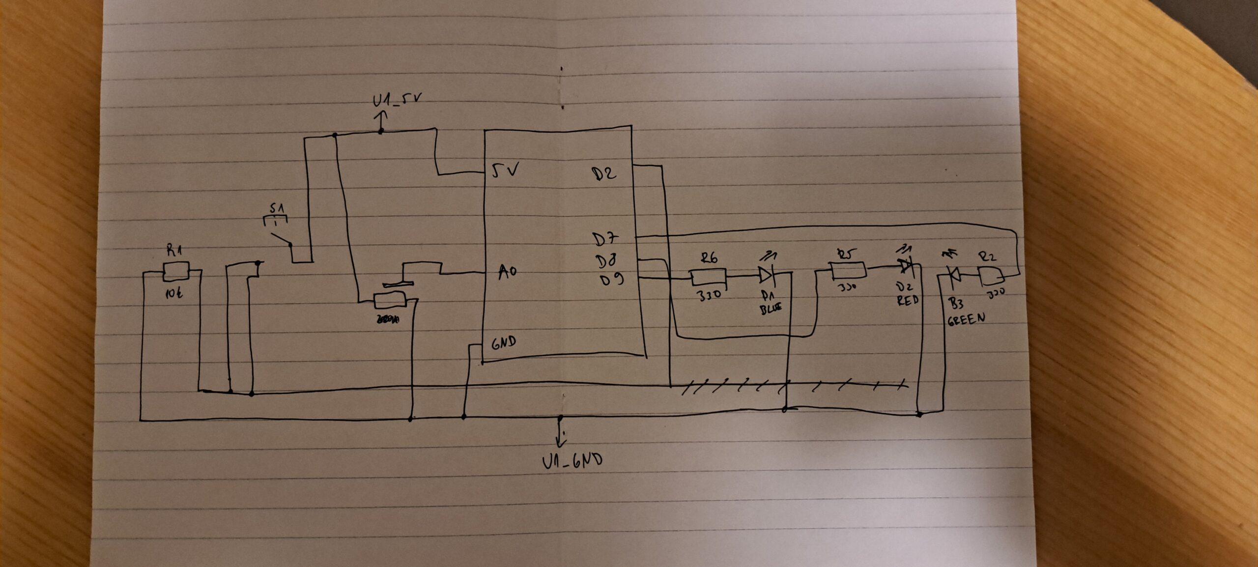
Here is the schematic of the circuit. One of the most challenging parts of this project was connecting all the wires and making sure they wouldn’t disconnect during transportation and during the showcase. I kept all the wires as far apart from each other as possible and made sure everything that could move them is nicely secured to the plate.

The making of the project

Making this project was a journey. What seemed to be a straight forward project turned out to be a 2 week long process of trial and error until I got the final result.

As I have mentioned above in the beginning the idea was to make the robot go through the maze on its own and have the user just set up the maze.

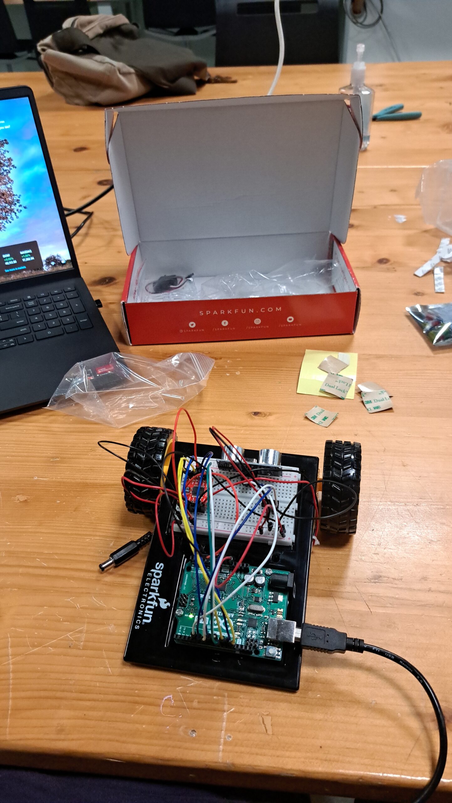
This is one of the photos of the early stages of development of the robot. As you can see it looks so much different than the final product. This was the part of the project where I was focusing on just getting the movement and some reading from the sensors.

After I managed to get the movement done with the cable attached and with sending commands through my laptop I was ready to move on to the next phase which was adding 2 more sensors and having the robot move on its own. But before I could even do that I wanted to start working on the maze. The base of them maze was 120cm wide and 180cm tall, so if I put it up it would be roughly the same size as me. I also had to make the walls of the maze which were 20cm each in order to get picked up by the sensors on the robot. I also created temporary walls that could be moved by the users to give more interactivity to the project. This turned out to be much more of a time consuming and painful process than I thought because I had to use scraps of cardboard and make sure each peace is not only 20cm tall, but also that the cut on the side of the piece is straight enough so it can stick to the other piece. After that was done, testing for the autonomous movement was ready to start.

The movement seems to be alright, but if you watched carefully in the beginning the paperclip that was used as the 3rd wheel got a bit stuck on the cardboard. At the time of the recording of this video I didn’t think that would be an issue, but damn was I wrong. After more testing something scary started happening. The paperclip wouldn’t only get stuck a bit and make the robot slow down, it would actually fly right off the robot every time it got stuck. Also other problems came up, such as the robot constantly resetting in place every time it would start without a cable attached to it and also the third sensor not reading anything. So lets go through one problem at a time.

The problem with the robot resetting was very easy to debug and fix. The main reason something like that would be happening only when the cable is not plugged would mean something with the power is not alright. At the time I was using 4 1.5V batteries to power the motors of the robot as well as the Arduino which proved to be insufficient.  The fix was to connect a 9V battery to the motors to allow the 1.5V batteries to be used just by the Arduino which fixed the problem. The next problem was the reading of the ultrasonic sensors. from all the wiring I have ran out of digital pins and had only one digital and one analog pin left for the sensor. After searching the internet I read that it should be fine since the analog pins can behave as digital, but my readings were still just 0. After talking with the professor who went through the source code of the Arduino he discovered that “Indeed there is a conversion table for pin numbers to their internal representations (bits in a port) and the table only includes the digital pins!”. The fix that the professor suggested and which ended up working is plugging the Echo pin in the analog one and the Trig in the digital. This helped me move on with the project and I would like to thank professor Shiloh one more time for saving me countless hours debugging!

Back to the movement issue. Because the paperclip kept getting stuck and flying off I had decided to remove it completely and instead use a wheel in the back which would act as support and allow the robot to move through all the bumps in the floor without a problem, or so I thought. After cutting the acrylic and getting the wheel in place I spent 2 hours trying to get the acrylic to stick to the base of the robot and in the process I superglued my finger to my phone which was not a fun experience at all! When I managed that I started the robot up and all seemed fine until I decided to try it out on the maze. Not only was the robot not detecting the walls, it was also not turning at all. After another countless hours of debugging here is what happened.

First of all the ultrasonic sensors are very unreliable which I found was the reason the robot wasn’t seeing the walls. Sometimes the reading would be 25 inches and would suddenly jump to 250inches which was impossible because it would mean the walls were too far apart. This was the main reason I decided to switch from an autonomous robot to the one that is controlled by the user. As for the movement, since the wheel was made out of rubber it created friction with the cardboard an it didn’t allow the robot to make a turn. It took me a lot of trial and error to realize the problem and come up with somewhat of the solution. I taped the the bottom up with clear duct tape which was slipping on the cardboard and allowed turning. The problem with this was the mentioned slipping, as one press of the button would make the robot go 360. I put in tape on the bottom of the cardboard which would stop that, but would also sometimes stop the turning mid way. In retrospect I would have saved myself so much trouble if I just let go of the idea of the cardboard floor!

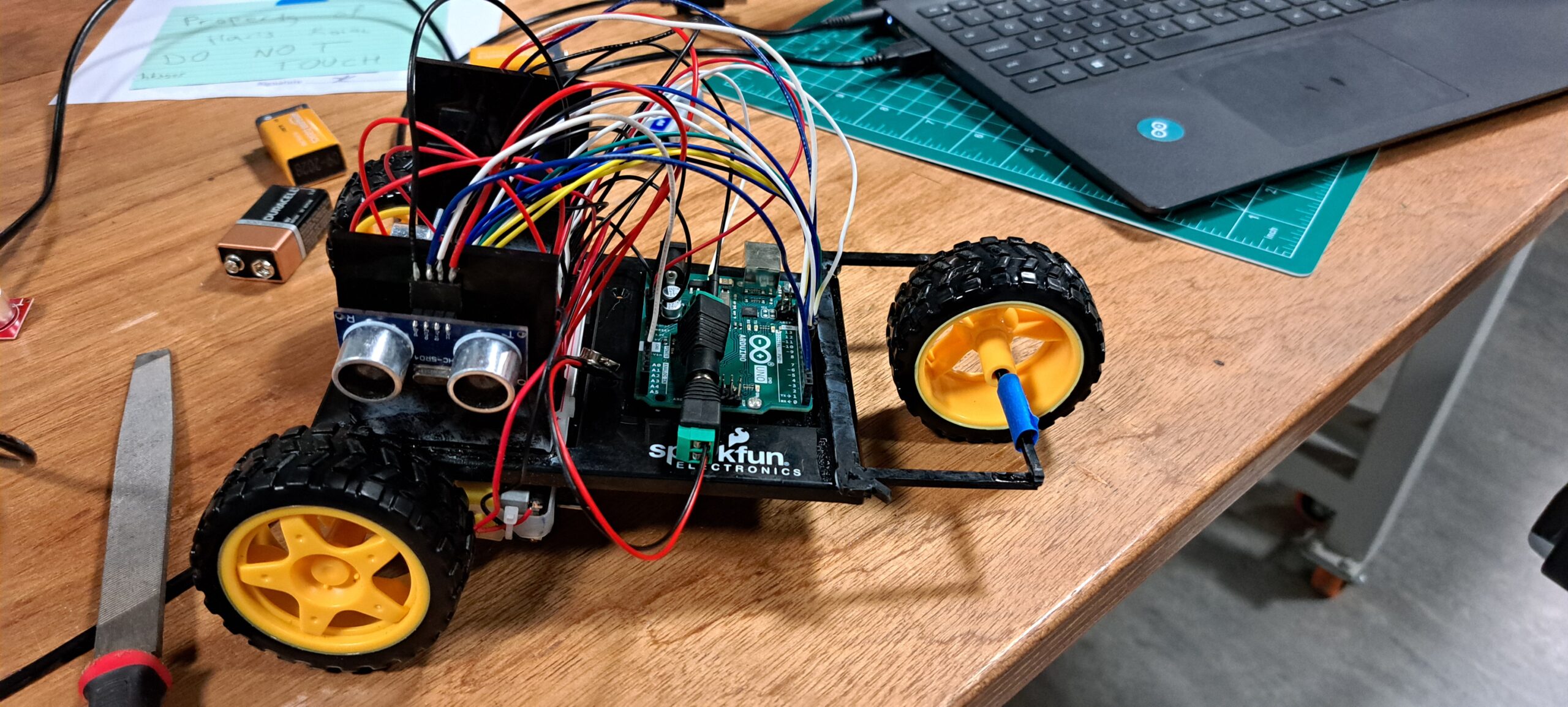
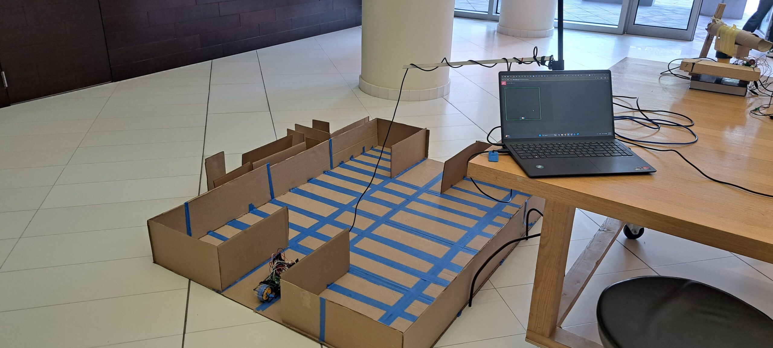
And so we come to the final design of the robot and the maze.

Areas of improvement

There are definitely some areas that could be worked on more in order to make the robot more functional. The first and most obvious one would be changing the cardboard floor with something else, perhaps something which doesn’t have bumps in it and wouldn’t create too much friction. Another thing is removing the back wheel and adding something else in its place, something that allows it to spin in place, but creates enough friction so the robot is not just spinning around in circles. I would also add an instructions page on the p5 as I have realized some users were confused on what to do when they approached the computer. Also I would try to find an alternative to the ultrasonic sensors and use something much more reliable which would allow the autonomous movement of the robot.

Things I am proud of and conclusion

I am honestly proud of the whole project. I think it is a great reflection of the things we have learned during the semester of Intro to IM and a great representation of how far we have come. When I started the course I didn’t even know how to connect wires to bake an LED light up, and here I am 14 weeks later making a robot that drives around the maze. Even though the journey to the end product was a bumpy one, I am grateful for everything I have learned in the process, every wire I had to cut and put back 20 times, all the sensors I went through to find the ones that work, all of it taught me valuable lessons and I am excited to start with new projects in the future. Thank you for reading through my journey through this class and I hope I will have a chance to write a blog again when I start my next project!

Final Project Proposal

When I was thinking about the final project my first idea was to make something innovative and playful at the same time. I decided to make a maze solving robot. The robot would solve the maze on its own, but I would make it interactive by allowing the users to set up the maze how they want.

I plan to create the maze out of cardboard to make it easy to transport and not heavy to move around and change between users. I am planning to also mark sport on the bottom to show outlines of where the boxes can be placed. The user will still be able to place the boxes however they want, but this needs to be done to insure the users don’t put the boxes too close or too far apart therefor “confusing” the robot.  To mark these outlines I am planning to simply tape some colored tape on the floor.

The robot will use a DC motor with wheels to move around and would “see” using the ultrasonic distance sensors. Currently I am looking into making the design as wireless as possible in a sense that the robot will be powered using external power like batteries and not be connected to the laptop to allow for better mobility. The batteries are a solution for the power part, but for the p5 code I will have to be connected to my laptop. I am looking into ways to make the Arduino connect to p5 using Bluetooth but if it proves to be too unreliable I will use the cable and figure out how to adjust the mobility based on that.

As for p5js I plan to make a outline of the “map” of the maze. The robot will move around and leave dots or “breadcrumbs” to show the quickest way solve the given way. I think this will give a nice UI to the whole design.

Week 11 – Reading Response

Reading Design Meets Disability made me rethink how we define good design. It is not just about solving problems efficiently, it is also about expression and identity. What I found really interesting was how the glasses were transformed from a medical device to a mainstream fashion statement. It made me wonder if other assistive devices could follow the same path? Should functionality mean sacrificing design? The reading made me realize that design should follow a broader design principle, one that serves everyone better. We shouldn’t focus just on how things work, but how they feel, how they look, and what the y say about the people using them. That is not just assistive design. That is human centered design.

Week 11 – Serial Communication

Task 1:
Make something that uses only one sensor  on Arduino and makes the ellipse in p5 move on the horizontal axis, in the middle of the screen, and nothing on arduino is controlled by p5

P5js code:

let sensorValue = 0;

function setup() {
  createCanvas(640, 480);
}

function draw() {
  background(220);

  // Map the sensor value (0–1023) to canvas width (0–640)
  let x = map(sensorValue, 0, 1023, 0, width);
  
  // Draw ellipse in center which is moved on the x axis by the potentiometer
  ellipse(x, height / 2, 50, 50);
}

function keyPressed() {
  if (key === ' ') {
    setUpSerial();
  }
}

function readSerial(data) {
  if (data != null) {
    sensorValue = int(trim(data)); 
  }
}

Arduino code:

void setup() {
  Serial.begin(9600);
}

void loop() {
  int sensorValue = analogRead(A0); //read the data from the potentiometer
  Serial.println(sensorValue);      //send it to p5
  delay(20);                        
}
Task 2:
Make something that controls the LED brightness from p5
P5js code:
function setup() {
  createCanvas(640, 480);
  background(0);
}

function draw() {
  background(0);
  
  // Map mouseX to brightness value (0–255)
  let brightness = map(mouseX, 0, width, 0, 255);
  fill(brightness);
  ellipse(mouseX, height / 2, 50, 50);

  // Send to Arduino only if serial is active
  if (serialActive) {
    writeSerial(int(brightness) + '\n');  // Send as string + newline
  }
}

function keyPressed() {
  if (key === ' ') {
    setUpSerial();
  }
}

//need to leave this empty as we are not reading anything from the arduino
function readSerial(data) {
}

Arduino code:

void setup() {
  Serial.begin(9600);
  pinMode(5, OUTPUT);
}

void loop() {
  if (Serial.available()) {
    int brightness = Serial.parseInt();  //read incoming value from p5
    if (Serial.read() == '\n') {
      brightness = constrain(brightness, 0, 255);
      analogWrite(5, brightness);        // set LED brightness
    }
  }
}
Task 3:

Take the gravity wind example (https://editor.p5js.org/aaronsherwood/sketches/I7iQrNCul) and make it so every time the ball bounces one led lights up and then turns off, and you can control the wind from one analog sensor

P5js code:

let velocity;
let gravity;
let position;
let acceleration;
let wind;
let drag = 0.99;
let mass = 50;

let sensorValue = 512; // default before Arduino sends anything
let bounced = false;

function setup() {
  createCanvas(640, 360);
  noFill();
  position = createVector(width / 2, 0);
  velocity = createVector(0, 0);
  acceleration = createVector(0, 0);
  gravity = createVector(0, 0.5 * mass);
  wind = createVector(0, 0);
}

function draw() {
  background(255);

  // Map sensorValue to wind force between -1 and 1
  let windStrength = map(sensorValue, 0, 1023, -1, 1);
  wind.x = windStrength;

  applyForce(wind);
  applyForce(gravity);

  velocity.add(acceleration);
  velocity.mult(drag);
  position.add(velocity);
  acceleration.mult(0);

  ellipse(position.x, position.y, mass, mass);

  // Bounce detection
  if (position.y > height - mass / 2) {
    velocity.y *= -0.9;
    position.y = height - mass / 2;

    if (!bounced) {
      bounced = true;
      if (serialActive) {
        writeSerial("1\n");
      }
    }
  } else {
    bounced = false;
  }
}

function applyForce(force) {
  let f = p5.Vector.div(force, mass);
  acceleration.add(f);
}

function keyPressed() {
  if (key === ' ') {
    setUpSerial();
    position.y = -mass;
    velocity.mult(0);
  }
}

function readSerial(data) {
  if (data != null) {
    sensorValue = int(trim(data));
  }
}

Arduino code:

int ledPin = 5;

void setup() {
  Serial.begin(9600);
  pinMode(ledPin, OUTPUT);
}

void loop() {
  //read potentiometer value
  int sensorValue = analogRead(A0);
  Serial.println(sensorValue);

  //if we receive "1\n" from p5, blink the LED
  if (Serial.available()) {
    int signal = Serial.parseInt();
    if (Serial.read() == '\n' && signal == 1) {
      digitalWrite(ledPin, HIGH);
      delay(100);
      digitalWrite(ledPin, LOW);
    }
  }

  delay(20);
}

Week 10 – Reading Resonse

I agree with the rant so much! At first I didn’t really think about how we unknowingly use the feel we get from our fingers to deeply understand everything around us. From the fullness of the cup to the amount of pages of the book we are holding, we constantly see the world through our hands without even knowing it. The tablets and the screens are taking that away from us. The screens do bring us so much good, and are useful in many situation, but they are taking the real world away from us. Newer generations especially are so glued to the screen so they can’t see anything real around them (I’m beginning to sound like my parents). The response to the rant was specifically infuriating to me, not because of the reply from the author, but because of the questions people were asking and the opinions they were giving. There is nothing that makes me more angry then seeing a family out for dinner and their kid staring at their iPad the whole time. The same goes for when the young kids spend their whole day laying down stuck to the screen, watching videos or playing video games. Kids should be kids, explore the world, play around without worry, not spend hours sitting and staring at the screen, there will be plenty of time for that later! I might’ve strayed away from the topic a bit, but overall I do agree that unfortunately technology is taking away our way of seeing the world.

Week 10 – Musical Instrument

Concept

We were thinking a lot about what kind of instrument we want to make and wanted to stray away from the classic, well known ones like guitar and piano and drums and we decided to recreate an instrument many haven’t probably heard of, called Otomatone.

The instrument work by the user pressing the upper longer part of the instrument in different positions and pressing the “mouth” on both sides so it opens. The instrument than creates a sound and makes it look like the character is singing.

Our design

To recreate this we decided to use light resistors as the upper part of the body. The resistors would detect when the user puts their hand over them and create a sound. But the sound wouldn’t be heard until the user pressed on the “cheeks” of the character which had force resistors to detect the force of the press.

Here is the photo of the board and the photoresistors. We also added a button which, if held, will give the sound some vibration while playing. The final design of our Otomatone instrument looks like this:

Code higlight

The code for this instrument wasn’t that complicated. The hardest part was finding the values for all the notes but we used the help of the internet for that.

// Multi-note LDR1
if (ldrVal1 < 500 && duration > 10) {
  if (totalPressure < 256) {
    activeNote = 440; // A4
  } else if (totalPressure < 512) {
    activeNote = 523; // C5
  } else if (totalPressure < 768) {
    activeNote = 659; // E5
  } else {
    activeNote = 784; // G5
  }
  Serial.print("LDR1 note: "); Serial.println(activeNote);
}

This is the code for one of the light resistors which as you can see combines the value of the resistor with the total pressure of the force sensors detected and gives us a tone based on those calculations. The code for other light resistors is similar and not too complicated to understand.

Challenges and future improvement

The biggest challenge for this project was, surprisingly, getting the buzzer inside the “mouth” of the instrument. Getting 2 holes in the back of the “head” of the instrument  was very hard, and even though we tried to do it with our hands it prove impossible to do without a drill which in the end, after many attempts, broke the inside of the ball enough for a jumper cable to pass. The idea was to stick the breadboard to the back of the head and in that way recreate the original instrument and also not have the alligator clips inside the mouth, rather have the buzzers nodes sticking out through the holes. Due to the time constraint this sadly wasn’t possible, but I hope in the future we will be able to add it. As for the future improvements I would like to clean up the wires a bit and add a breadboard to the back of the head. Overall we are happy with the final result and we had a lot of fun working on this project and we also learned a lot!


Week 9 – Reading response

Physical Computing’s Greatest Hits (and misses)

The reading gives a nice overview of recurring themes in physical computing, from glove controllers and theremin-like instruments to meditation devices and LED-heavy projects. What stood out to me is how these categories reveal both the creativity and the comfort zones of makers in the field. Igoe doesn’t criticize repetition, but rather suggests that familiarity in concept doesn’t make it not innovative. It reminds us that an idea can still be original by putting our own twist on it, even if it has been done before.

Making Interactive Art: Set the Stage, Then Shut Up and Listen

The second reading emphasizes the importance of allowing interactive artworks to speak for themselves without over-explaining their meanings. It mentions how the artists often provide detailed interpretations alongside their interactive pieces, which can inadvertently dictate the audience’s experience and limit personal engagement. Igoe advocates for creating environments that invite participants to explore and derive their own interpretations, suggesting that the artist’s role is to set the context and then step back to observe how the audience interacts with the work. I somewhat agree with this, as I do believe the interactive art should speak for itself. But also I do think that some interactive artworks do need explanation, as having users “mess” with it however they like might break the design or change the important pre-set setting. I guess the design should make it obvious what is to be touched and what not, but I think sometimes people can interpret it wrong without proper instructions.

Week 9 – Analog and Digital

Concept

When thinking about this weeks assignment I wanted to make something that is interactive and also fun to use. I was thinking for a while and then I decided to make a game where we play against the Arduino. The game is simple, the Arduino thinks of a random number and we need to try to guess it. But out of all numbers how would we guess which one Arduino thought of. Well by turning the potentiometer left or right we are adjusting the number that is the representation of our guess which we lock in by clicking on the switch. The closer we are to the number Arduino thought of the brighter does the blue LED become and when we think we got the answer we press on the switch and we either get a green or a red light from the LEDs, depending on if our answer is correct or not.

Implementation

The design, as mentioned above uses a potentiometer to change change the value of the choice number the user will select. A pushbutton switch is used to lock in the answer and get feedback from the LEDs. A blue LED is used as an indicator on how close we are getting to the answer and the red and green ones are used to give feedback if the answer is correct or not. The design also uses one 10k ohm resistor for the button and three 330 ohm resistors for the LEDs.

Her is the schematic of the circuit.

Code I am proud of
int potValue = analogRead(potPin);           // 0–1023
int guess = map(potValue, 0, 1023, 0, 100);  // Convert to 0–100 range

int difference = abs(guess - targetNumber);     // Distance from correct
int brightness = map(difference, 100, 0, 0, 255); // Closer = brighter
brightness = constrain(brightness, 0, 255);
analogWrite(blueLEDPin, brightness);

This part of the code took some time to get right. I used the map function we recently used in class to make the LED brighter the closer we got to the correct number.

Challenges and future improvements

I again faced challenge with the cable management. The breadboard sometimes feels too small for all of the cables, sensors and resistors to fit and a lot of time when I would finish plugging a resistor in I would accidently unplug a cable with my hands. This is something I definitely want to work on for future projects. As for this design specifically, I would like to implement a reset button so the whole device doesn’t need to be reset every time a guess is made, also some audio queues would probably be a nice addition to the whole concept. Maybe also including a screen from which the user could see what numbers they are choosing would bring the game to a whole another level. Overall working with Arduinos is very fun and I enjoy it even more with every project we do.

Week 8 – Reading response

Attractive things work better

This reading talked about how people tend to ignore some usability flaws if the design of the object is visually appealing. I found this very interesting as I have never though of design to be such a powerful tool. And the craziest part about this reading was that it made me realize we all do it without thinking about it. For example, me personally, and I believe many of people reading this tend to grab an article which packaging looks better when buying stuff. For some reason, better looking packaging and elegant design is either associated with good quality or we just tend to look past quality flaws because of the nice design.  This opened my eyes on the world of design and made me realize its importance, in the future I will try to give more importance to good design into my projects.

Her code got humans on the moon

Reading about Margaret Hamilton’s contributions to the Apollo missions really opened my eyes to how fundamental her work was, not just for the success of the Moon landing, but for the very concept of software engineering as we know it today. I had heard her name before, but I didn’t realize the extent of her leadership or how groundbreaking her work was in an era when software development wasn’t even taken seriously as an engineering field. What especially struck me was how she was thinking ahead, not just about what the computer should do, but about how humans might make mistakes and how the system should respond. When the exact scenario she predicted actually happened, it was her forward-thinking code that saved the mission. That moment really highlighted how her ideas were undervalued, not because they were wrong, but because of assumptions about who gets to be “right” in technical spaces.

Week 8 – Creative Switch

Concept

I was thinking about how I could create an unusual and creative switch and also make it fun to use. The one thing that came to mind was the game “Just Dance” in which the user has to step on the correct tile that they see on the screen to simulate dance moves and make the in-game character dance. Due to the time constraint I wasn’t able to create a fully working game, but this is a good start with the hardware part of it mostly done.

How it works and demo

Instead of using the classic button switch, I connected jumper cables to aluminum foils and put sponges between the foils so when they are pressed or in this case stepped on they will detect a signal and light the LEDs.

Here is a short demo of the project:

As for the code, it wasn’t too hard to work on. I found the Serial.println very useful in debugging and testing in general. The hardest part for this project was making all the connections with the wires as the breadboard is small and the cables kept getting into the way of one another so I think I will need to work on my cable management more in the future.

// read the input pin:
int buttonState1 = digitalRead(pushButton1);
int buttonState2 = digitalRead(pushButton2);
int buttonState3 = digitalRead(pushButton3);
int buttonState4 = digitalRead(pushButton4);

// print out the state of the connection:
Serial.println(buttonState1);
Serial.println(buttonState2);
Serial.println(buttonState3);
Serial.println(buttonState4);

I am particularly proud of how the code was clean and well readable in the end even with so many different pins and commands.

Future improvements

In the future I plan to make a full game out of this project and to make a homemade “Just Dance” video game. I also hope to work on cable management a bit more so the board looks a bit more presentable and maybe also switch the sponges for some other material as they haven’t proven to be the most reliable. Overall this was an amazing learning opportunity as well as a very fun project to work on!