La Parisserie – A Parisian Croissant Bakery
*credits to my neighbor for the bakery name 🙂
Concept
My final project is a croissant baking game, inspired by the best croissants I’ve ever had during my study abroad semester in Paris last year. The player’s task is to bake the croissant’s in the oven and take them out as soon as they become golden and crispy, avoiding taking them out when they are underbaked or burnt. The player gets to control the oven’s temperature, which is linked to how fast the croissants bake, using a 360º rotating dial. Burning the croissants costs you a life. You get three lives in each round. Once you lose all three lives, you lose the game. The final step is for the player to place the croissants in the correct position on a display tray to get them ready for sale. The player must place the falling croissants as soon as they hit their target spot on the tray. A missed target is a lost life.
Demo of Game
p5 Sketch + Arduino Code
Images of Control Box
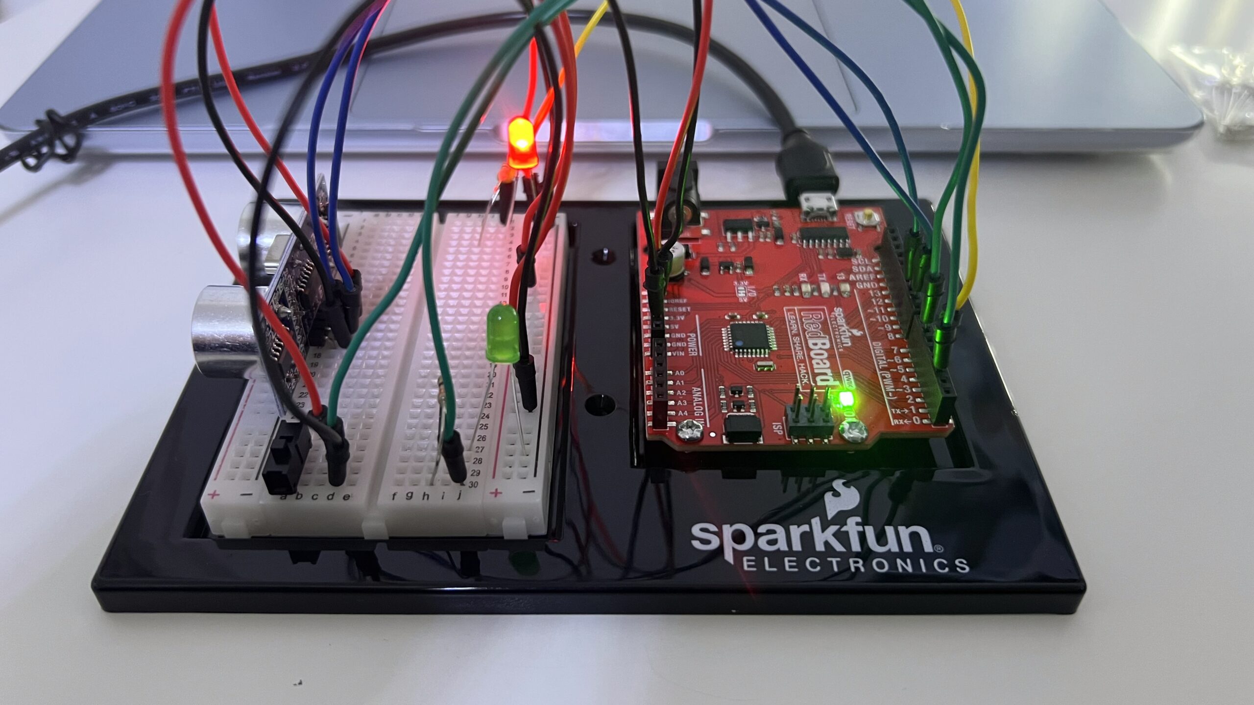
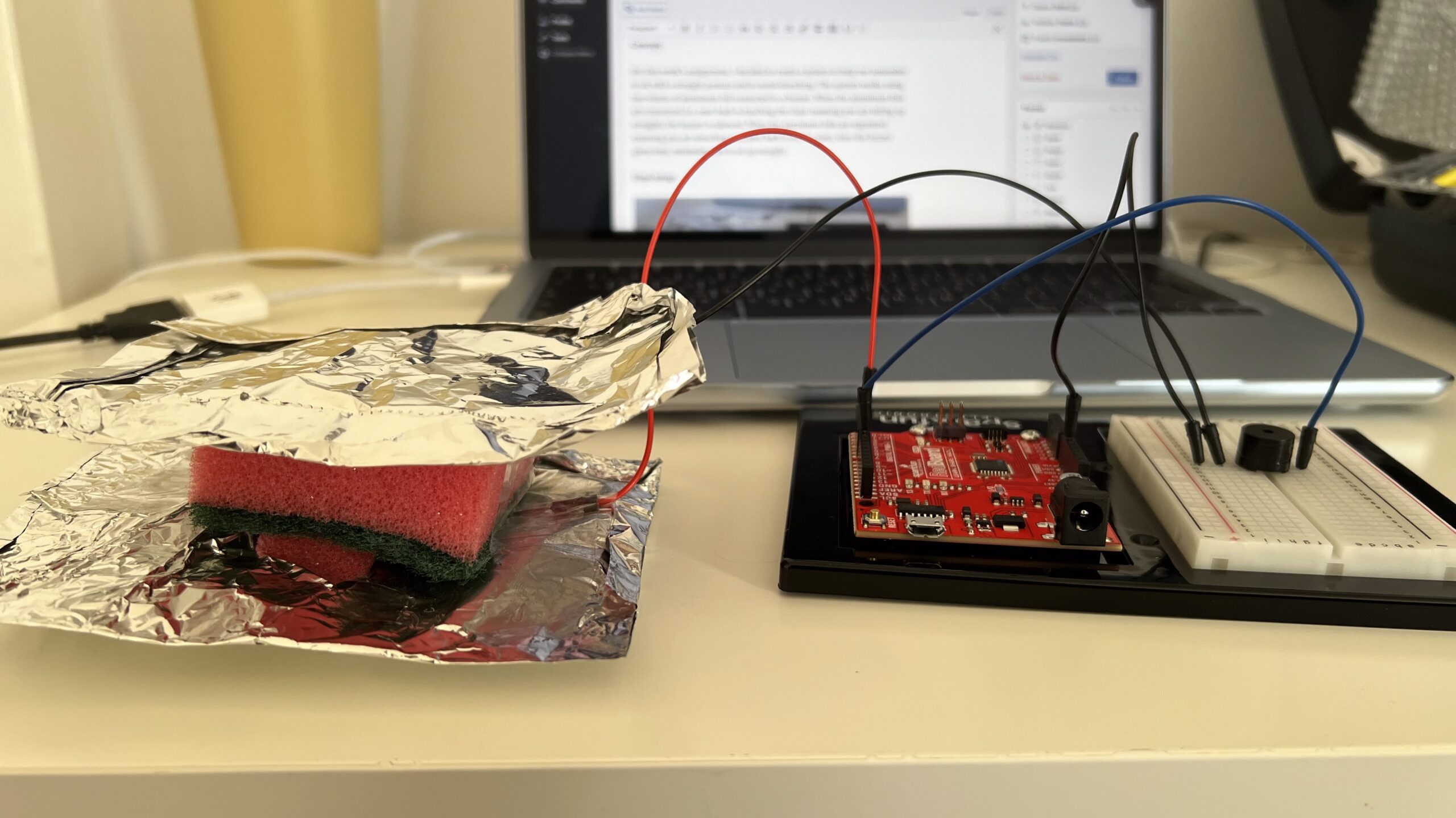
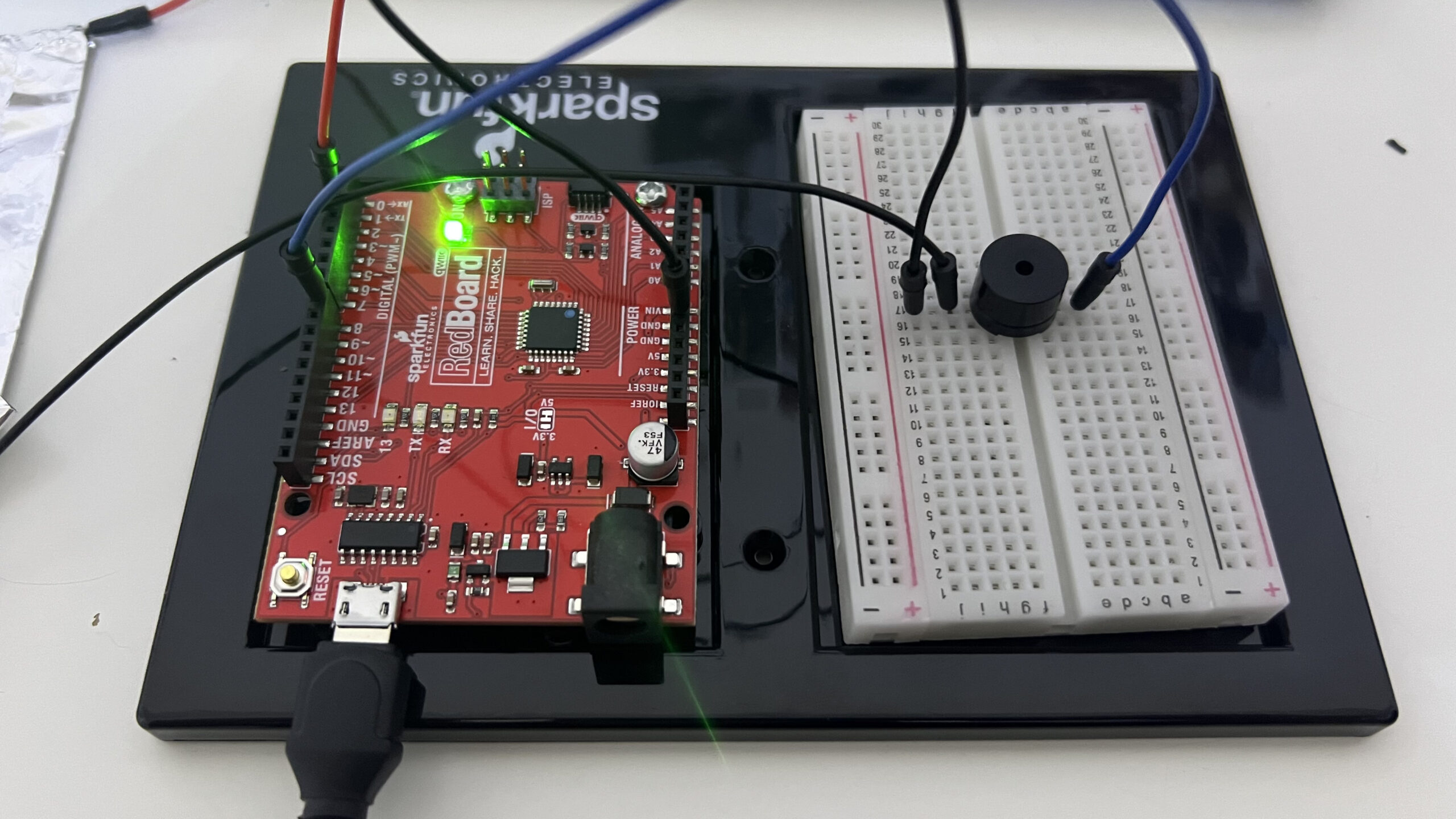
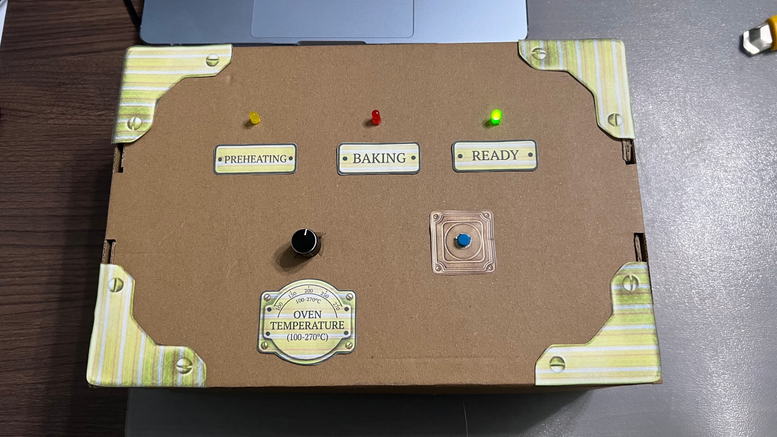
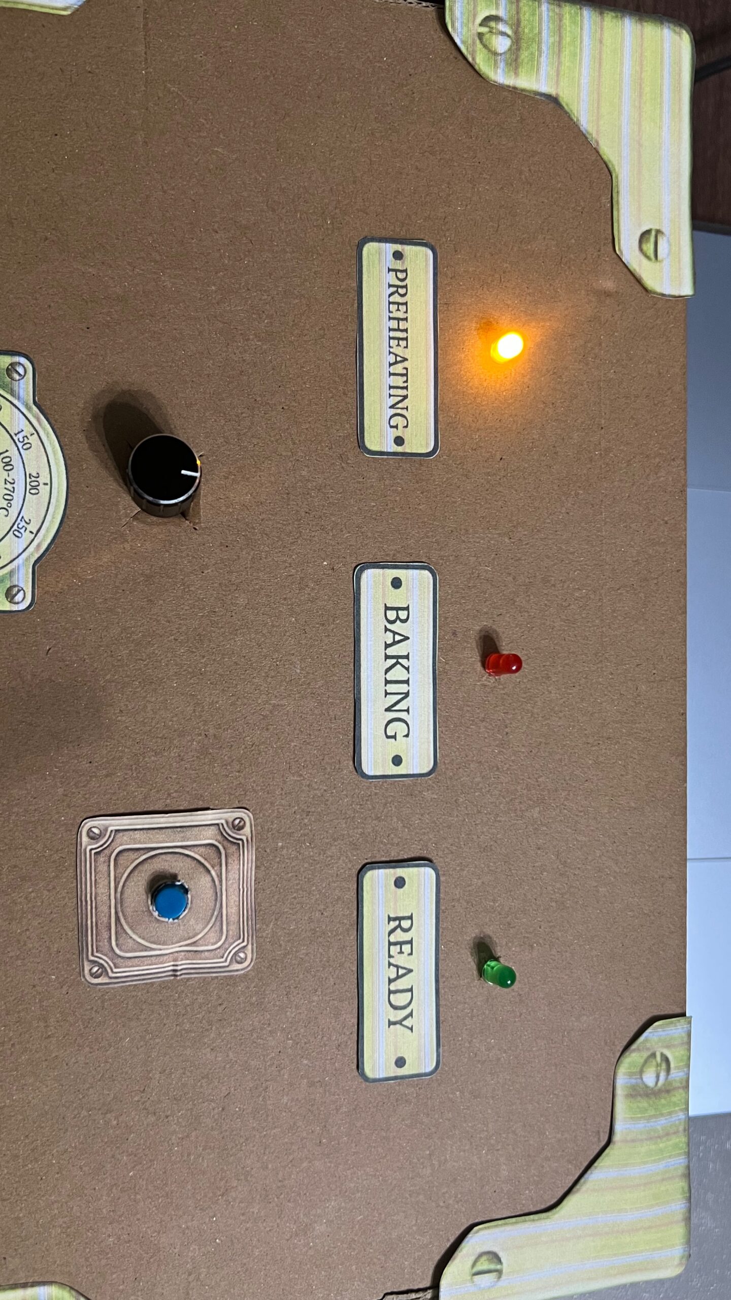
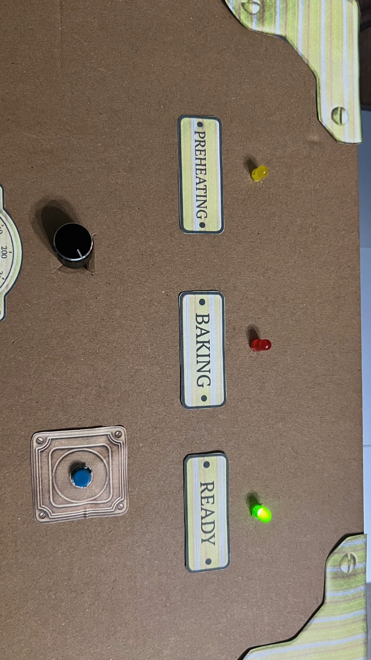
Control box set up:
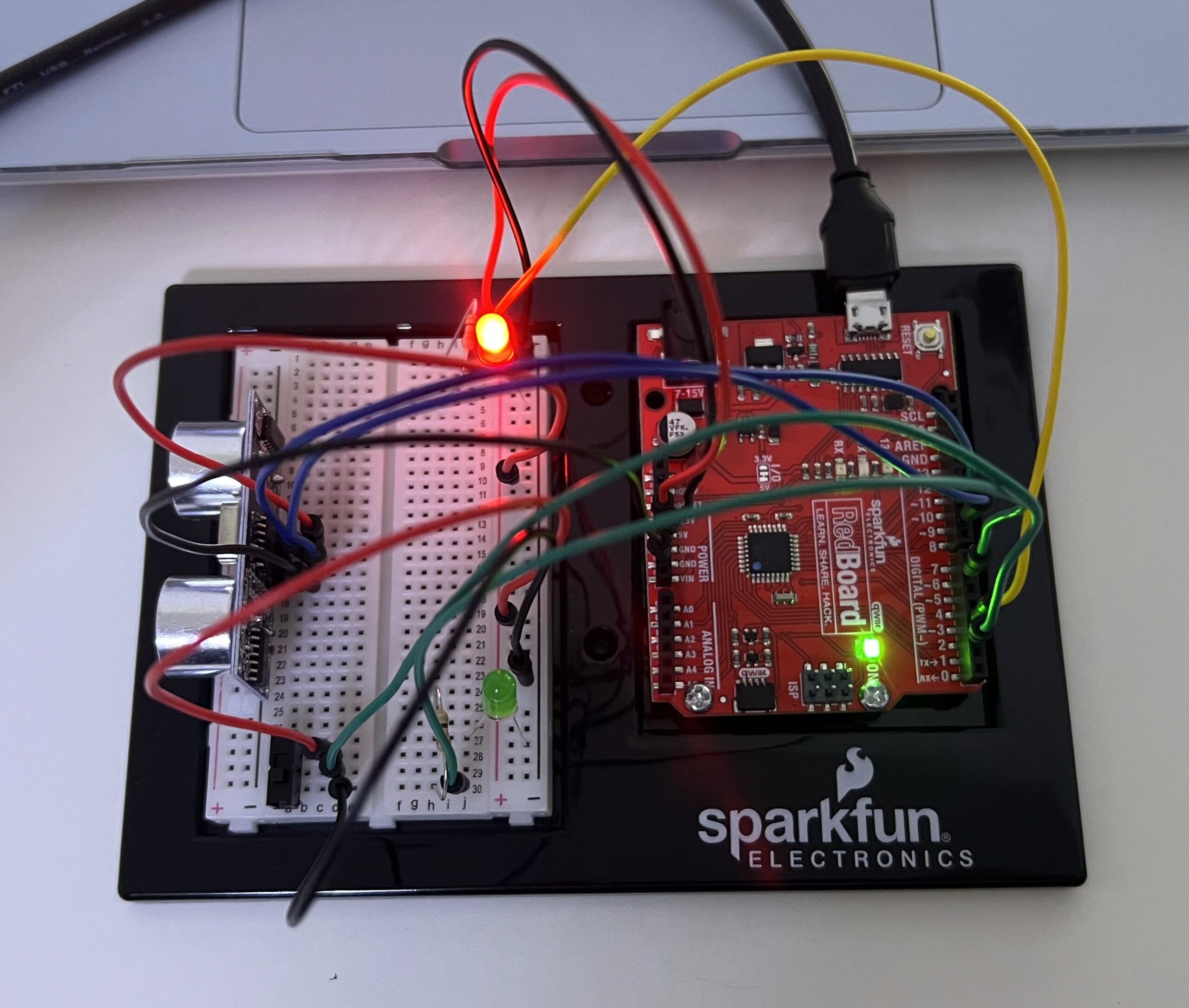
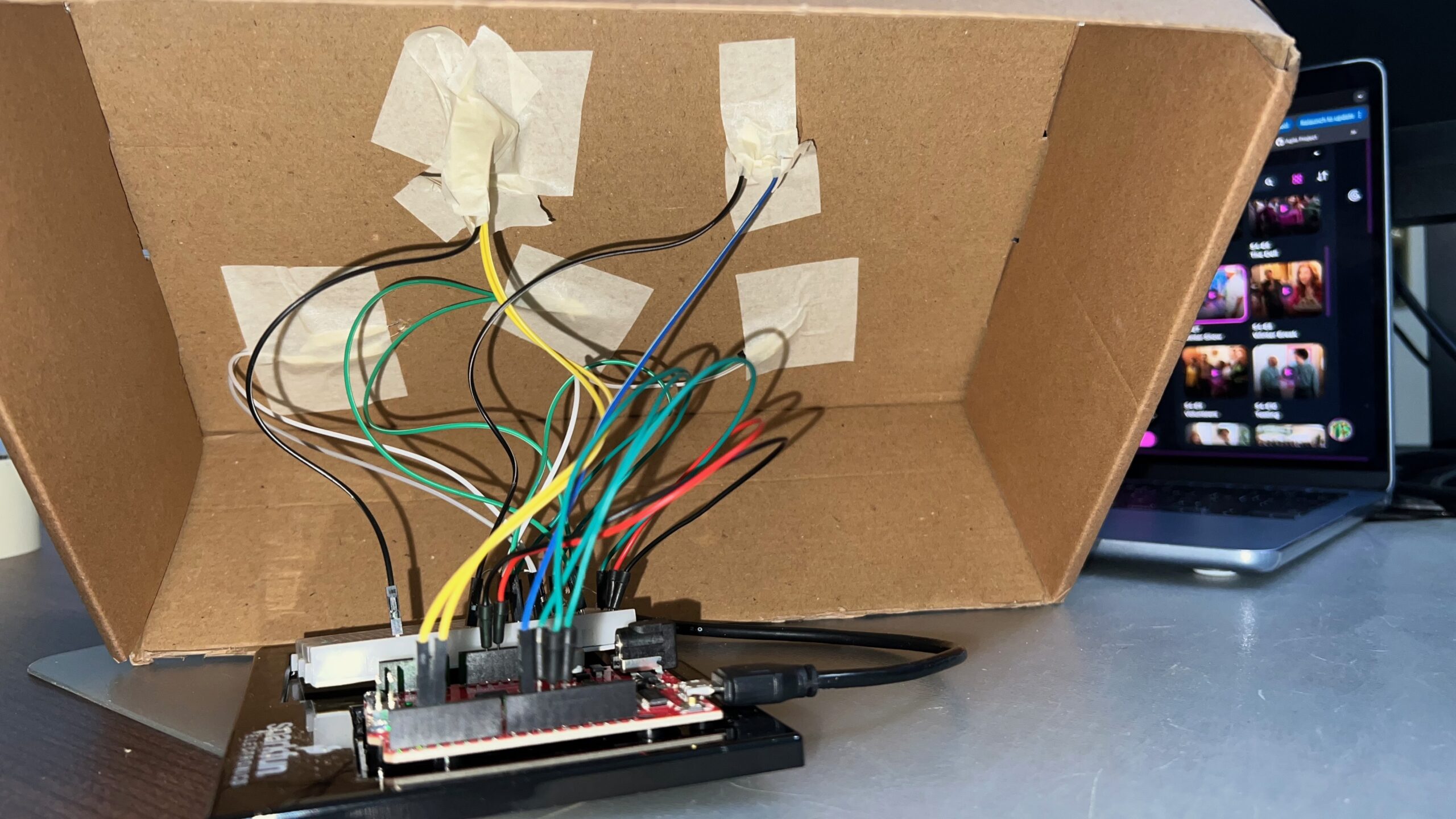
Under the box:
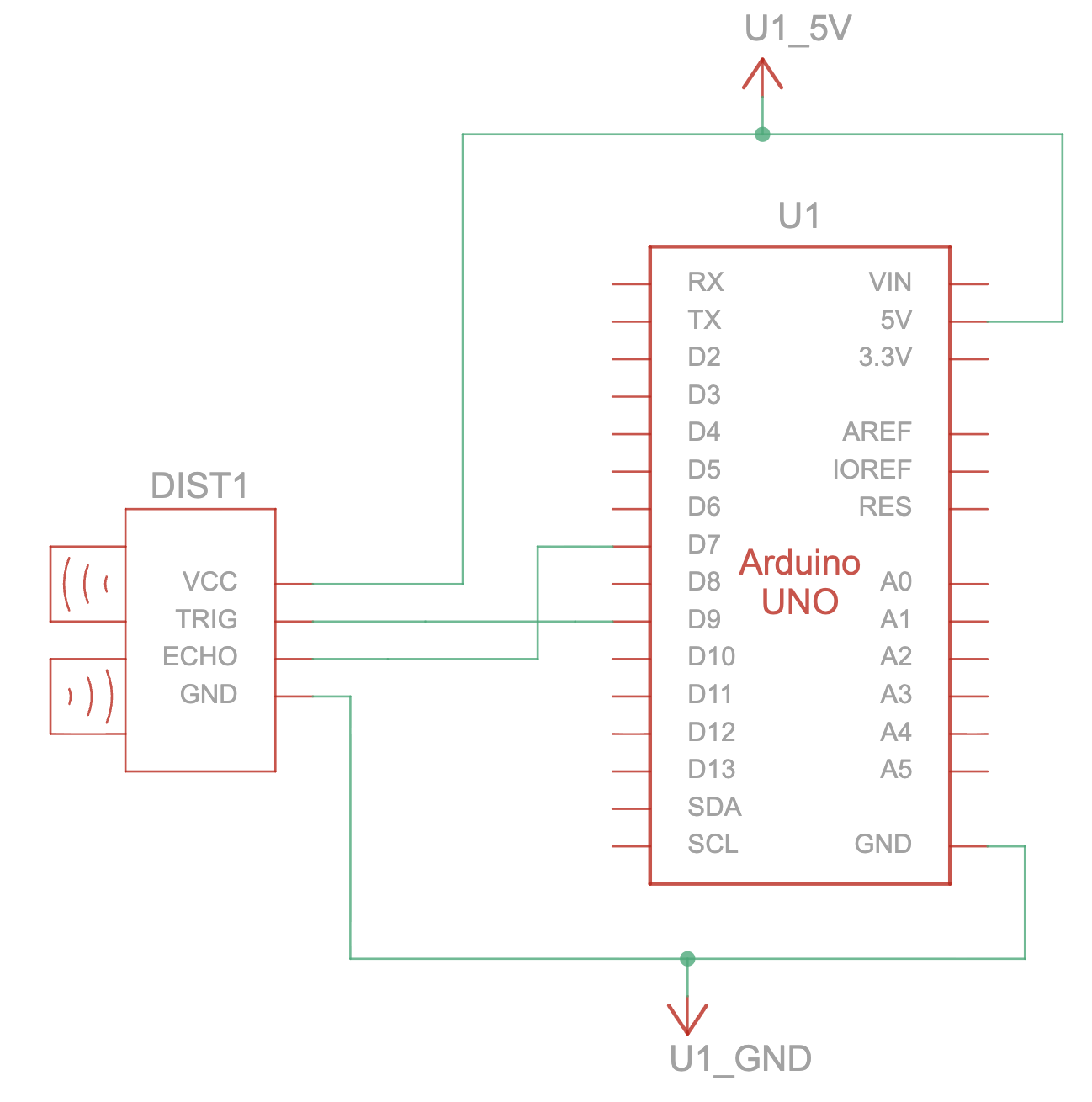
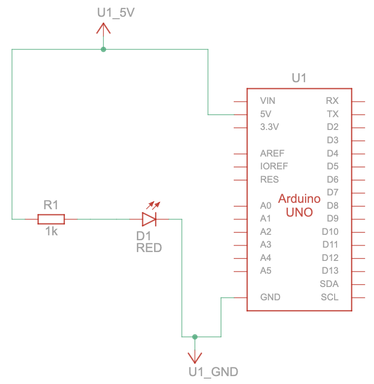
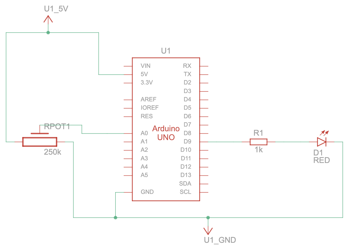
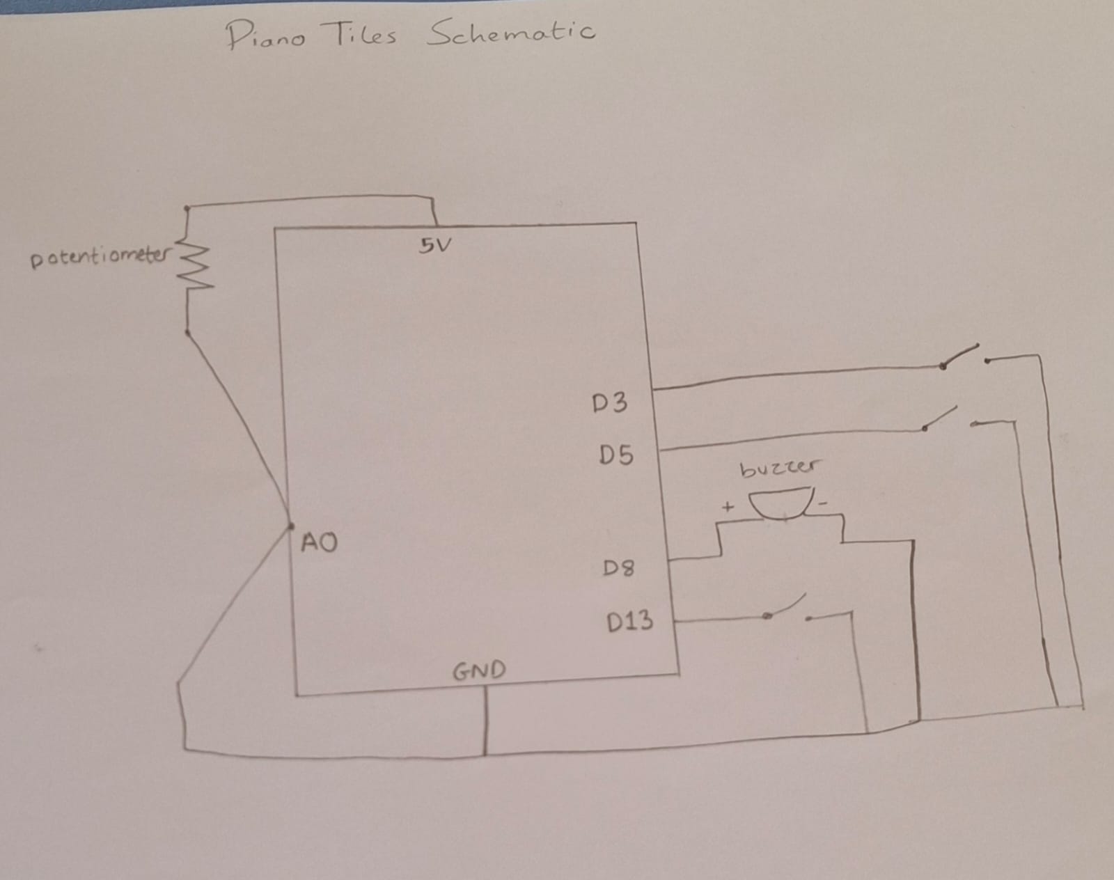
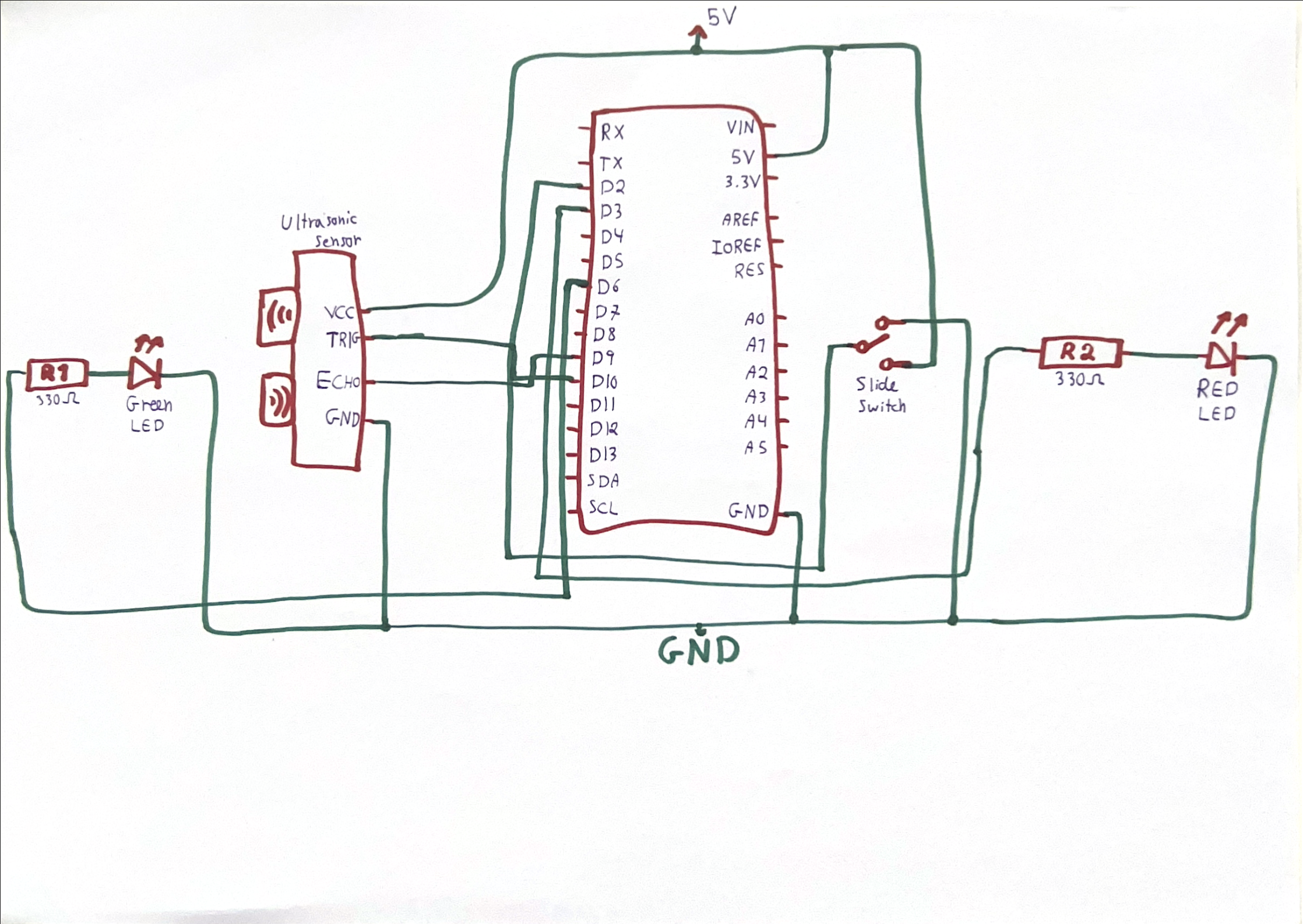
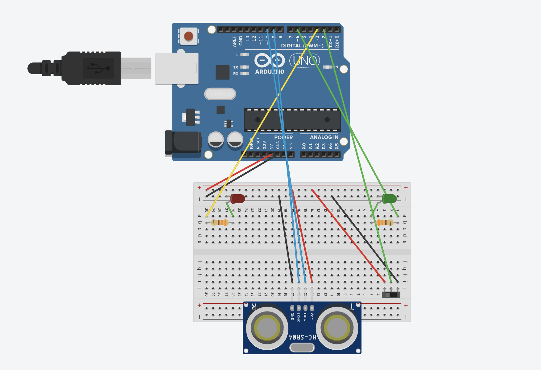
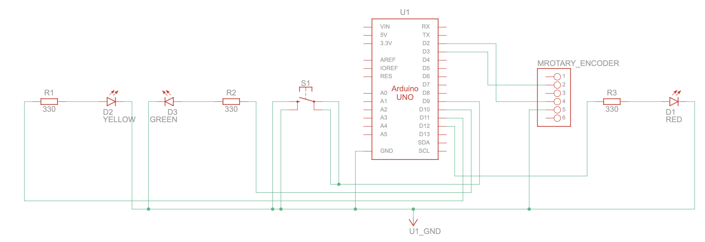
Schematic
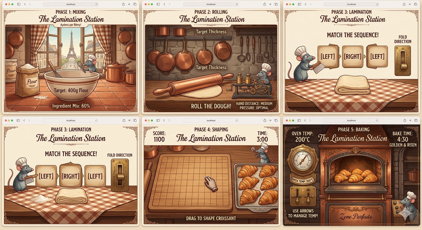
Screenshots from the p5 sketch:
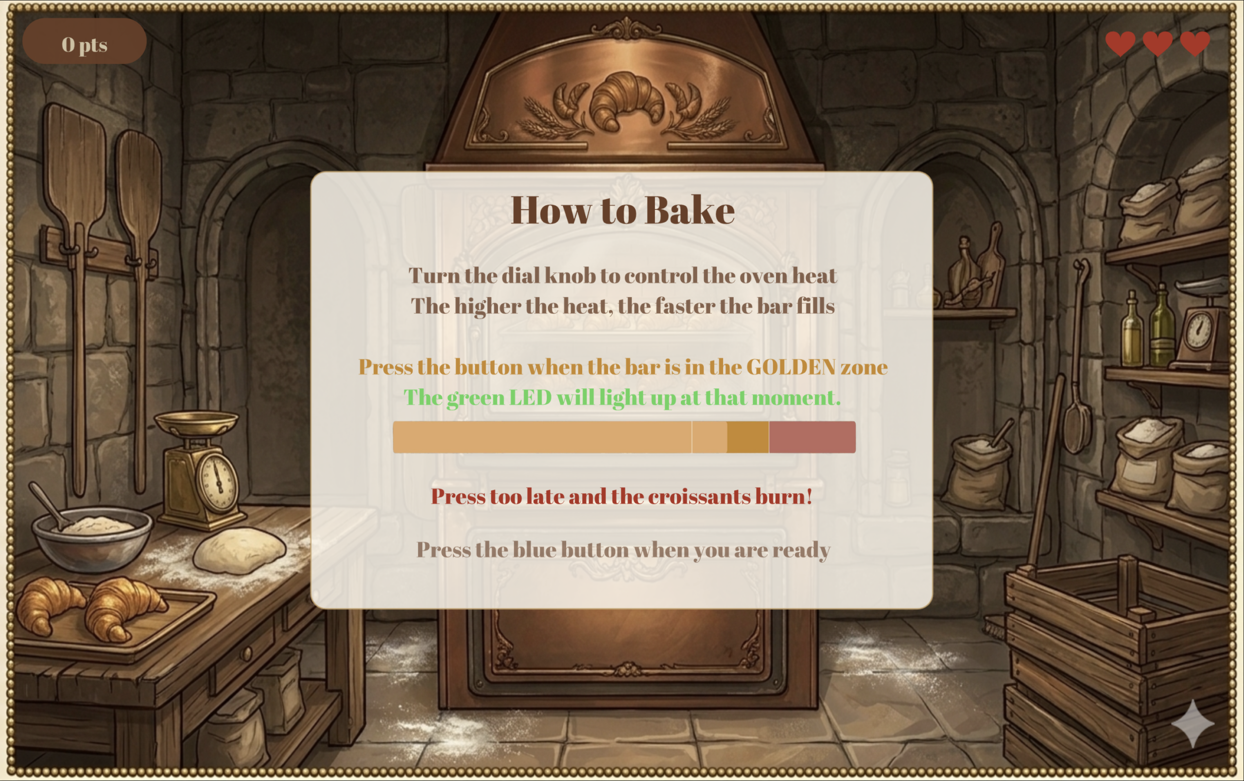
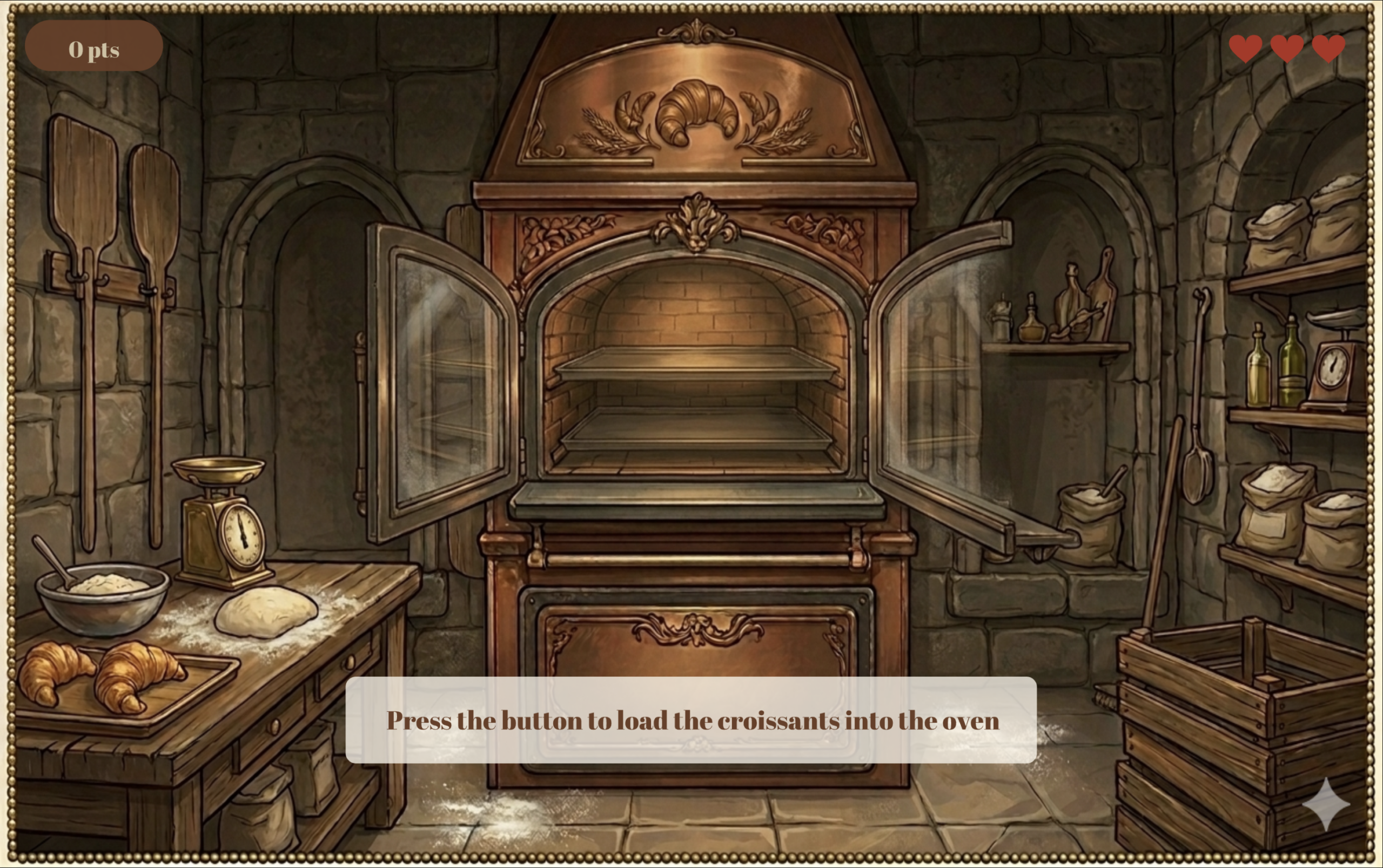
Below is the first screen the user sees after the home screen. It provides instructions for the first part of the game: the baking stage.
Below is the second screen in the game. The user must click the button on the control panel to load the croissants into the oven.
During the loading stage, p5 sends a signal to Arduino to turn on the yellow LED light, signaling the preparation stage.
After that, the user controls the speed of the progress bar using the encoder dial. The higher the temperature the faster the bar moves. The user must click the button when the progress bar is in the “Perfect” section to earn full points. Clicking too early makes you lose points, and clicking too late costs you 1 of the 3 lives you get (displayed in the top right corner) and the game takes you back to the screen above to load a new batch of croissants into the oven.
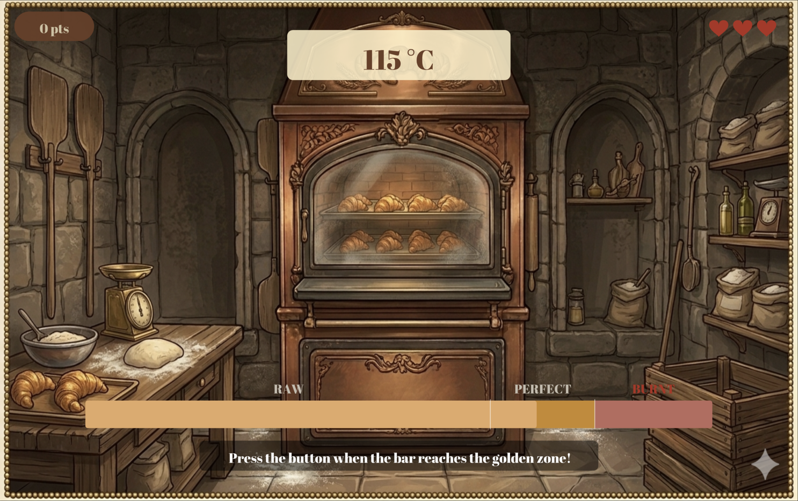
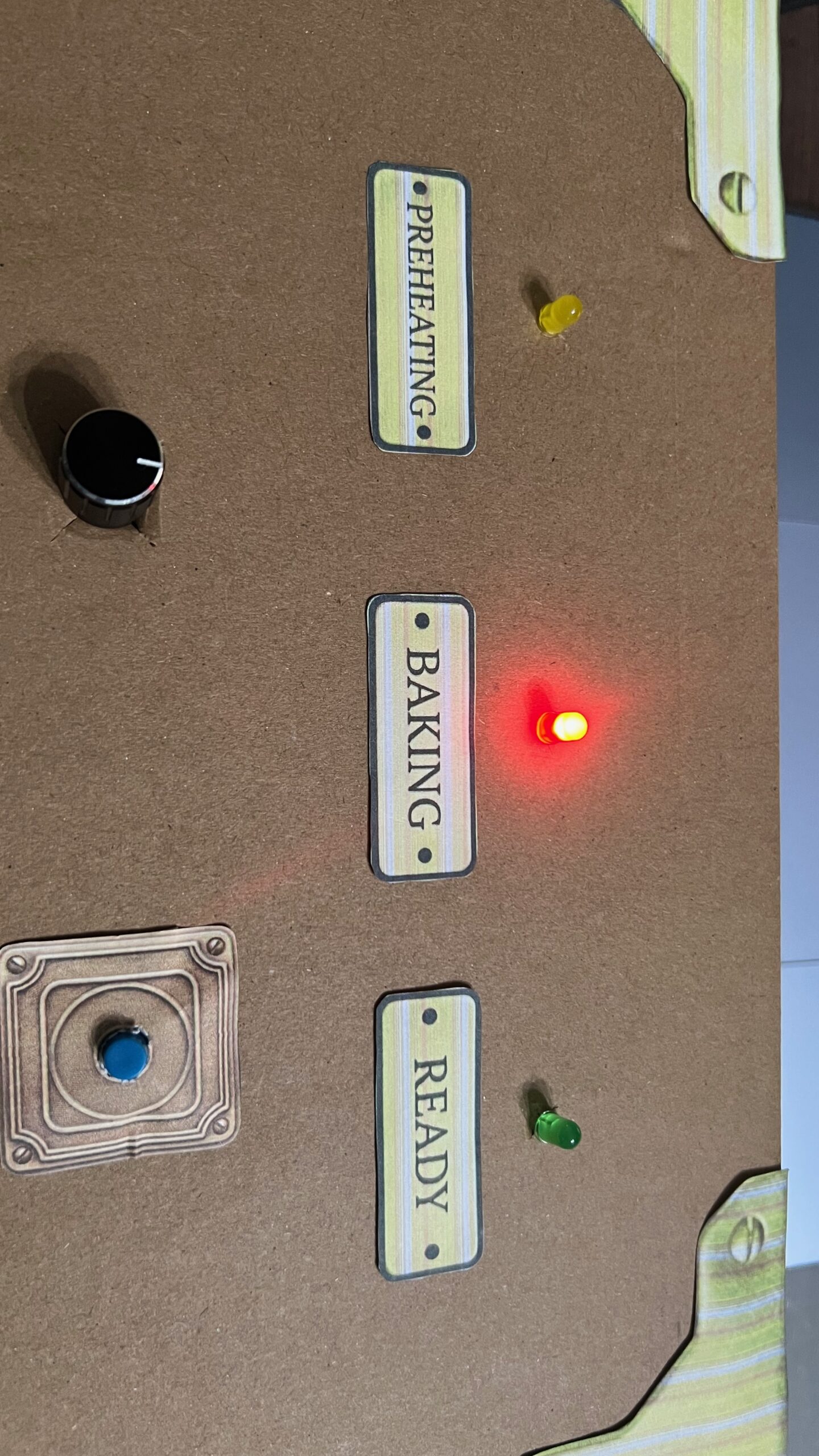
As soon as the player enters the baking stage, and before the progress bar enters the “Perfect” section, p5 send a signal to Arduino to turn on the red LED light, signaling the baking stage.
When the bar enters the “Perfect” zone, p5 send a signal to Arduino to turn on the green LED, indicating the croissants are ready.
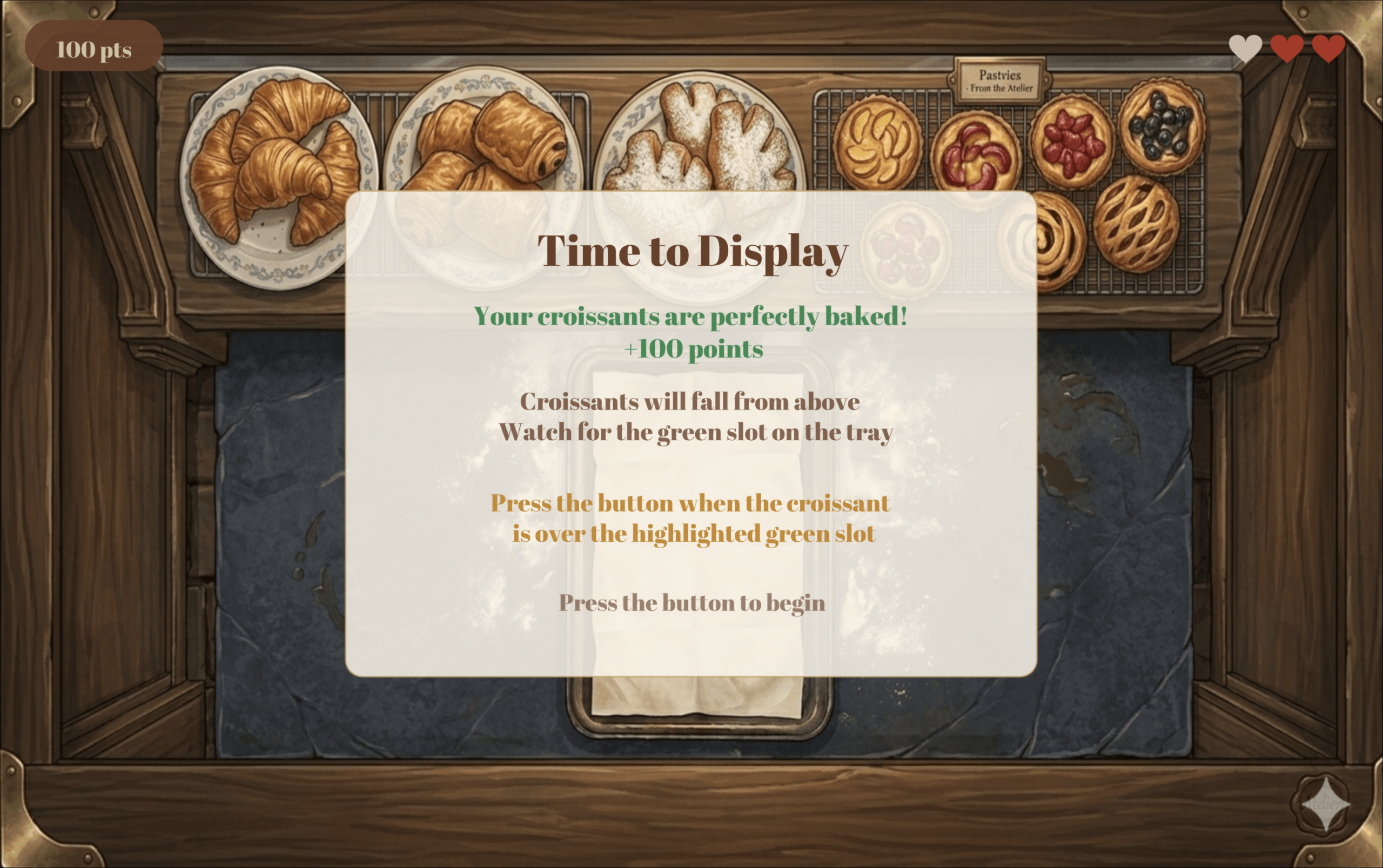
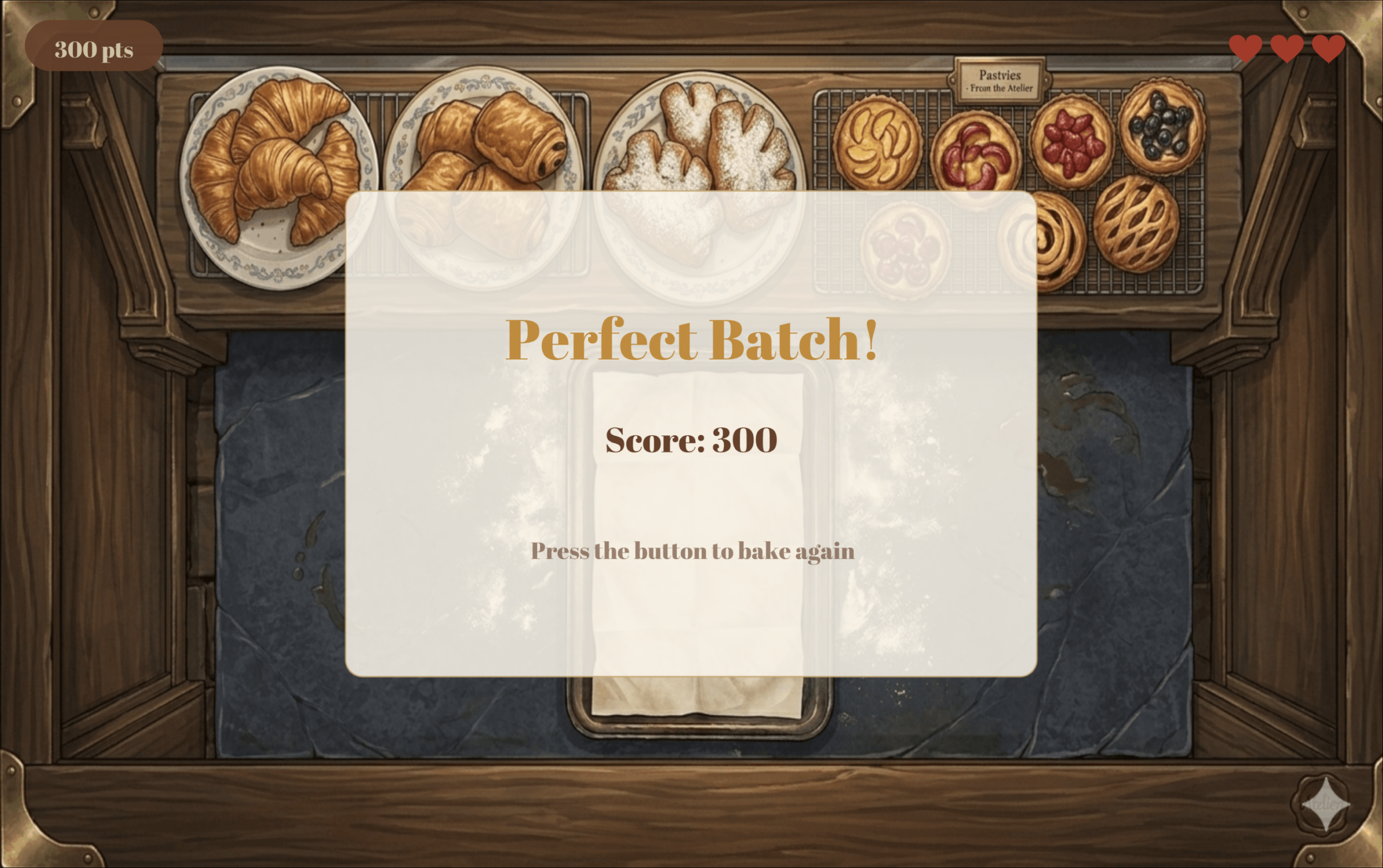
If the user perfectly bakes the croissants, the screen below is displayed, giving the user full points and instructions on how to place the croissants for display.
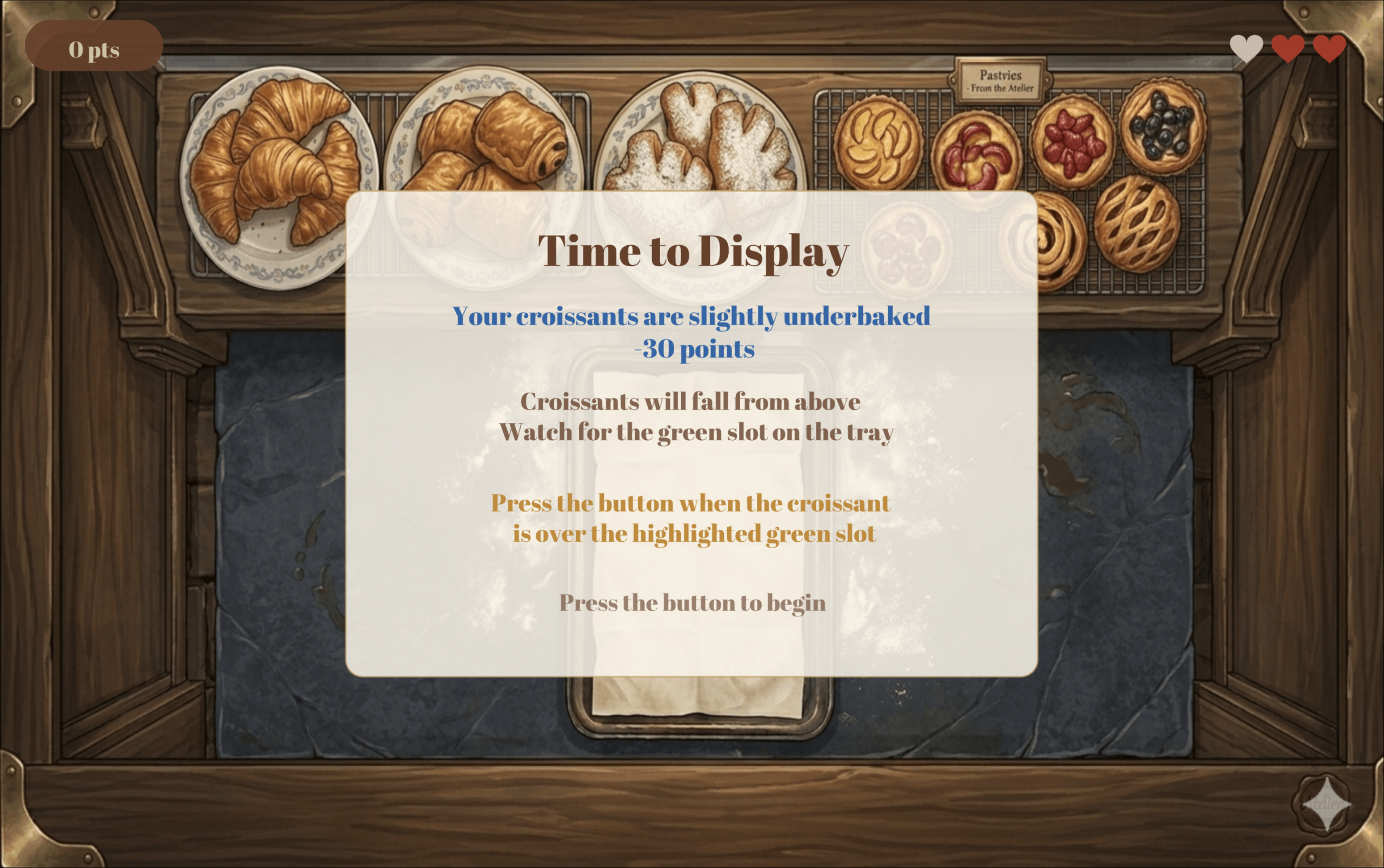
If you underbake the croissants, then you lose 30 points, earning only 70 pts instead of 100. The screen below is displayed informing you of your result and the same instructions above on how to play the second and final stage of the game.
In this stage, you must place 6 croissants in their designated spots on the tray to get them ready for display. The croissant will be falling from the top of the screen, and the user must click the button at the right moment to correctly place the croissants.
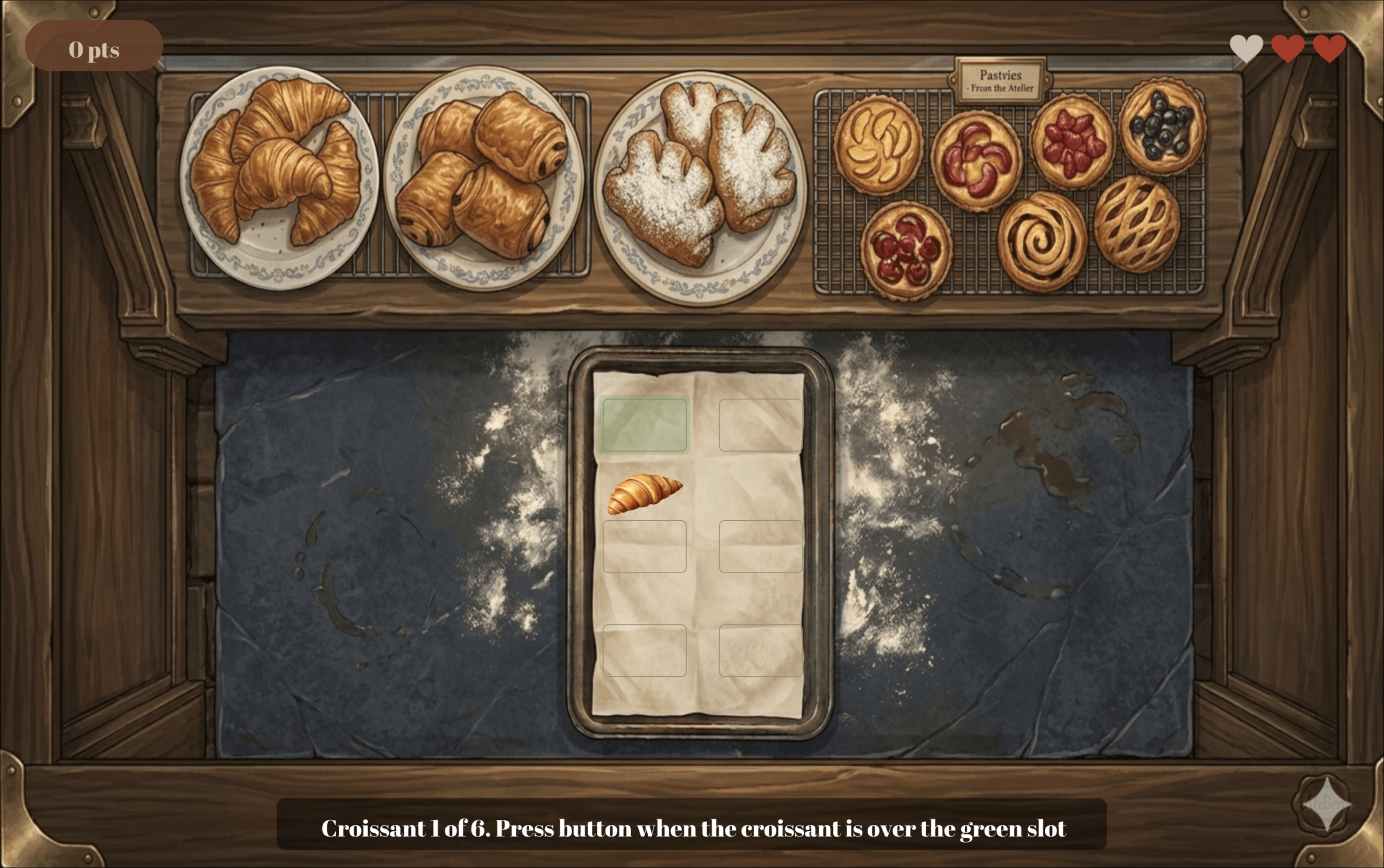
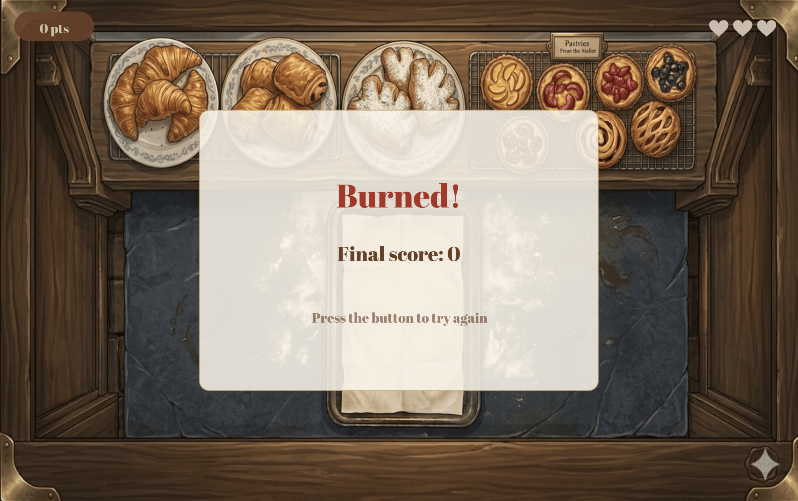
Failing to place the croissant correctly costs you a life, and once you lose all 3 lives you have, then the game is over and the game over screen is displayed.
Below is the winning screen.
Description of p5 Code
The code is split across eight JavaScript class files, each responsible for a distinct part of the game.
SerialComm handles all communication between p5.js and the Arduino. Every frame it reads the latest line sent from the Arduino over Web Serial, parses it into an encoder value and a button state, and validates the values before accepting them to filter out any garbage data sent on startup. It also exposes methods for sending single character LED commands back to the Arduino, opening the Chrome port picker, and resetting the encoder counter to zero at the start of each bake.
OvenScene manages everything that happens during the baking phase. It tracks the baking progress, calculates the fill speed based on the encoder value, detects when the golden zone is first reached to trigger the green LED, handles the button press result, plays and stops the timer and ding sounds at the right moments, draws the temperature display pill, and animates smoke particles once the croissants start to burn.
ProgressBar is a standalone class that draws the baking bar at the bottom of the oven scene. It divides the bar into three colour coded zones: blue for raw, gold for the perfect window, and red for burnt, and animates the fill colour shifting from cream to red as the croissants get closer to burning.
FallingCroissant represents a single falling croissant during the display phase. It stores the croissant’s position and fall speed, moves it downward by its speed each frame, checks whether it is within the tolerance zone of its target slot, and detects when it has fallen past the bottom of the tray without being placed.
TrayScene manages the full display stage of the game. It maintains an array of six slots and tracks which ones have been filled, spawns a new falling croissant aimed at the current target slot, checks button presses against the zone detection from FallingCroissant, increases the fall speed slightly after each successful placement to make the game progressively harder, and sends green or yellow LED commands to the Arduino in real time depending on whether the croissant is currently over the target zone.
Header draws the score pill and life hearts that sit on top of every game scene. It uses push() and pop() to isolate its drawing state so that text alignment and rect mode settings from other scenes do not bleed into the header display.
GameManager is the main class which controls the flow of the game. It cycles through nine game states: connect, main menu, baking instructions, oven loading, baking, display instructions, display, win, and game over, drawing the correct background image and calling the correct scene method each frame. It also handles score tracking, life management, screen flash effects, and game resets.
Finally, sketch.js declares all global variables, loads every image, font, and sound file in preload(), initializes the GameManager in setup(), delegates all drawing and logic to it in draw(), and handles the two keyboard shortcuts: `F` to toggle fullscreen and `SPACE` to open the Arduino connection dialog.
Description of Arduino Code
For the encoder, instead of checking its value in the main loop like I originally tried to do with a potentiometer, I used hardware interrupts. This means the Arduino immediately runs the read_encoder function the moment either encoder pin changes, without having to wait for the loop to get to it. This was really important because encoders fire very fast and the loop was simply too slow to catch every click reliably. Inside read_encoder, a lookup table of 16 possible pin state combinations is used to figure out which direction the encoder was turned, and a counter variable goes up or down accordingly. The counter is clamped between 0 and 100 so no matter how much the player spins the dial, the value always stays in a range that p5.js can work with. There is also a fast turning detection built in. If two clicks happen within 0.025 seconds of each other, the counter jumps by 3 instead of 1, making the dial feel more responsive when spun quickly.
For the button, the code detects the exact moment it goes from unpressed to pressed rather than reading it continuously, so holding the button down only counts as one press. This was important for the game because a lot of the interactions are time sensitive and a held button registering multiple times would completely break the logic.
Every 50 milliseconds, the Arduino sends a line to p5.js in the format “counter,buttonState” (for example `75,1` means the dial is at 75 and the button was just pressed). On the other side, p5.js sends back a single character (`Y`, `R`, or `G`) and the `setLED` function turns on the matching LED and turns the other two off. The special character `X` resets the counter back to zero, which happens at the start of every new bake so the player always starts from low heat.
Aspects I am Proud of
Considering the simplicity of my game logic, I wanted to focus my attention on the design, aesthetics, and user-friendliness. Since I usually do not get to be really creative for my coding projects in my CS classes, I wanted to take this opportunity to create something visually appealing.
I spent a lot of time with Gemini asking it to generate the images for the game until it generates exactly what I need. When it failed to do so, I used different scraps it generated for me and designed the exact image I had in mind on Canva. I also spent some time on the audio: finding the audios I need, converting them to mp3, and trimming them to my liking.
Additionally, the most time consuming part of this project was ensuring all the elements and text on the p5 sketch were placed exactly where I needed them and relative to the window size. I spent hours fixing different numbers to get everything exactly where I wanted it to be, running the sketch at least 100 times for sure.
Finally, I wanted to ensure I created a great user experience. I know how frustrating it is when you struggle to understand the logic of a game and how it works; therefore, I wanted to use this project as a chance to practice creating clear instructions with visuals on how to play. I tested my work on my sister by giving her no context on how to play and seeing if she can figure it out only by reading the instructions on the sketch, and she did!
Areas for Improvement
Despite being proud of the final product and its aesthetics, I am actually not the happiest with my concept. I wanted to create a more unique project idea, but was having a bit of a brain fog and could not think of anything. I also would have liked to create a better control box to hold my Arduino components, but I had to work with what I could find around me while keeping ease of use in mind.
References
Arduino:
Images:
-
- All images were generated by Gemini AI. Here is my very aggressive chat with it trying to have it generate what I want https://gemini.google.com/app/2face7d60f86aca4