Concept
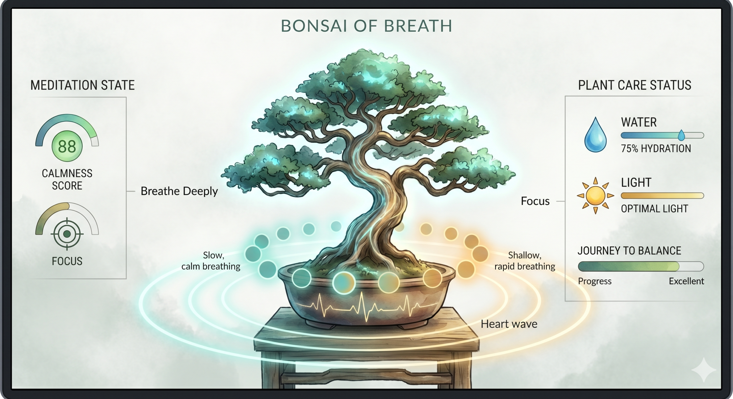
The final project is an interactive experience where the users physical body state and actions of caring for themselves will be interpreted to the growth of a digital Bonsai tree. The users breathing are monitored, to which the tree syncronizes, are interpreted into the growth of the tree. The act of drinking water will serve as hydration of the tree. The physical light conditions of the user’s environment will be reflected on the tree’s lighting conditions. This experience visualizes meditation and self care, turning it into something tangible and fun.
Images of experience
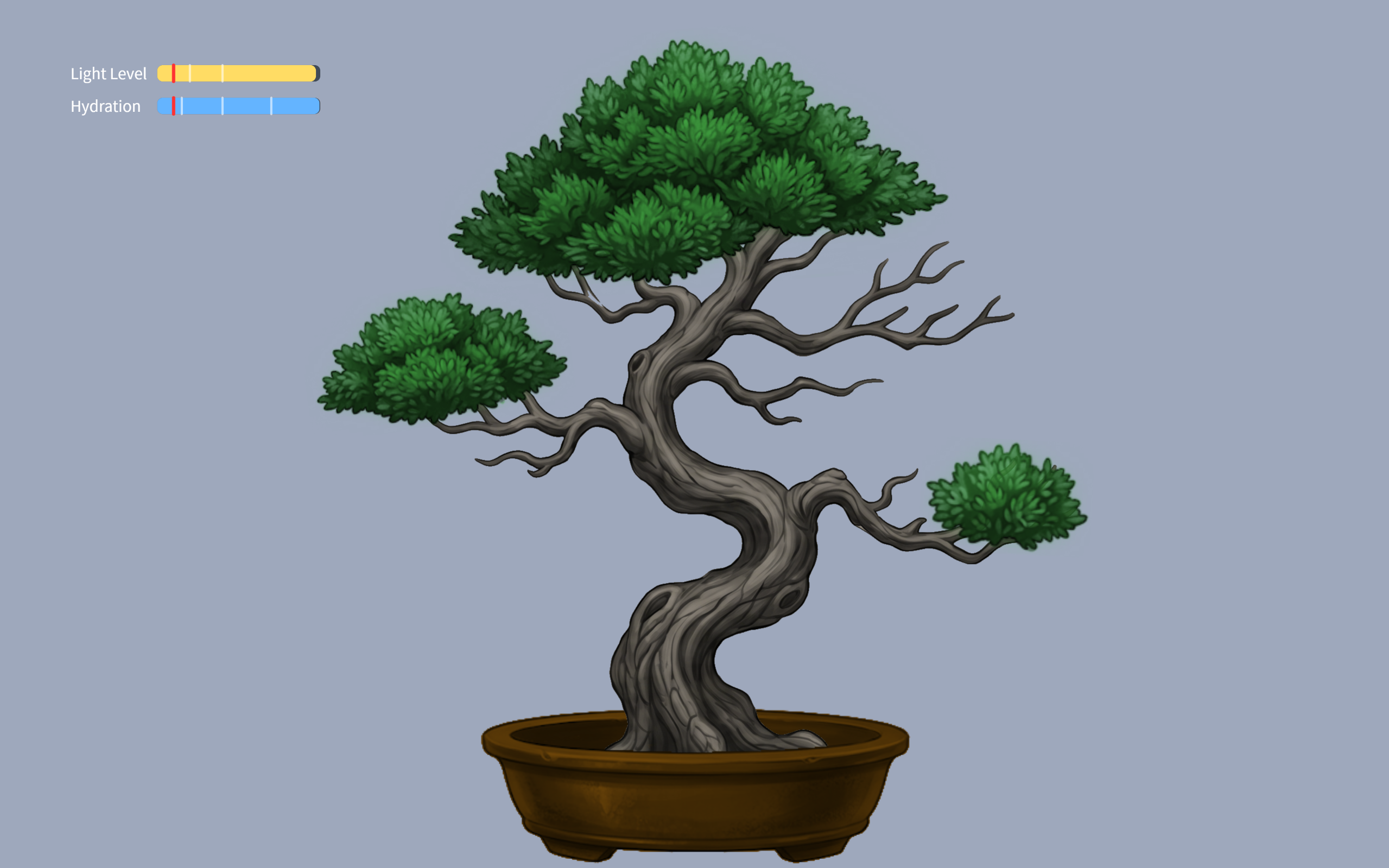
100-70% hydration tree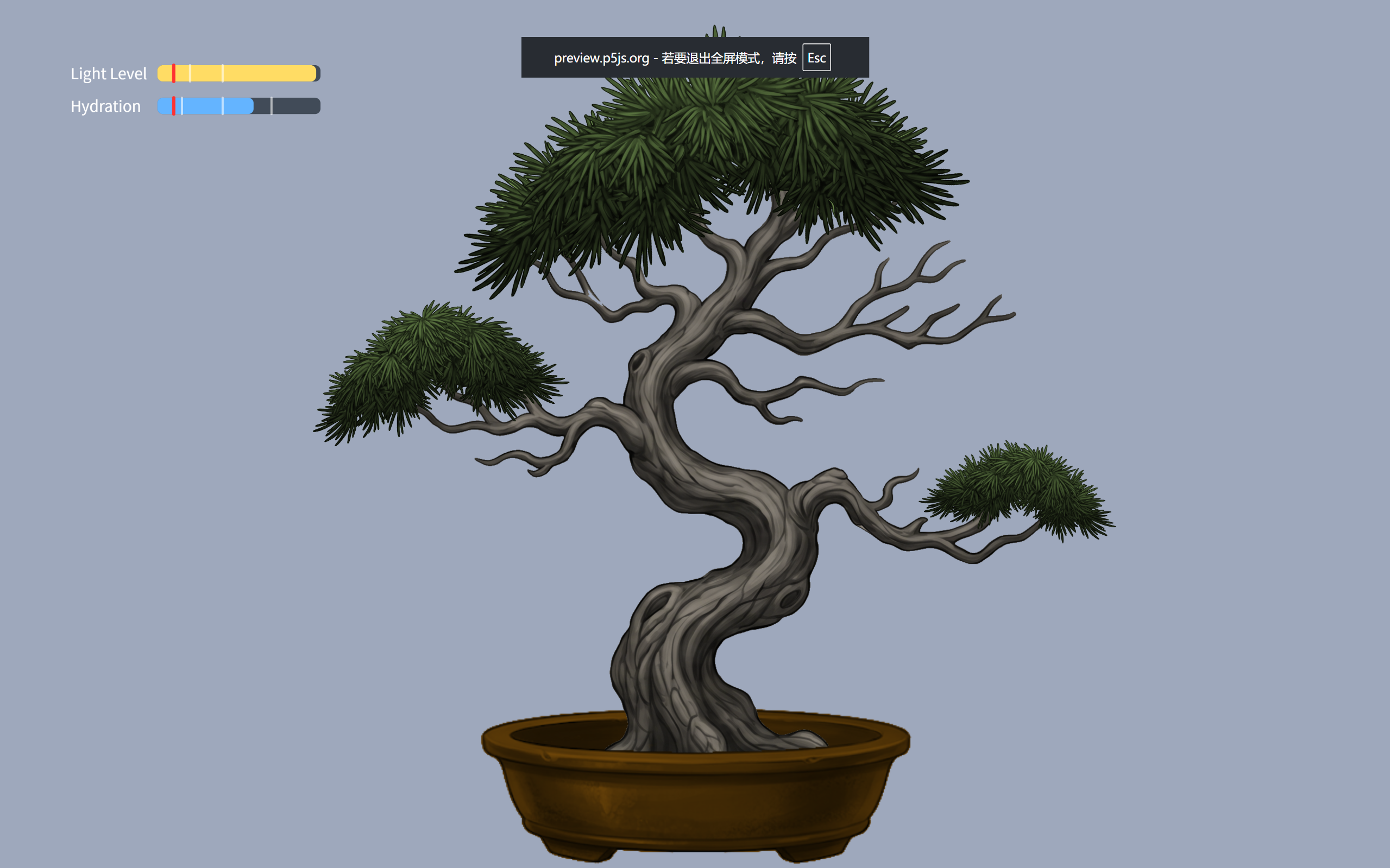 70-40% hydration tree
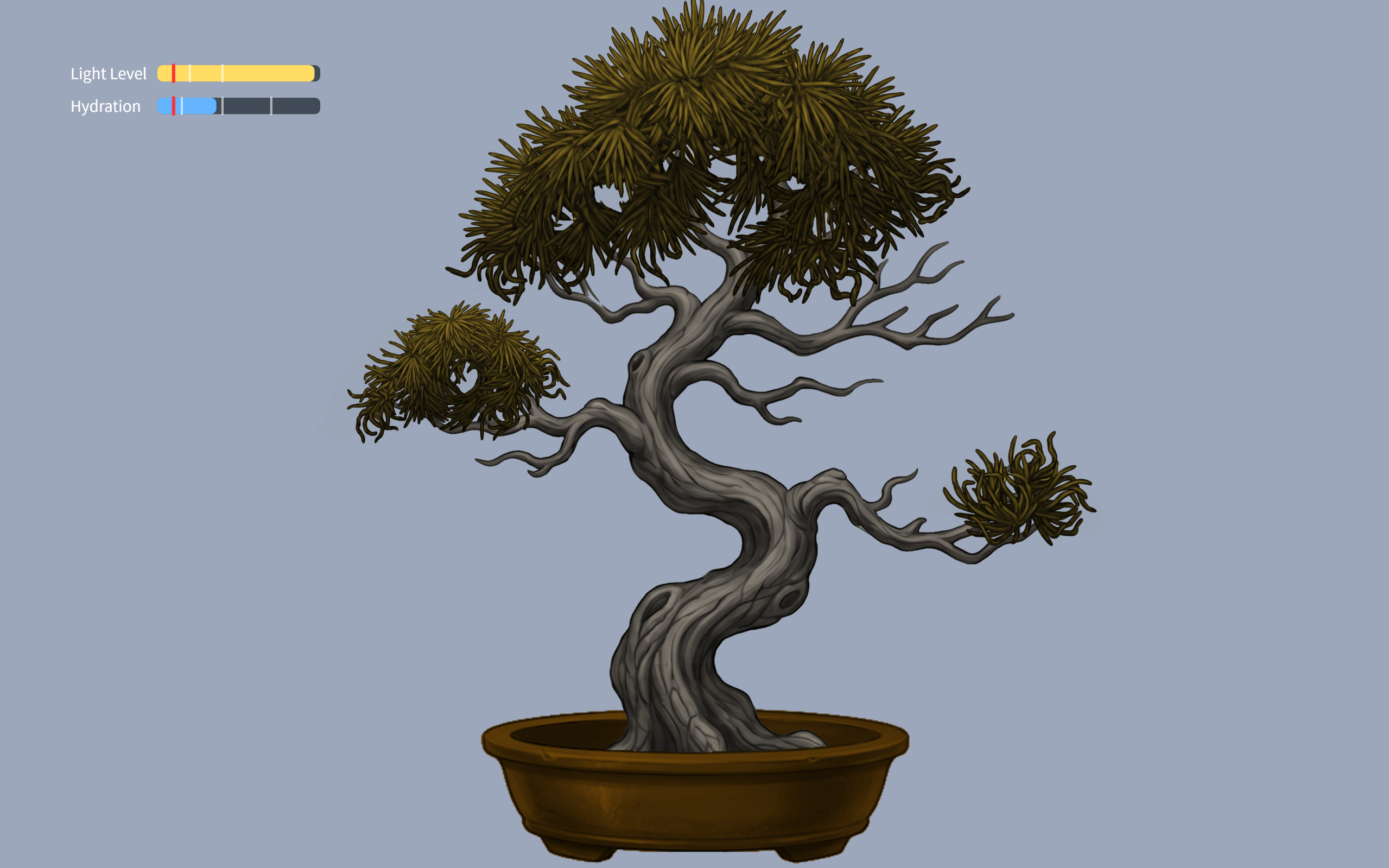 40-15%hydration tree
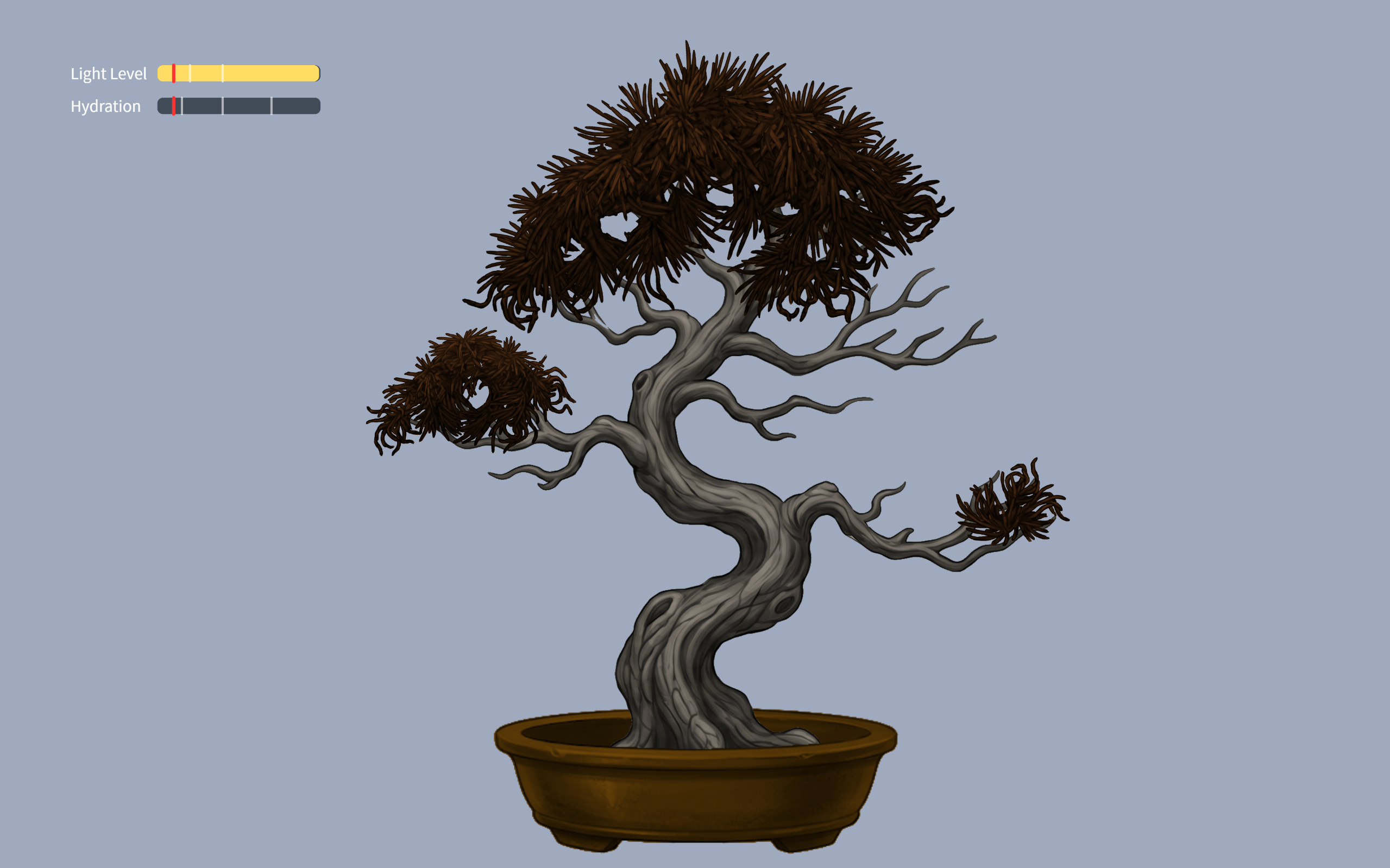 15-0%hydration tree
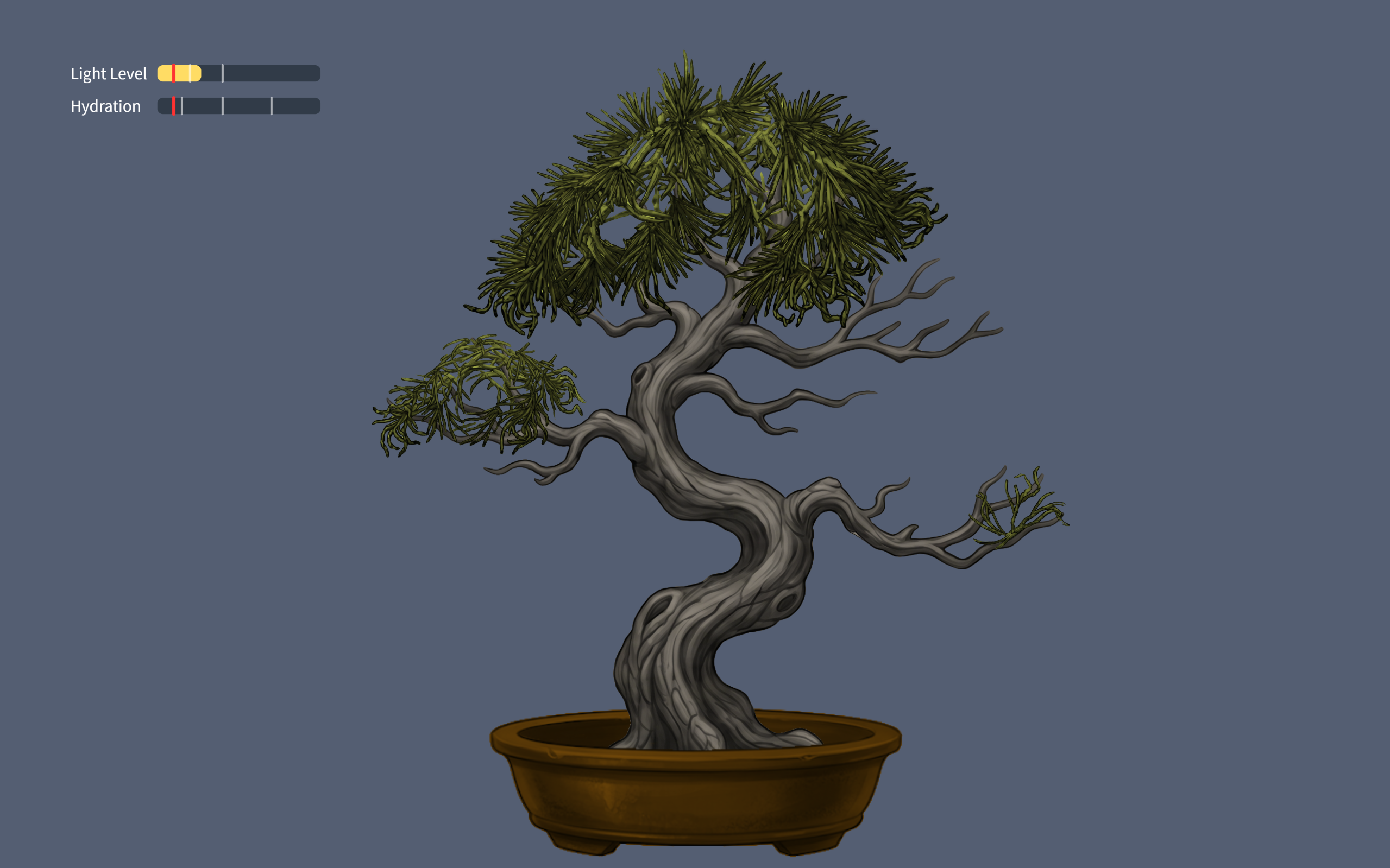 40-20% light tree
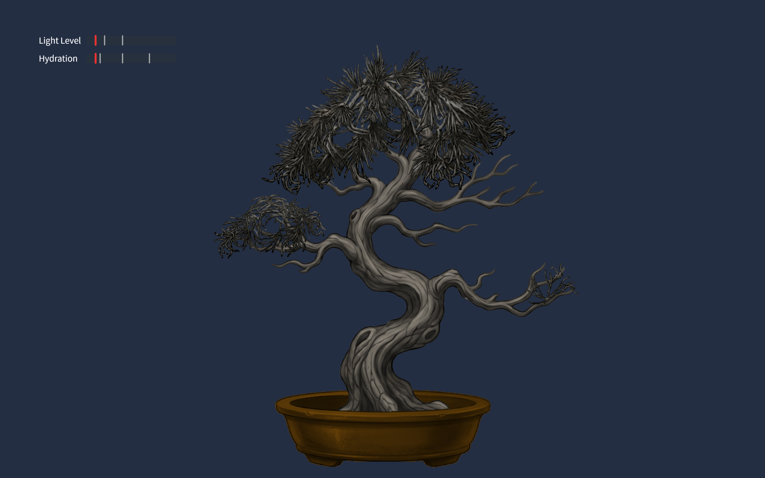 0-20% light tree
User testing
Implementations
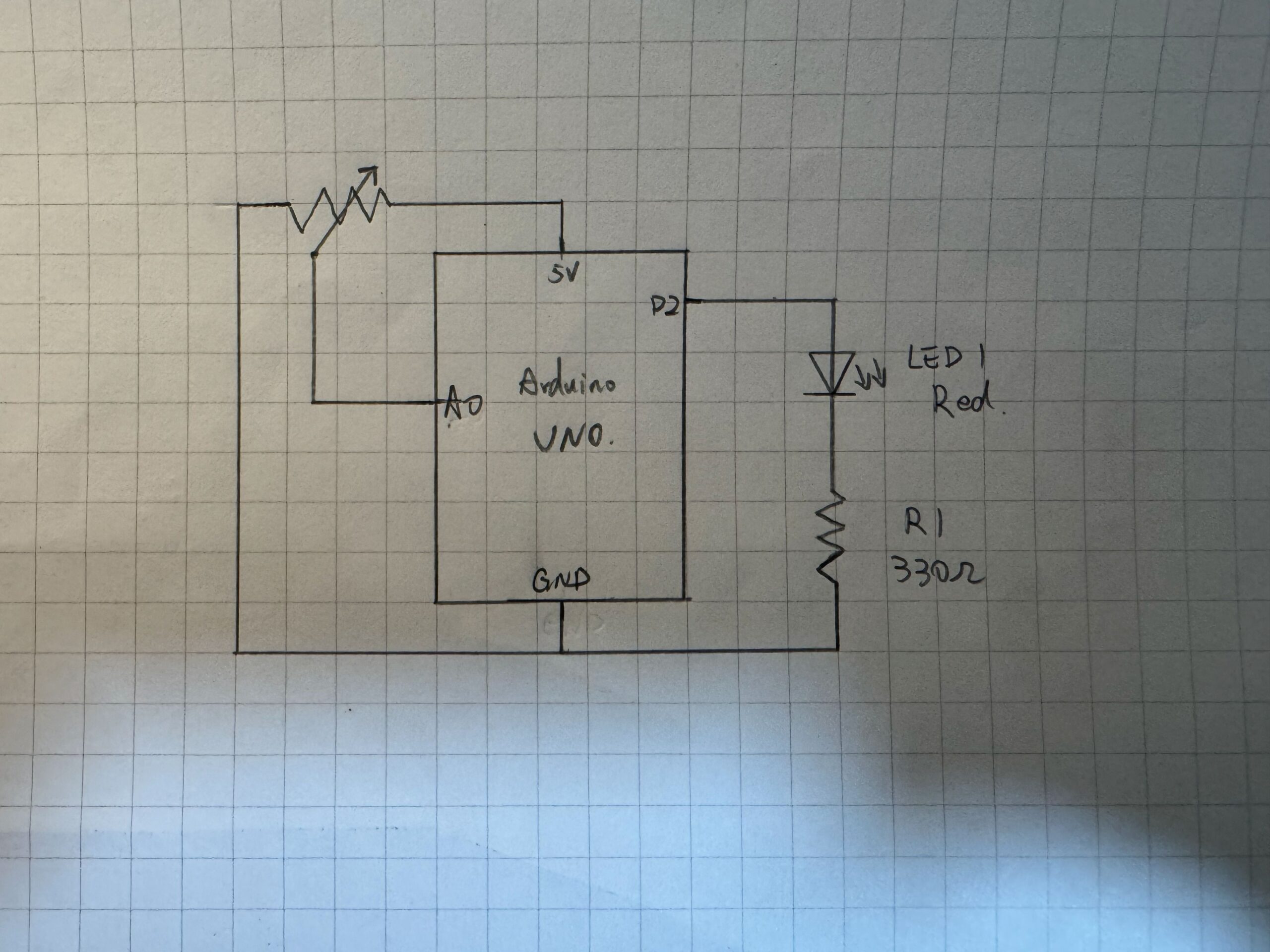
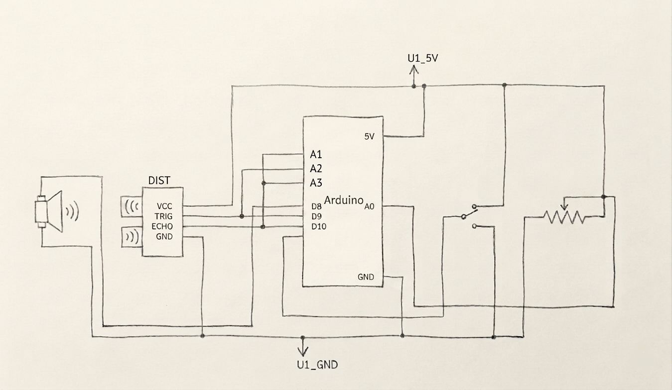
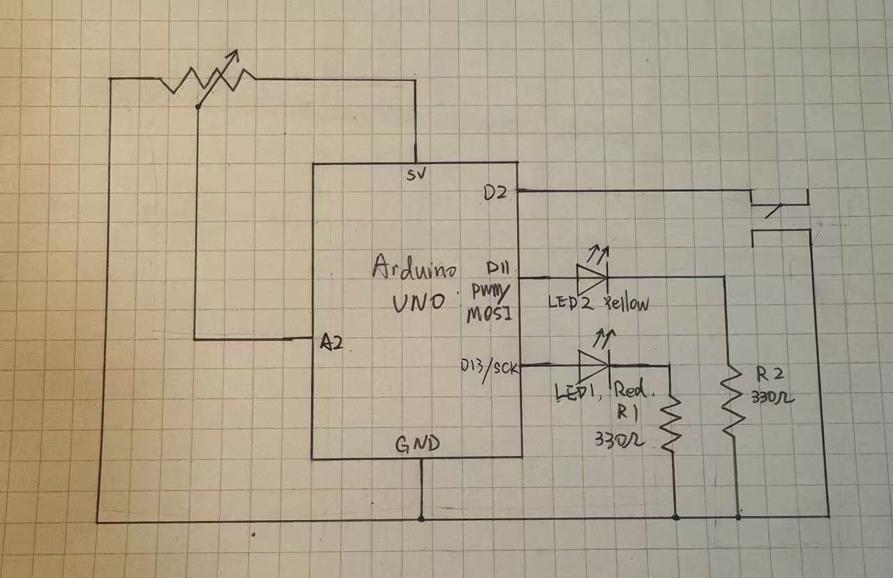
The design is based on self care of a person, so I need to convert human actions to inputs to the interface. Inputs include the users breathing (analog input), user drinking (digital input), lighting (analog input).
- Arduino code: My arduino code was realitively simple, it only inlcuded sensors sensing the inputs, and the bidirectional communication handshake.
if (Serial.read() == '\n') {
  digitalWrite(lightLedPin, lightState);
  digitalWrite(breathLedPin, breathState);
  digitalWrite(waterLedPin, waterState);

  // SEND TO P5
  int breathing = analogRead(A0);
  delay(5);
  int light = analogRead(A1);
  delay(5);
  int sipping = digitalRead(2);
  int buttonState = digitalRead(buttonPin);

  Serial.print(breathing);
  Serial.print(',');
  Serial.print(light);
  Serial.print(',');
  Serial.print(sipping);
  Serial.print(',');
  Serial.println(buttonState);
}
This is just the chunk for sending the data to p5.
github link: https://github.com/JingyiChen-jc12771/Intro-to-IM/blob/bc4afa47ce3d8aa52541bd046100ab28d2794849/final_project.ino
- p5 code: p5 code is very illuistration heavy, all the animations are in p5. I included callibration to users breathing conditions, the change of tree appearance when parametera changed, and all special effects triggered when drinking or focusing for a certain amount of time.
if (gameState === "instructions") {
  if (breathingValue < userBreathMin) {
    userBreathMin = breathingValue;
  }
  if (breathingValue > userBreathMax) {
    userBreathMax = breathingValue;
  }
}
This is a simple chunk of code where I calibrate the upper and lower limits of users breath strength to each indicidual player behind the instructions. this allows the tree pulsiong to work for everyone, and no one has to worry about being too much a fast breather.
the communication between p5 and arduino is basically arduino sensors sensing the suroundings and sendinbg them to p5 to apply to the art, and when p5’s math calculates that parameters are below 10%, it sends signals to arduino to light up the corresponding LED.
Some aspects that I am proud of
function checkFlowState() {
  if (lightPercent > 80 && hydrationLevel > 80) {
    return true;
  } else {
    return false;
  }
}
if (checkFlowState() === true) {
   isFlowing = true;
   spawnOrbs();
   growTreeToMax();
} else {
   isFlowing = false;
}
I am sort of proud of this piece of code. I am also proud of the breathing calibraation. This code here is the little “Easter Egg” effect I coded for player who are doing well. As long as they keep themselves and the tree in a good state, little magical balls of forest magic will flout up the screen, as an unexpected surprise.
Sources
https://www.youtube.com/watch?v=WDRokF_ZW9A
https://www.youtube.com/watch?v=KkyIDI6rQJI
https://www.youtube.com/watch?v=Qf4dIN99e2w
google gemini for image generation
AI use
Google gemini pro 3 helped me with: lerp() to create smoothing of breathing signals, virtual canvas to keep image sizes proportional, fade in fade out effects, understanding the breathing sensor reference code I found, finding correct speeds for parameters, and most importantly finding the cause of bugs.
Challenges
The most difficult part is actually debugging. It was not first writing the code itslef, it is how everything started failing once I initiated the running of the code. The serial communication produced some unexpected problems like not communicating at all or p5 and arduino screaming at each other and calsing the whole game to freeze. the fact that I am relatively new to both, especially arduino, makes it really hard to figure out what is going on in the code.
Future Improvement
What I would want to imporove in the future might be the animations. My current experience is based on images generated by gemini, and the fade in/ fade out effects were not the mast ideal. Though the tree pulses with the user this lack of animation stilkl makes the experience feel less lively. I would hope to ba able to upgrade that to make it more immersive.