Concept / Description
My project was inspired by simple robots / AI from the 90s and early 2000s (like the Tamagotchi pets) made to just be fun toys for kids. In our current age, we’re so used to advanced AIs that can complete complex thoughts, but I wanted to inspire a sense of nostalgia and comfort from this robot. It also serves as an anchor point to see how far we’ve come in the past 2 decades as more “intelligent” AI develop. The main interaction and premise of this robot are centered around its hunger and feeding it. It starts off neutral, but as you feed the robot, it gets happier. However, if you overfeed it, it’ll get nauseous. If you don’t feed it at all, overtime, it’ll get incredibly sad. You need to watch out for its needs and make sure it’s in this Goldilocks state of happiness and being well-fed. The robot loves attention, so if you hold its hand, it’ll also get happy regardless of its hunger levels. However, if you hold its hand with too much force, it’ll feel pain and get sad.
The music and sounds from the p5 sketch use 8bit audio to tie in the retro feel of the robot. The limited pixels and display from the LCD screen also give a sense of limited technology to take you back a few decades.
Video Demonstration:
Cleaner version: https://drive.google.com/file/d/15zkLTwSH97eqe1FHWSYq188_5F6aHUkX/view?usp=sharing
Messier version:
https://drive.google.com/file/d/1rzX4EbBVYXzRDgda-7Dk08BkqQ0m9Qx8/view?usp=sharing
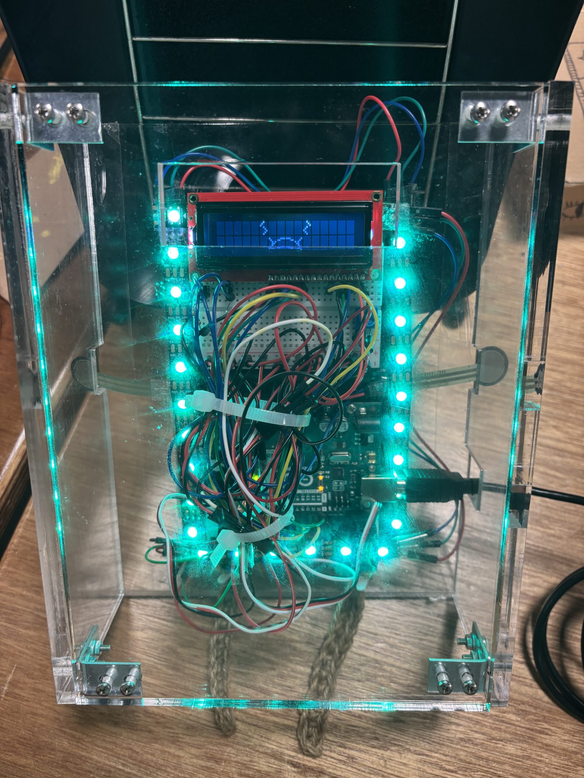
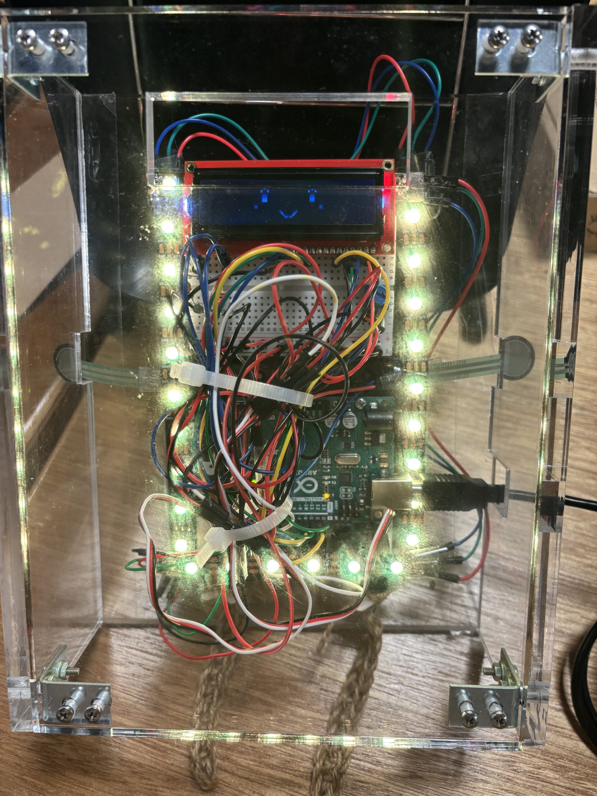
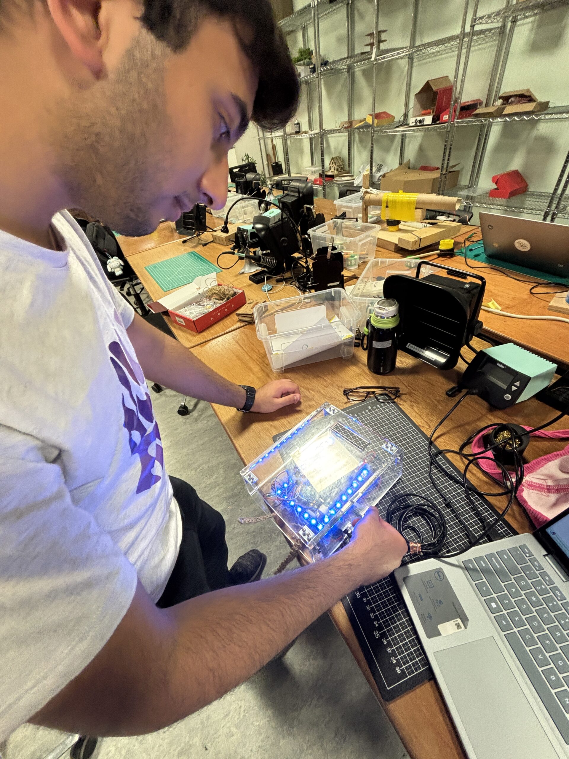
Media (photos)
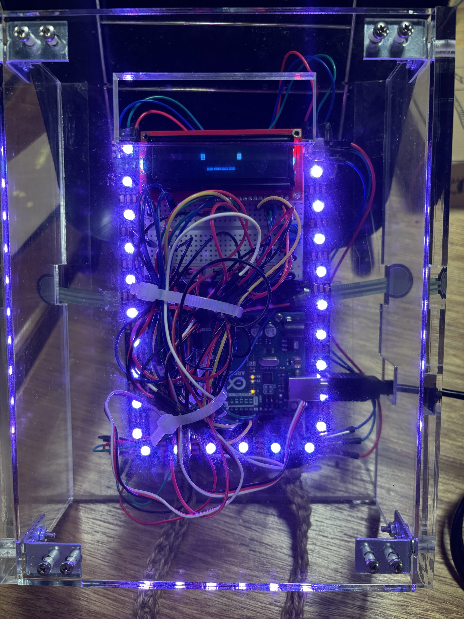
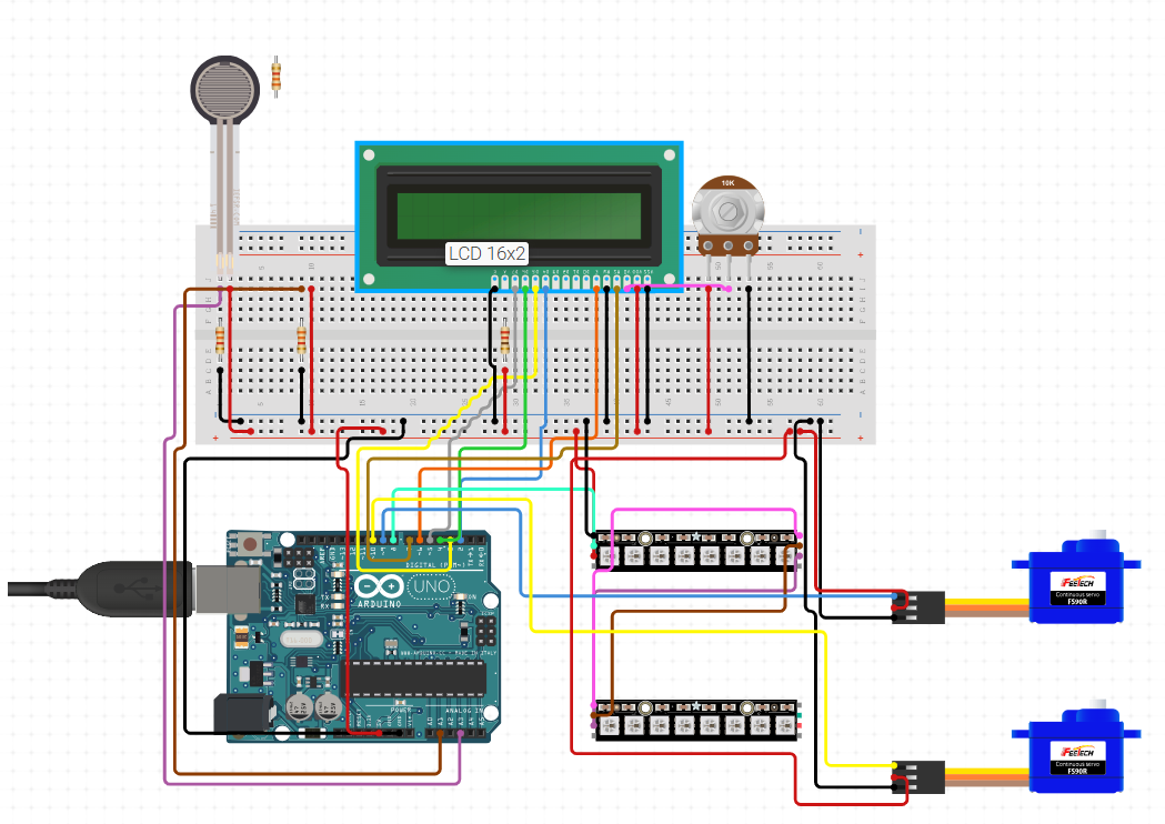
Implementation
Link to sketch: https://editor.p5js.org/bobbybobbb/full/yeMCC3H4B
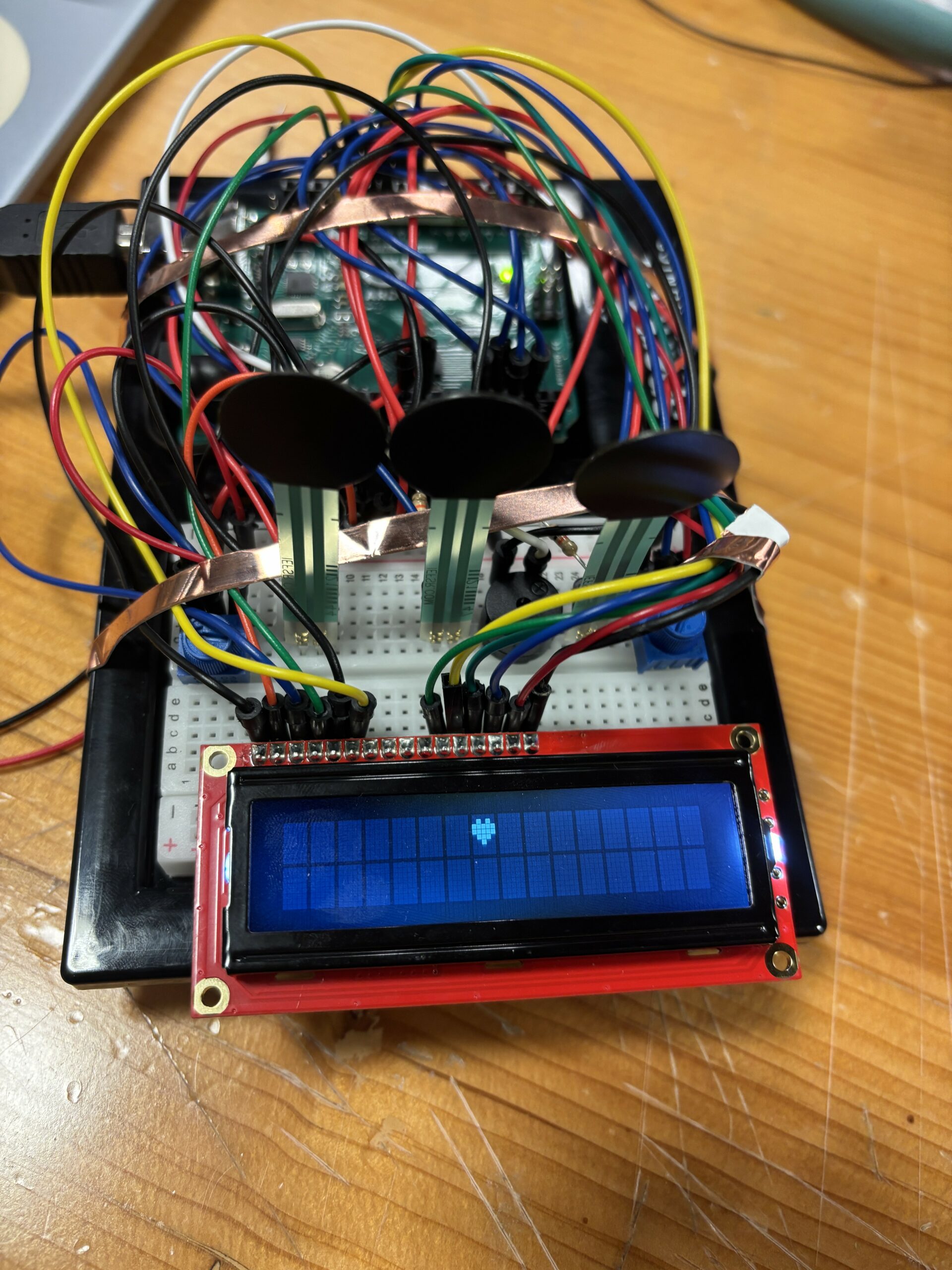
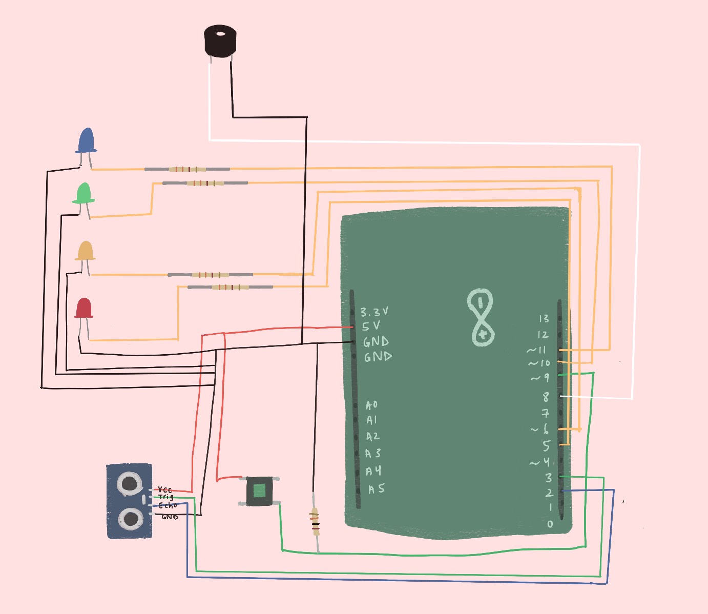
p5 and Arduino are communicating with each other by sending each other values like the emotional state of the robot and FSR values. p5 controls the emotional value (each number represents a different emotion) and sends it to Arduino so that the LCD screen will display the correct facial expression and the LED lights will display the corresponding colors. The emotional state also controls the servo motors that act as the legs. The force sensitive resistor values get sent to p5 to control sadness and happiness since they act as hands being held. Interactions also correspond with specific sounds, which I’m particularly proud of as it adds a lot more atmosphere to the experience. For example, holding hands triggers a specific sound, holding the hands too hard also triggers another sound, feeding the robot triggers another sound, the hunger bar going down triggers a sound, and feeding on a full stomach also triggers a different sound.
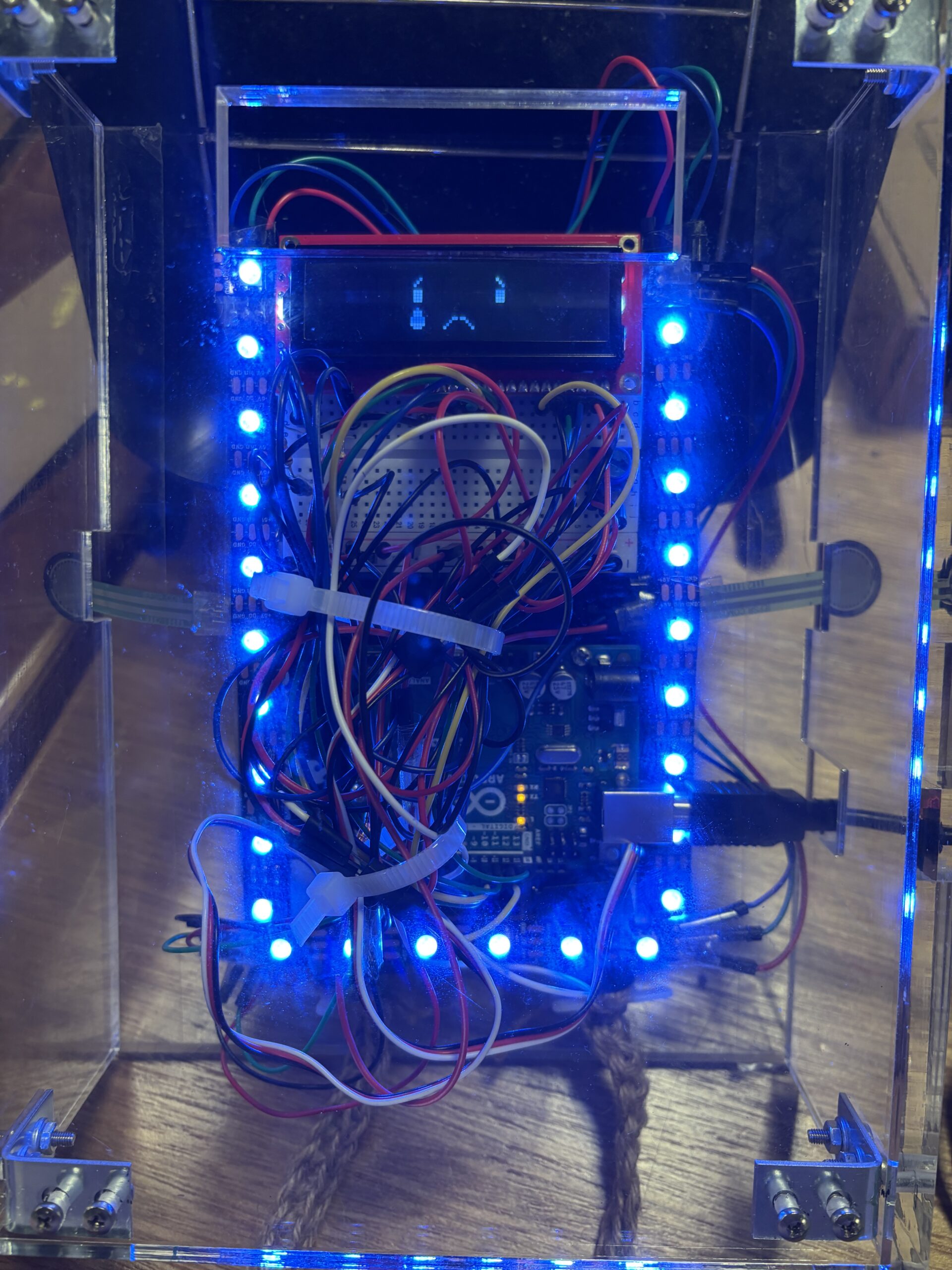
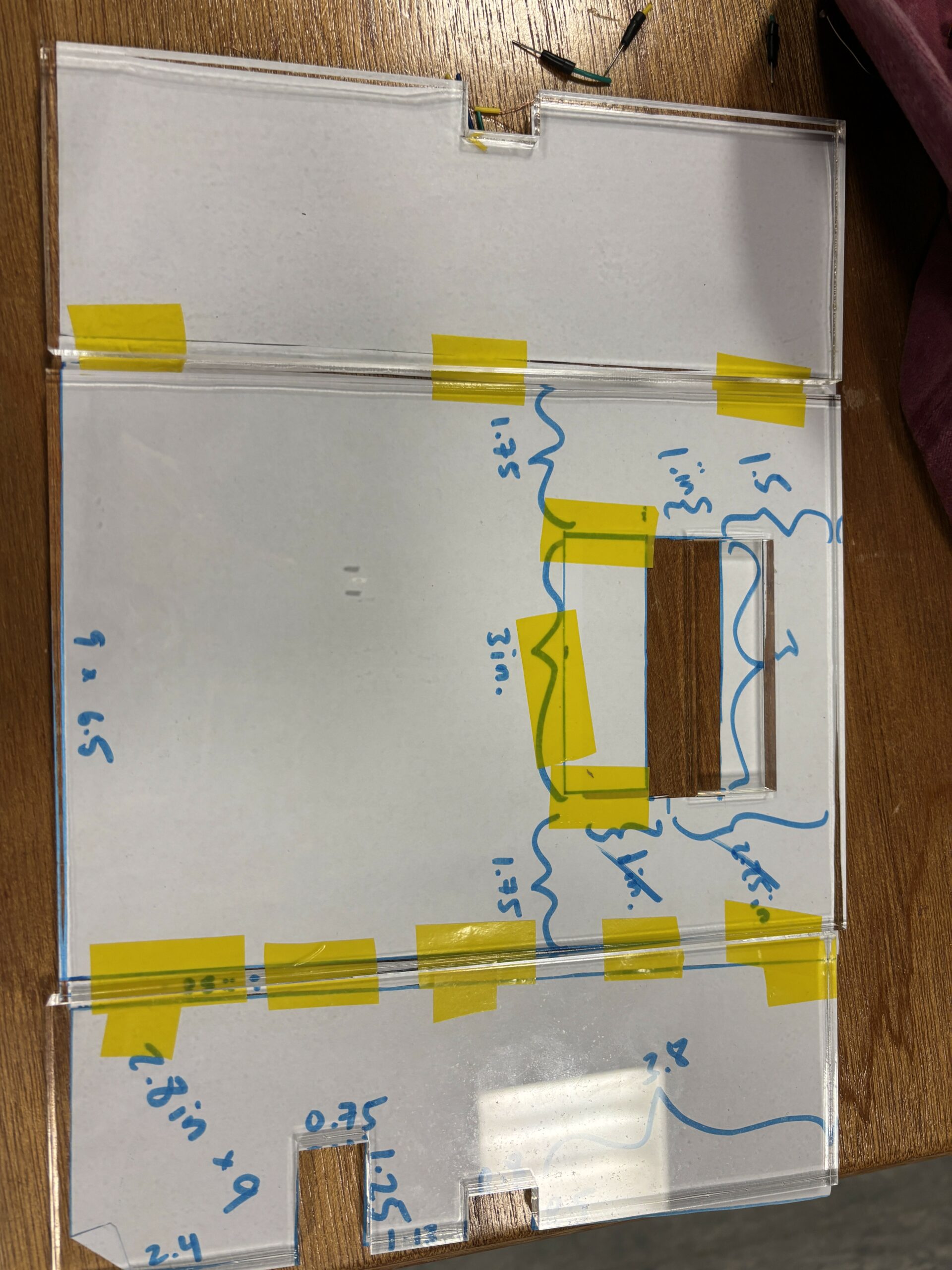
Once I had all my functionality implemented like the code and the circuit, I moved on to beautifying the robot by building a casing for it. The wires and circuit make it hard to make a simple box for the robot, so I had to do a lot of paper-prototyping at first to get the shape and dimensions of casing. By using paper, I could easily cut and paste pieces together to fit across the robot. Even if I made mistakes, the adaptability of paper made it simple to fix. Once I found the right dimensions, I created Illustrator files to laser cut pieces of acrylic out. From there, I needed to drill sides together to create a 3-dimensional box shape.

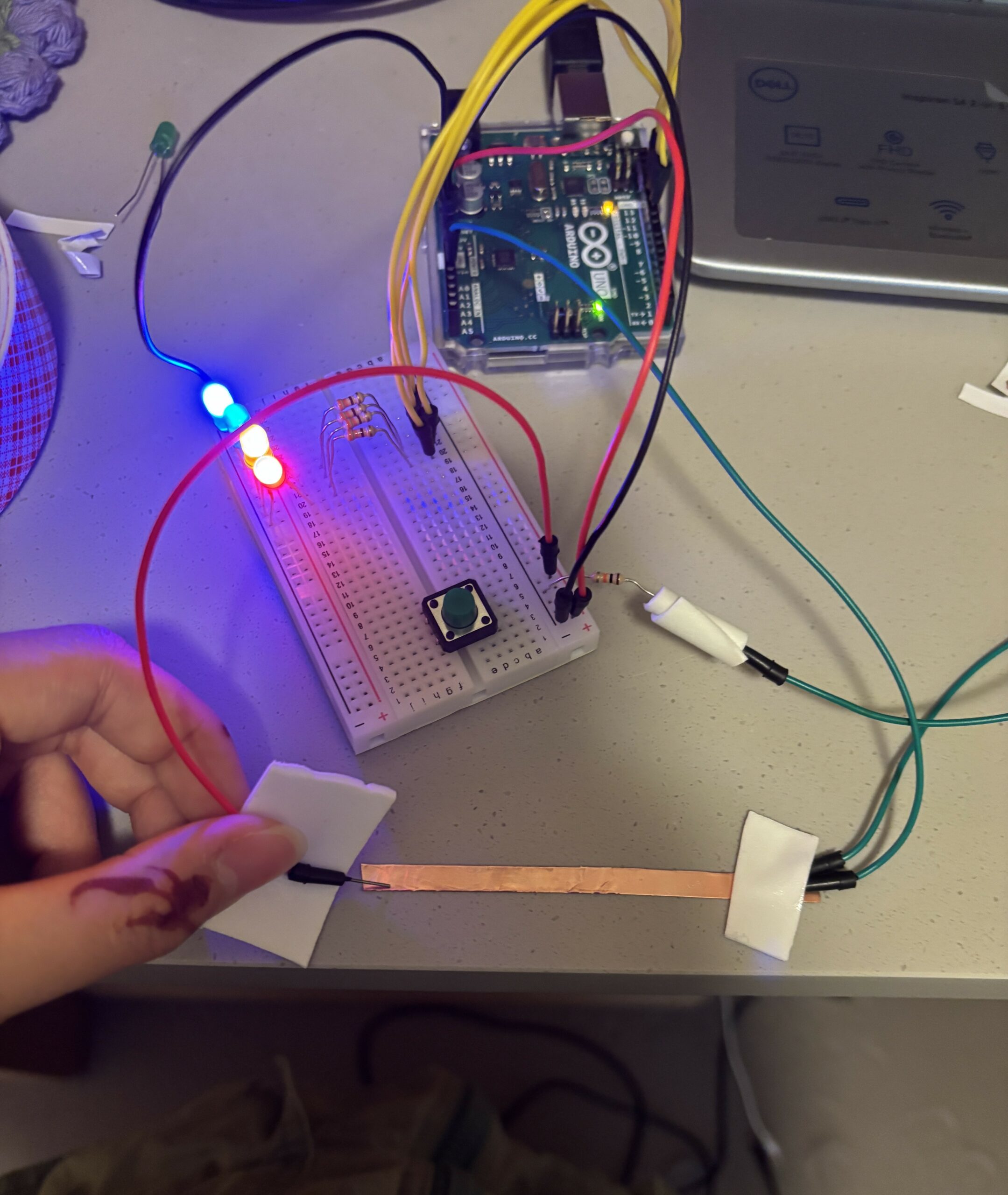
Early prototype: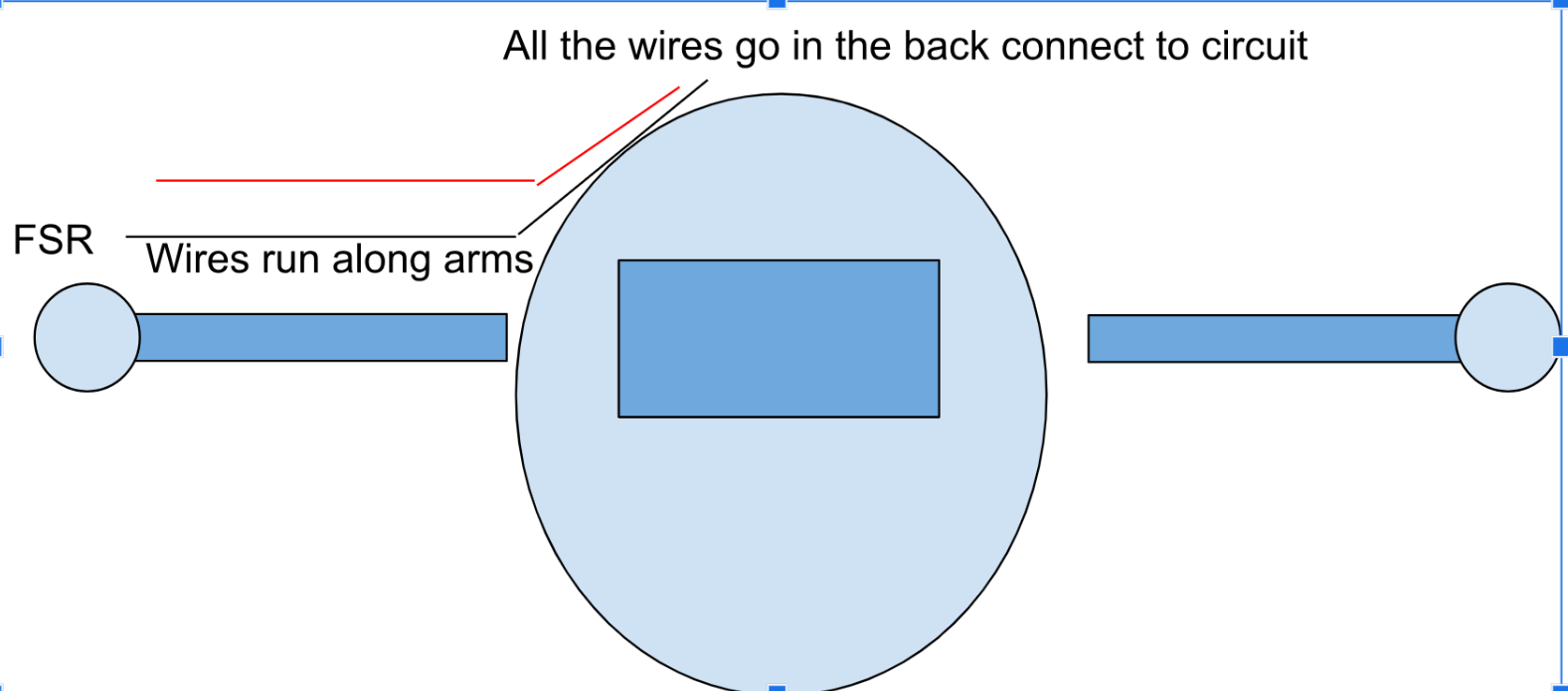
Video of early prototype (Had to make sure all the functionality worked before the visuals came in):
https://drive.google.com/file/d/1RJzqBWGN9Tan1qQ-CqXS2n1jlQ580AKP/view?usp=sharing
User Testing
When user testing, peers commented on the user interface of the p5 sketch and mentioned how it’d be nice if the sketch matched the physical body of the robot better. They also mentioned the awkward holding of the robot (before it was encased). I was at a loss for how to build the casing of the body, and so I asked some of my peers who are more experienced with these kind of things for suggestions. I ended up using the L shaped brackets to help make the box and laser cutting my box out of acrylic under the advice of Sumeed and David, and with the help of IM lab assistants.
Difficulties
Communication between p5 and Arduino was difficult to implement because my computer crashed at some point from the code. I wasn’t sure what I did wrong, so I referred to the example from class, replicated it and changed some values to test out simple functionality at first. Once I made sure Arduino and p5 were communicating in real time, I started building my project from there.
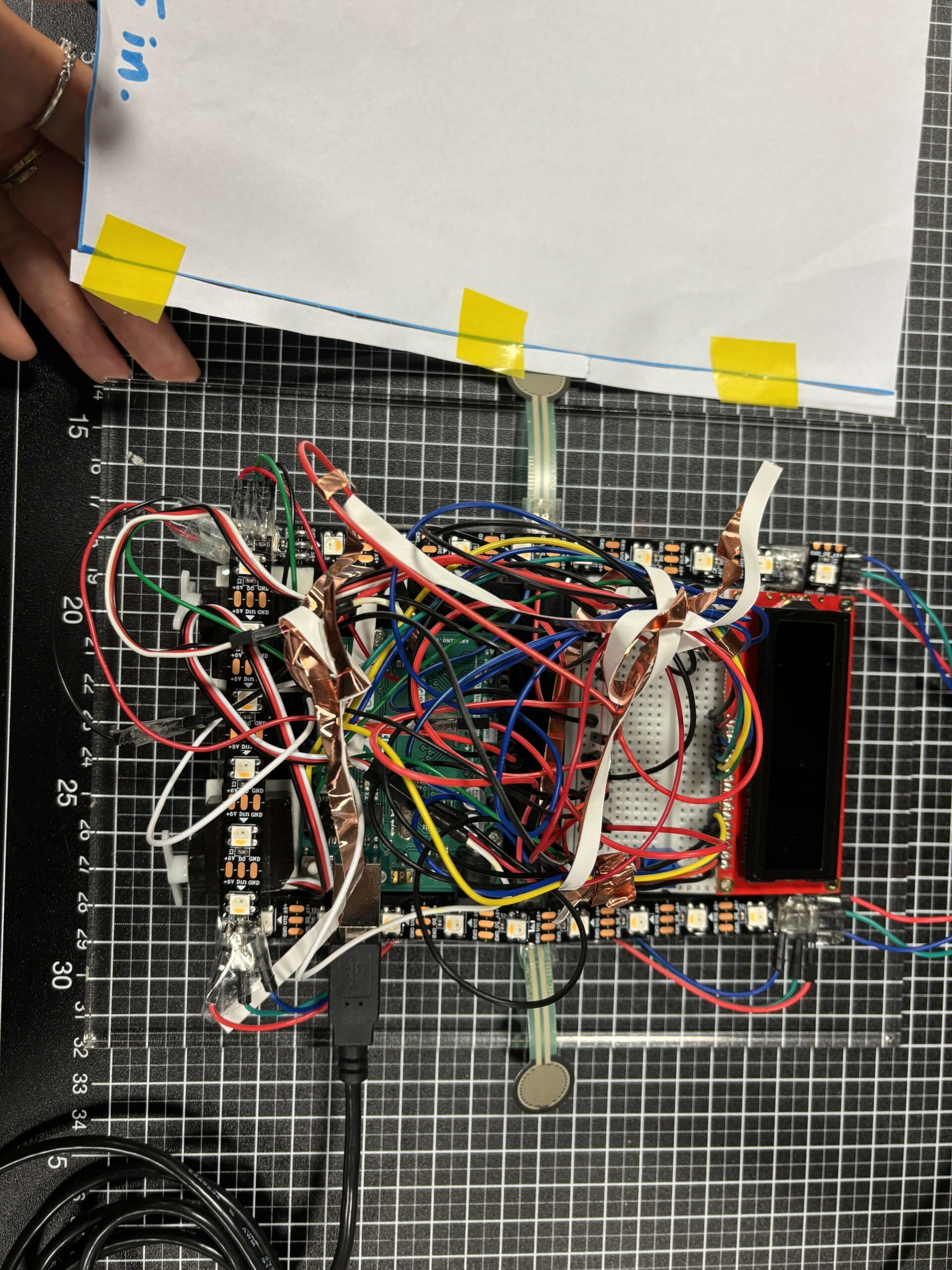
Most of my difficulties came from hardware and building the physical robot since I’m most unfamiliar with hardware compared to software. For example, I wanted the FSR to resemble hands poking out the robot, but upon taping down the FSR, I realized that depending on where you tape the FSR, this’ll affect the sensor readings. There’s also very limited room on the base plate I’m using to hold the Arduino and breadboard for all the wiring involved. For example, I wanted everything to be contained in a neat box, but the Neopixel wires stick out quite a bit. I ended up just making a bigger box to counteract this.
Using Neopixels was a huge part of my project and a must. To use them, I needed to solder wires to the Neopixels, which took a really long time because instead of soldering into a hole, I’m soldering to a flat surface and have to make sure the wires stick on to that flat copper surface. Sometimes, the wires would fall off or it’d just be really difficult to get the wire to stick to the solder on the copper surface. After soldering came the software; I tested using the example strandtest by Adafruit, but it didn’t have the correct outcome even though the lights turned on perfectly. They weren’t displaying the right colors. Mind you, I randomly took these from the IM lab, so I had no idea what type of Neopixels they were. It simply came down to testing out different settings for the different types of Neopixels that exist until I hit the right one.
The LCD screen is also technically upside-down on the robot body because it’s the only way for maximum room on the breadboard to put wires in. Since I had no other option but to put the screen upside down, I had to draw and display all the pixels and bytes upside down. This required a lot of coordination and rewiring my brain’s perspective.
Future Improvements
In the future, I want to use an alternate source of power for the servo motors and Neopixels because every time the servo motors run, the LCD screen blinks and is less bright because the motors take up a lot of power. Every time the Neopixels switch from one color to another, the LCD screen is also affected. I think hooking up a battery to the circuit would solve this problem. In the future, I think more sensors and ways to interact with the robot would also be nice.