Final Project

  1. Concept Description

For my Arduino final project, I made a smart temperature and humidity monitor with a buzzer alarm. This project uses a DHT11 sensor to read the room temperature and humidity. The numbers are shown on a small OLED screen, so the user can clearly see the current condition of the room. When the temperature goes above 32°C, the buzzer will start making sound as a warning. When the temperature goes back below 32°C, the buzzer will stop.

This project is designed for simple everyday use. It could be used in a dorm room, bedroom, classroom, or small workspace. The user does not need to press any buttons or change any settings. They only need to plug in the device, and then it starts working by itself. I wanted the interaction to feel simple and automatic, because the user can understand the information just by looking at the screen and hearing the alarm.

  1. System Diagram & Component Layout

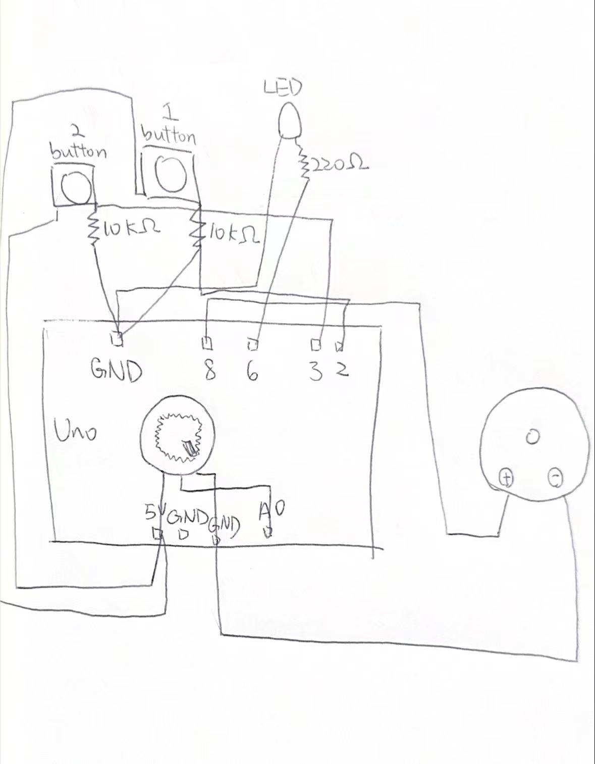
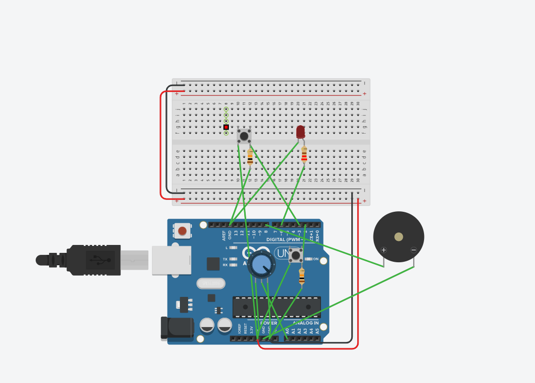
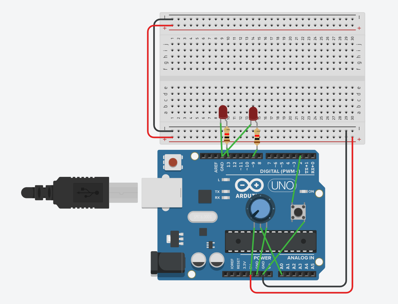
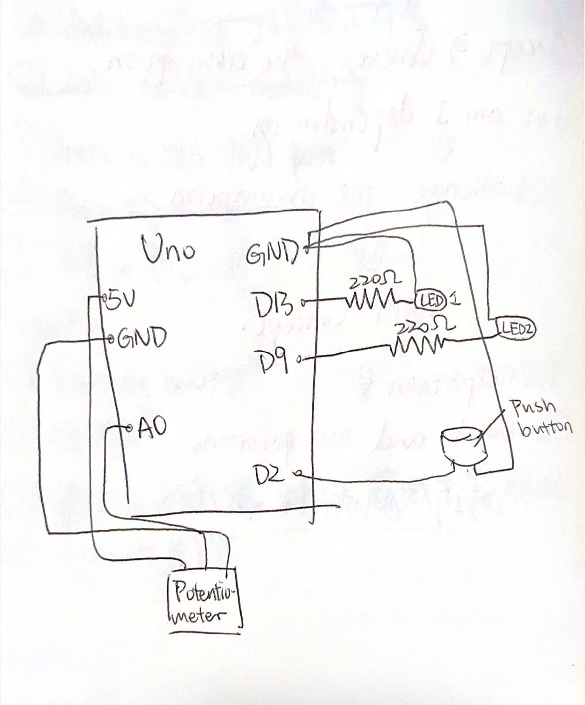
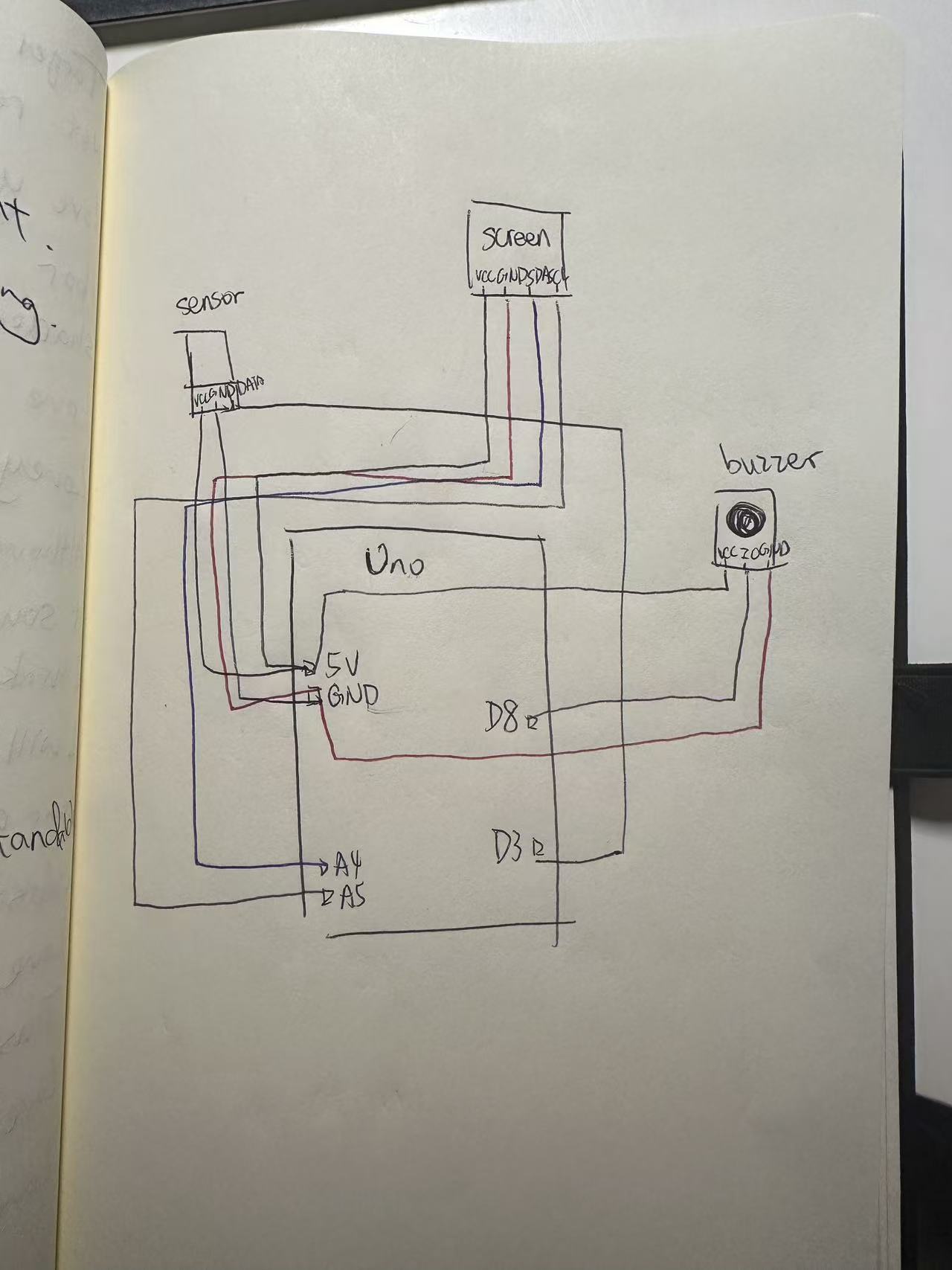
This project uses four main parts: an Arduino UNO board, a DHT11 temperature and humidity sensor, a 128×64 OLED display, and an active buzzer. The Arduino is the main controller. The DHT11 sensor collects temperature and humidity data. The OLED screen shows the data. The buzzer gives sound feedback when the temperature is too high.

3. Vimeo Video

4. How it works

The way this project works is not very complicated. The Arduino keeps reading data from the DHT11 sensor. If the sensor gives a valid temperature and humidity value, the Arduino saves the data and sends it to the OLED screen. The screen then refreshes and shows the newest temperature and humidity numbers.

The program also checks the temperature in every loop. I set the warning temperature to 32°C. If the temperature is below 32°C, the buzzer stays off. If the temperature is higher than 32°C, the Arduino turns on the buzzer. When the temperature drops again, the buzzer turns off automatically.

I had to fix the code several times. One problem was that the buzzer kept making sound even when the temperature was not high enough. Another problem was that the OLED screen stopped showing after a few seconds. I changed the code so the buzzer can turn on and off correctly, and I also added settings to make the OLED screen more stable.

I learned how to build this project from different resources. I watched YouTube videos to understand how the DHT11 sensor and OLED screen work. I also used online courses from the store where I bought my Arduino kit. The store also gave me a beginner Arduino book, and I used that book to understand the basic wiring, pins, and code structure. These resources helped me a lot because I am still learning Arduino and physical computing. I wrote the code in the first place, however, I founf it a bit messy, so I put them in to AI to oragnize and be more clear. Since I wrote some code about the sensor, however it is conflicted to the screen. And I tried to fix it by asking GPT.

#include <Wire.h>
#include <Adafruit_GFX.h>
#include <Adafruit_SSD1306.h>
#include <DHT.h>

#define SCREEN_WIDTH 128
#define SCREEN_HEIGHT 64

#define DHTPIN     3
#define DHTTYPE    DHT11
#define BEEP       8

Adafruit_SSD1306 display(SCREEN_WIDTH, SCREEN_HEIGHT, &Wire, -1);
DHT dht(DHTPIN, DHTTYPE);

float temp = 25.0;
float humi = 50.0;

void setup() {
  Serial.begin(9600);

  Wire.begin();
  Wire.setClock(100000);   // Slower I2C speed, more stable for OLED

  dht.begin();

  pinMode(BEEP, OUTPUT);

  // Active-LOW buzzer: HIGH = OFF, LOW = ON
  digitalWrite(BEEP, HIGH);

  // Start OLED
  if (!display.begin(SSD1306_SWITCHCAPVCC, 0x3C)) {
    Serial.println("OLED failed to start");
    while (true); // Stop here if screen is not found
  }

  display.clearDisplay();
  display.setTextSize(1);
  display.setTextColor(SSD1306_WHITE);
  display.setCursor(5, 10);
  display.println("System Starting...");
  display.display();

  delay(1000);
}

void loop() {
  // Keep OLED awake
  display.ssd1306_command(SSD1306_DISPLAYON);

  float t = dht.readTemperature(); // Celsius
  float h = dht.readHumidity();

  if (!isnan(t)) {
    temp = t;
  }

  if (!isnan(h)) {
    humi = h;
  }

  Serial.print("Temp: ");
  Serial.print(temp);
  Serial.print(" C   Humi: ");
  Serial.print(humi);
  Serial.println(" %");

  display.clearDisplay();

  display.setTextSize(1);
  display.setTextColor(SSD1306_WHITE);

  display.setCursor(5, 5);
  display.println("DHT11 Monitor");

  display.setCursor(5, 25);
  display.print("Temp: ");
  display.print(temp, 1);
  display.println(" C");

  display.setCursor(5, 45);
  display.print("Humi: ");
  display.print(humi, 1);
  display.println(" %");

  display.display();

  // Temperature warning
  if (temp >= 32.0) {
    digitalWrite(BEEP, LOW);    // buzzer ON
  } else {
    digitalWrite(BEEP, HIGH);   // buzzer OFF
  }

  delay(2000);
}

5. Reflection

At the beginning, this project was much harder than I expected. The OLED screen did not show anything at first. After searching on Google, I learned that I needed to download the correct libraries, like Adafruit SSD1306 and Adafruit GFX. After installing them and changing the code, the screen finally worked.

Then I had problems with the DHT11 sensor. At first, I thought the sensor was broken because it could not read temperature or humidity. I watched YouTube videos, took photos of my circuit, and asked AI for help. Later, I found a test code on a Chinese website to check the sensor. After uploading it, I found out the sensor was not broken. The real problem was my code. I had written the wrong sensor type, so Arduino could not read it correctly.

The buzzer also did not work well at first. The breadboard connection was unstable, so I changed many wires before it worked. Most of my code came from the Arduino tutorial book from the kit, and I also learned from YouTube videos and online courses from the store where I bought the Arduino. When I got stuck, I asked AI to help me find the problem. This project taught me that Arduino work needs patience, testing, and debugging step by step.

Final Project feedback and progress

I asked my parents to try my Arduino project without giving them any prompts or instructions at first, to see if they could understand how to use it by themselves.
At the beginning, they could not figure out what the project was or what they needed to do. They did not know they needed to clap to trigger the LED light effect. They were confused about the relationship between the sound sensor and the changing lights. There was no clear visual clue to tell them what action would make the project work, so they did not understand the mapping between their behaviour and the project’s reaction.
Even though they did not understand it at first, they thought the project was new, interesting and fun after I showed them how it worked. The part that worked well was the light reaction: once they clapped, the LED changed colour immediately, and they could easily see the interactive effect clearly.
The main parts I had to explain to them were what the project was for and what action they needed to take to trigger the lights. To make it clearer for first-time users, I want to improve the project in two main ways.
First, I will improve the physical packaging and appearance of my project, so it looks more complete and clearer to understand at a glance. Second, I want to make the project functions more complex and more entertaining, so the interaction is more fun for users.
One important reason why my project is still simple is that my real Arduino board only arrived recently. Before this, I only practiced on Tinkercad. I found that virtual simulation on Tinkercad is very different from using real Arduino hardware, so I needed extra time to adapt and test the actual circuits and code. In the next steps, I will continue to upgrade my project to make the overall experience more interesting and interactive.
https://vimeo.com/1189334984

Final Proposal

1. Finalized concept for the project

My project is a simple Arduino interactive LED indicator system. I will use an Arduino board, sound sensor and regular LED lights to make a basic interactive device. When the sound sensor detects clapping or loud noise, the LED will turn on, flash or change state; when it is quiet, the LED will turn off automatically. The whole idea is beginner-friendly, no complex game logic, just basic sensor input and LED output control, suitable for a freshman Arduino practice project.

2. Design and description of Arduino program function
  1. Read real-time signal value from the sound sensor.
  2. Set a simple sound threshold: if the detected sound is louder than the threshold, the program will turn on the LED and let it blink several times.
  3. If there is no loud sound for a few seconds, the LED will turn off and stay in standby mode.
  4. The program runs in a loop all the time, continuously detecting sound and controlling the LED reaction.
3. Overall project work & progress documentation
  1. First, I confirmed my project idea, chose sound sensor + LED as the main hardware, decided to make a simple sound-activated light.
  2. I prepared all components: Arduino UNO, sound sensor, LED, resistor, jumper wires and breadboard.
  3. I learned basic Arduino wiring rules and finished circuit connection step by step.
  4. I started to write simple test code, upload to Arduino, and test if the sensor and LED work normally.
  5. I adjusted the sound threshold value many times to make the sensor respond stably to clapping sound.
  6. Now I am optimizing the code to make the LED blink smoothly and the standby mode work correctly.
4. Most challenging part + small demo
The most challenging and unknown part for me is how to correctly read the sound sensor value and set a stable threshold, and make sure the sensor only reacts to claps instead of background noise. I am not familiar with analog sensor reading at first.
I made a small separate demo: I only connect the sound sensor and use a simple demo code to print sensor data to the Serial Monitor. I clap near the sensor many times to observe the value change, then find a suitable number as my threshold. This small demo lets me understand how the sound sensor works and solves the hardest part of my project.
Reference Resources
  1. Arduino Official Documentation: https://www.arduino.cc/en/Reference
  2. Arduino Sound Sensor Tutorial (YouTube & Instructables)
  3. Instructables Basic Arduino Sensor Projects: https://www.instructables.com/circuits/arduino/
  4. W3Schools Arduino Basic Syntax Learning
  5. Course lecture slides and in-class Arduino basic example codes
  6. AI for inspiration and some coding thing
  7. The book that the store gave me when I bought Arduino

Reading reflection

I think this article is really interesting because it shows disability design in a different way. Before reading it, I thought disability design was mostly about helping people move, hear, see, or live more easily. But this article shows that design is also about beauty, identity, and confidence.

One idea I found important is that disabled people should not always have to hide their disability. For example, glasses used to be seen as medical objects, but now many people wear them as fashion. So I wonder why hearing aids, prosthetic legs, or wheelchairs cannot also be designed in a stylish way.

This article also makes me think that “normal” should not always be the final goal. A good design does not need to make everyone look the same. Instead, it can help people feel comfortable and proud of who they are.

My question is: how can designers create products that are both useful and beautiful, while also giving disabled people the choice of how they want to present themselves?

Week 11 Assignment

Concept

The concept of my project is to create a simple electronic musical instrument using Arduino. I wanted to turn basic components like a button and a potentiometer into something interactive and expressive. The button works like a “play key,” while the potentiometer controls the pitch of the sound. By combining these elements, the user can actively “play” the instrument instead of just hearing a fixed sound. I also added a second button to switch between low and high pitch modes, which makes the instrument feel more dynamic and closer to a real musical device.

How I Made This

int playButtonPin = 2;
int modeButtonPin = 3;
int buzzerPin = 8;
int ledPin = 6;
int potPin = A0;

int lowNotes[]  = {262, 294, 330, 349, 392, 440, 494, 523};   // C4 到 C5
int highNotes[] = {523, 587, 659, 698, 784, 880, 988, 1047};  // C5 到 C6

bool highMode = false;
int lastModeButtonState = LOW;

void setup() {
  pinMode(playButtonPin, INPUT);
  pinMode(modeButtonPin, INPUT);
  pinMode(buzzerPin, OUTPUT);
  pinMode(ledPin, OUTPUT);
  Serial.begin(9600);
}

void loop() {
  int playButtonState = digitalRead(playButtonPin);
  int modeButtonState = digitalRead(modeButtonPin);
  int potValue = analogRead(potPin);

  int noteIndex = map(potValue, 0, 1023, 0, 7);

  // detect second button:change mode
  if (modeButtonState == HIGH && lastModeButtonState == LOW) {
    highMode = !highMode;
    delay(200); // 
  }
  lastModeButtonState = modeButtonState;

  int frequency;
  if (highMode) {
    frequency = highNotes[noteIndex];
  } else {
    frequency = lowNotes[noteIndex];
  }

  if (playButtonState == HIGH) {
    tone(buzzerPin, frequency);
    digitalWrite(ledPin, HIGH);
  } else {
    noTone(buzzerPin);
    digitalWrite(ledPin, LOW);
  }

  Serial.print("Mode: ");
  if (highMode) {
    Serial.print("HIGH");
  } else {
    Serial.print("LOW");
  }

  Serial.print("  Note index: ");
  Serial.print(noteIndex);
  Serial.print("  Frequency: ");
  Serial.println(frequency);

  delay(10);
}


I started by building a very basic circuit with a buzzer, a button, and a potentiometer. At first, the buzzer only made continuous sounds, which didnot feel like music. Then I modified the code so that the potentiometer controls discrete notes instead of continuous frequencies. This made the sound more like a real scale (Do, Re, Mi).

After that, I added a second button to switch between two sets of notes (low and high pitch). This required both wiring changes and updating the code logic to detect button presses and toggle modes. I also added an LED that lights up when the instrument is being played, which gives visual feedback and makes the interaction clearer.

Throughout the process, I tested each part step by step instead of building everything at once. This helped me identify problems more easily and understand how each component works.

What I’m Proud Of

The part I’m most proud of is how I figured out the mistakes with the buttons. At the beginning, my buttons did not work correctly at all. Sometimes the sound would play randomly, and sometimes pressing the button did nothing. I realized later that I misunderstood how the button pins (1A, 2A, etc.) are connected internally, and I also forgot to use the resistor properly.

After debugging, I learned that the button needs to cross the middle gap on the breadboard and that I must connect a pull-down resistor to stabilize the signal. Fixing this problem made everything work correctly, and it was a moment where I felt I really understood the circuit instead of just following instructions. This experience helped me become more confident in troubleshooting hardware problems.

What I Can Do Better Next Time

Next time, I think I can improve both the design and the interaction of my project. Right now, the instrument is still quite simple, and the sound is limited to basic tones. I could improve this by adding more buttons to create a small keyboard or by programming simple melodies.

I also want to make the interaction more intuitive. For example, I could use a light sensor to control pitch instead of a potentiometer, which would make the instrument feel more creative and less mechanical. Another improvement would be organizing the wiring more clearly, because my current circuit is a bit messy and hard to read.

Overall, this project helped me understand both coding and circuit design better, but I think there is still a lot of space to make it more expressive and closer to a real musical instrument.

Reading reflection

After reading both the essay and the responses, one clear idea is the difference between what interaction design could be vs what it is now. Bret Victor wants computers to help people think and understand, not just click buttons. This made me reflect that many of my own projects are still very basic—more like reactions, not real thinking tools.

Another important thought is about making things visible. He argues that systems should show how they work instead of hiding everything. This connects to learning. When I can see changes directly, I understand faster. So interaction design is not only about design, but also about how people learn.

However, the responses made me question his ideas. Some people say his vision is too idealistic and hard to apply in real life. Real systems have limits, and not all users want to explore deeply. Sometimes people just want things to be fast and simple. So his ideas may work better for learning tools, not everyday apps.

It also made me think about the role of the designer. Instead of controlling everything, the designer creates a system where users explore by themselves. This is similar to interactive art, but it also means less control over the final experience.

Overall, these readings made me see interaction design as more than coding. It is about how people think, understand, and interact with systems, but also about balancing ideal ideas with real-world limits.

Week 10 Assignment

Concept

My project is a simple interactive lighting system using one analog sensor and one digital sensor. I used a potentiometer as the analog sensor and a pushbutton as the digital sensor. The idea is that the potentiometer controls the brightness of one LED, while the button controls whether the other LED turns on or off. I wanted to make a small circuit that shows two different ways Arduino can read input and control output. This project is simple, one LED changes gradually, while the other only has two states, on and off.

How I made it:

const int potPin = A0;      // potentiometer connected to analog pin A0
const int buttonPin = 2;    // pushbutton connected to digital pin 2
const int ledDigital = 13;  // LED controlled by the button
const int ledAnalog = 9;    // LED with adjustable brightness

void setup() {
  pinMode(buttonPin, INPUT_PULLUP);  // use the internal pull-up resistor for the button
  pinMode(ledDigital, OUTPUT);       // set digital LED as output
  pinMode(ledAnalog, OUTPUT);        // set analog LED as output
}

void loop() {
  // read the potentiometer value from 0 to 1023
  int potValue = analogRead(potPin);

  // convert the potentiometer value into a brightness value from 0 to 255
  int brightness = map(potValue, 0, 1023, 0, 255);

  // control the brightness of the LED on pin 9
  analogWrite(ledAnalog, brightness);

  // read the button state
  int buttonState = digitalRead(buttonPin);

  // when the button is pressed, turn on the digital LED
  // when the button is not pressed, turn it off
  if (buttonState == LOW) {
    digitalWrite(ledDigital, HIGH);
  } else {
    digitalWrite(ledDigital, LOW);
  }
}

First, I built the circuit in Tinkercad because I do not have a physical Arduino with me right now. I added an Arduino Uno, a potentiometer, a pushbutton, two LEDs, and resistors. Then I connected the potentiometer to 5V, GND, and A0 so Arduino could read its analog value. After that, I connected the pushbutton to pin 2 and GND so it could work as a digital input.

Next, I connected one LED to pin 13 for simple on and off control, and another LED to pin 9 so I could control its brightness with PWM. In the code, I used analogRead() to read the potentiometer value and map() to change that value into a brightness level from 0 to 255. Then I used analogWrite() to change the brightness of the LED on pin 9. For the button, I used digitalRead() to check whether it was pressed, and then I turned the LED on pin 13 on or off.


What I’m proud of

I am proud that I solved a problem by checking my circuit carefully. At the beginning, I placed the button incorrectly, so LED2 could not light up. At first, I thought the code might be wrong, but later I realized the problem was in the button connection. After fixing the button placement, the circuit worked correctly.

This mistake helped me learn that in Arduino projects, the wiring is just as important as the code. Even if the code is correct, the circuit will not work if one part is connected incorrectly. I think this was an important learning moment for mebecause I am still new to Arduino.

Conclusion

Overall, this project helped me understand the basic difference between analog input and digital input. I learned how a potentiometer can control LED brightness and how a pushbutton can control an LED in a simple on/off way. I also learned how important it is to test carefully and fix mistakes step by step. However, this is my very fist time to learn Arduino, so this project might be a bit lack of creativity. But during the process, I learned the basics of Arduino.

Reading reflection and thoughts

One thought is that this article changes the role of the artist. Usually, we think the artist’s job is to express a clear message. But in this reading, the artist is more like a designer of experience. The artist builds the situation, and the audience helps finish the work through their actions.

Another idea is that interactive art is not fully complete until people engage with it. This makes the artwork feel alive and open, not fixed like a painting with one meaning. I think this is interesting because it gives more power to the audience.

I also thought about the phrase “set the stage, then shut up.” It sounds strong, but the meaning is important. The artist should guide people through space, objects, and hints, but should not explain too much. Too much explanation can limit people’s feelings and reactions.

The article also made me think that misunderstanding is not always failure. If people use the work in unexpected ways, that can still be part of the conversation. Their confusion or surprise may reveal something important about the design.

Another idea is that interactive art needs good affordance. If you want people to touch something, the object should invite touch. If you do not want touch, it should not look touchable. So meaning is not only in words, but also in design, placement, and behavior.

I also thought this reading connects interactive art to performance. The audience is not just watching; they are acting. This makes the artwork closer to theatre or rehearsal, where meaning is discovered through action, not just given in advance.

Week 9 reading


Reading 1(longer one):

One idea I got from the reading is that beauty is not just decoration. Attractive design can actually change how people feel, and that feeling can affect how well they use something.

I also thought it was interesting that people do not always choose things only because they are the most efficient. Sometimes we choose objects because they feel enjoyable, elegant, or comforting. That makes design feel more human, not just technical.

Another idea is that emotion affects thinking. When people feel relaxed and positive, they may become more open, creative, and flexible. But when they feel stressed, they focus more narrowly. This made me think that design should match the situation people are in.

The reading also made me think that usability and aesthetics should not be separated too much. A product may work well in a mechanical sense, but if it feels unpleasant, the whole experience is weaker. Good design should care about both function and feeling.


Reading 2(shorter one):

Margaret Hamilton did more than write programs. She helped make software into a serious field. At first, software was not even treated as an important part of the Apollo mission, but later it became central to success.

I also think the article has a strong message about responsibility. Hamilton understood that small mistakes in code could become huge real-life dangers. That makes her work feel very modern, because today we still depend on software in high-stakes situations.

The article also suggests that great inventions are not only about one person. Hamilton was a major leader, but Apollo software was built by a large team, including many women whose work is often forgotten. That makes the article partly about hidden labor and recognition.

Midterm Project: Where is the ghost?

Concept 
This project is a small “ghost hunting” camera game inspired by Identity V. In Identity V, a detective enters a mysterious place and slowly discovers clues. I borrowed that detective-in-a-secret-castle feeling and turned it into an interactive p5.js experience. The player is a brave “ghost catcher” who explores an ancient castle at night, hears strange whispers, and tries to help the people living there by collecting evidence.

I also wanted to change the usual mood of ghosts. Ghosts don’t always have to be terrifying. In my game, the ghosts are faint and mysterious in the live scene, but when you successfully capture one in a photo, it becomes cute and playful (with a tongue-out expression). I like this because it matches how cameras work in real life: people often want to look “better” in front of the camera, and the photo becomes a different version of reality.

How the project works + what I’m proud of 
The game starts on an instruction screen with a short story setup, then waits for the player to press a key or click a start button. During gameplay, the mouse controls a flashlight that reveals the scene. Ghosts appear only sometimes, and they are only visible when they are inside the flashlight area. To “capture” a ghost, the player takes a photo (click or space) while a ghost is inside the light. The photo preview shows the captured frame like a polaroid, and if a ghost was caught, it displays a special “cute ghost” version. The game ends when the player captures enough ghosts, runs out of time, or runs out of film, and then it offers a restart without refreshing.

I separated “live view” from “photo view.” In the live scene, ghosts only count if they are currently visible AND inside the flashlight radius (so the player must aim and time it). Then, after a successful capture, I draw a special “tongue ghost” onto the captured image buffer (photoImage). This makes the camera feel meaningful: it doesn’t just add score, it changes the ghost’s personality in the “photo reality,” matching my concept that people want to look better on camera.

let capturedGhost = null;
for (let g of ghosts) {
  if (g.isVisibleNow() && g.isInsideFlashlight(mouseX, mouseY)) {
    capturedGhost = g;
    break;
  }
}

Then I did the important trick: I made a separate “photo layer” instead of drawing everything directly on the main screen. I create a new graphics canvas for the photo, and I copy the current screen into it. That’s what makes the photo feel like it’s frozen in time:

photoImage = createGraphics(width, height);
photoImage.image(get(), 0, 0);

After that, if I really did capture a ghost, I draw the cute tongue ghost onto the photo layer (not the live game). And I add to my capture count:

capturedGhost.drawTongueStrongOn(photoImage);
ghostsCaptured++;

Once I got this working, the whole game started to make sense. The live view stays spooky and subtle, but the photo becomes the “evidence,” and the ghost looks cuter in the picture—kind of like how people also want to look better when a camera points at them.

Areas for improvement + problems I ran into 
One area to improve is balancing and clarity. Sometimes players may miss ghosts too easily, depending on timing and where the flashlight is. I want to tune the ghost visibility timing and the capture conditions so it feels fair but still challenging. I also want to add clearer feedback when a ghost is nearby so the player can learn the game faster.

Adding sound was harder than I expected because browsers don’t just let a game play audio whenever it wants. In p5.js, if you try to play sound automatically when the page loads, most browsers will block it. They only allow audio after a real user action, like a click or pressing a key. At first this felt confusing, because my code was “correct,” but nothing played. So the challenge wasn’t only choosing sounds—it was designing the game flow so sound is unlocked in a clean way.

To fix that, I made sure audio starts only after the player begins the game on purpose. When the player presses SPACE (or clicks START), I call my audio setup function ensureAudioStarted(). Inside that function I use userStartAudio() (from p5.sound) to unlock audio, then I start my sound sources (an oscillator and a noise generator) at zero volume so they’re ready but not making noise.