
-
-
- Describe your concept
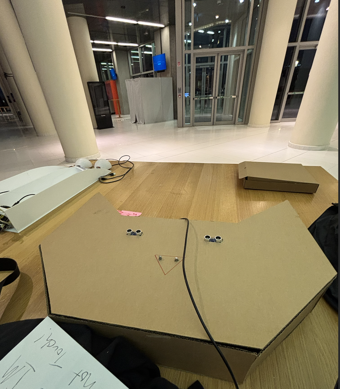
- My concept is a musical controller. With the inputted song, users can use potentiometers and proximity sensors to control different aspects of the sound such as reverb and delay. On the p5 end, there is a spectral music visualizer where you can see the volume of each band (section of frequencies) across the sketch. There is also a sound visualizer cat, modelled after my arduino cat, that moves with the music.
- Include some pictures / video of your project interaction
- How does the implementation work?
-
- Description of interaction design
- The user moves their hand over the sensors to control reverb and delay, and distortion in the sound . The knobs can be used to manipulate pitch and filter of the sound
- Description of Arduino code and include or link to full Arduino sketch
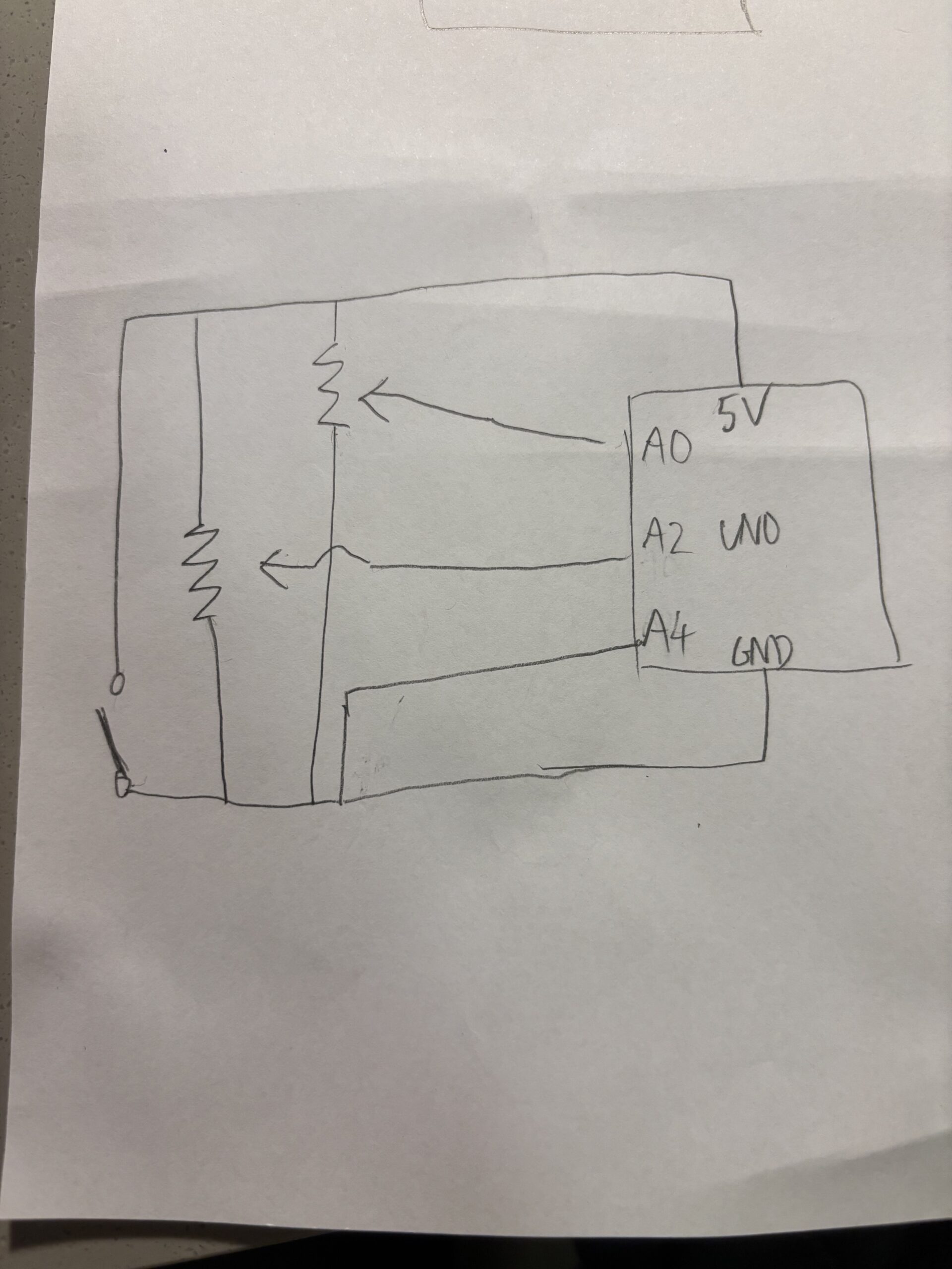
/* * created by Rui Santos, https://randomnerdtutorials.com * * Complete Guide for Ultrasonic Sensor HC-SR04 * Ultrasonic sensor Pins: VCC: +5VDC Trig : Trigger (INPUT) - Pin11 Echo: Echo (OUTPUT) - Pin 12 GND: GND */ int potPinA = A1; int potPinB = A2; int trigPinA = 8; // Trigger int echoPinA = 9; // Echo int trigPinB = 10; // Trigger int echoPinB = 11; // Echo int potValA; int potValB; int prevSenValA; int prevSenValB; long durationA; long durationB; long cma, cmb, inches; void setup() { //Serial Port begin Serial.begin (9600); //Define inputs and outputs pinMode(potPinA,INPUT); pinMode(potPinB,INPUT); pinMode(trigPinA, OUTPUT); pinMode(echoPinA, INPUT); pinMode(trigPinB, OUTPUT); pinMode(echoPinB, INPUT); } void loop() { // The sensor is triggered by a HIGH pulse of 10 or more microseconds. // Give a short LOW pulse beforehand to ensure a clean HIGH pulse: digitalWrite(trigPinA, LOW); delayMicroseconds(5); digitalWrite(trigPinA, HIGH); delayMicroseconds(10); digitalWrite(trigPinA, LOW); potValA = analogRead(potPinA); potValB = analogRead(potPinB); // Read the signal from the sensor: a HIGH pulse whose // duration is the time (in microseconds) from the sending // of the ping to the reception of its echo off of an object. pinMode(echoPinA, INPUT); durationA = pulseInLong(echoPinA, HIGH); digitalWrite(trigPinB, LOW); delayMicroseconds(5); digitalWrite(trigPinB, HIGH); delayMicroseconds(10); digitalWrite(trigPinB, LOW); pinMode(echoPinB, INPUT); durationB = pulseInLong(echoPinB, HIGH); // Convert the time into a distance cma = (durationA/2) / 29.1; cmb = (durationB/2) / 29.1; // Divide by 29.1 or multiply by 0.0343 if(cma < 500) { prevSenValA = cma; } else { cma = prevSenValA; } if(cmb < 500) { prevSenValB = cmb; } else { cmb = prevSenValB; } Serial.print(cmb); Serial.print(", "); Serial.print(cma); Serial.print(", "); Serial.print(potValB); Serial.print(", "); Serial.print(potValA); Serial.println(); delay(50); } - Schematic of your circuit (hand drawn or using tool)
- also here:
- Description of p5.js code and embed p5.js sketch in post
- Description of communication between Arduino and p5.js
-
- Will use serial communication, with arduino outputting a list at interval. it will be in the form of [sensor 1 distance],[sensor 2 distance],[pot 1 value],[pot 2 val]. This list will be picked up by p5.
-
-
- What are some aspects of the project that you’re particularly proud of?
- the shell design and Arduino code. It took me a long time to learn how to use two sensors in succession on the same Arduino. Other than that, I think using the fft to do the spectrum visualizer was something I am proud of.
- What are some areas for future improvement?
- I could definitely have more moving components, and more ways to modulate the audio signal. Also, one of the sensors kept malfunctioning, so making the overall structure and making it more stable (acrylic box or something) to make it a proper music device. Next time too, make my music thing be able to pick diffferent songs
- Describe your concept
-
Author: Morris Chang

Week 13 – User Testing
Generally, my testing went okay, though because I had not given instructions I think, though, my design was pretty intuitive in such. way I think they got what they were supposed to do. Because my project had to do with modulating sound, the feedback is pretty instantaneous, and because there was not objective, really, users could just mess around with what you can do and really quickly get the hang of it. I am still working on adding an instructions screen on p5, though. I think an easy instructions page would provide all the information people will need to do with my project, just explaining what the different controllers on my cat thing do to the sound.
Week 12 – Project Proposal
This requires some explanation:
Originally, I had a well-fleshed-out idea for the use of motion sensors to play a volleyball game. While conceptually sound, in practice, the motion sensors just could not cooperate. After a lot of testing with Arduino and its sensors, I realized that the ball would move too quick for the sensors to process properly. Instead, I decided to make a violin.
The main mechanism in charge of producing sound will be a potentiometer, in such a way that when a bowstring is pulled back and forth, the potentiometer dial shall turn. Its analog output will be sent to p5, and detecting the bow’s movement will power a synthesizer to play sound. Next, the violin will have digital output buttons. Holding down buttons will give the arduino digital outputs also sent to p5. In p5, detecting which button is being pressed down will turn into a specific note in the scale. each of the 8 buttons represents one note, forming a full scale. This allows us to get a functional violin.
Week 11 Project Exercises
Exercise 1.1
let port;
let connectBtn;
let baudrate = 9600;
let lastMessage = "";

function setup() {
  createCanvas(400, 400);
  background(220);

  port = createSerial();

  // in setup, we can open ports we have used previously
  // without user interaction

  let usedPorts = usedSerialPorts();
  if (usedPorts.length > 0) {
    port.open(usedPorts[0], baudrate);
  }

  // any other ports can be opened via a dialog after
  // user interaction (see connectBtnClick below)

  connectBtn = createButton("Connect to Arduino");
  connectBtn.position(80, 200);
  connectBtn.mousePressed(connectBtnClick);

}

function draw() {
  background("255");


  // Read from the serial port. This non-blocking function
  // returns the complete line until the character or ""
  let str = port.readUntil("\n");
  if (str.length > 0) {
    // Complete line received
    // console.log(str);
    lastMessage = str;


  }


  // Display the most recent message
  text("Last message: " + lastMessage, 10, height - 20);

  // change button label based on connection status
  if (!port.opened()) {
    connectBtn.html("Connect to Arduino");
  } else {
    connectBtn.html("Disconnect");
  }


  ellipse(lastMessage,10,20,20)
}

function connectBtnClick() {
  if (!port.opened()) {
    port.open("Arduino", baudrate);
  } else {
    port.close();
  }
}
Exercise 1.2
let port;
let connectBtn;
let baudrate = 9600;
function setup() {
  createCanvas(255, 285);
  port = createSerial();
  let usedPorts = usedSerialPorts();
  if (usedPorts.length > 0) {
  port.open(usedPorts[0], baudrate);
 } else {
  connectBtn = createButton("Connect to Serial");
  connectBtn.mousePressed(() => port.open(baudrate));
 }
}
function draw() {
  background(225);
  circle(140,mouseY,25,25):
  let sendtoArduino = String(mouseY) + "\n"
  port.write(sendtoArduino);
}
Exercise 1.3
int led = 5;
void setup() {
  Serial.begin(9600);
}

void loop() {
  if (Serial.available()) {
    int ballState = Serial.parseInt();
    if (ballState == 1) {
      digitalWrite(led, HIGH); // ball on ground
    } else {
      digitalWrite(led, LOW); // ball in air or default
     }
  }
  // read the input pin:
  int potentiometer = analogRead(A1);
  int mappedPotValue = map(potentiometer, 0, 1023, 0, 900);
  // print the value to the serial port.
  Serial.println(mappedPotValue);

  delay(100);
}
Week 11 Reading
In the article, one of the most interesting points made was the how solving these design problems for those with disabilities can benefit everyone by creating better products overall, not just tailored to those with a disability. This really goes against what ideas we would intuitively have about design, creativity and innovation; namely that more is more. But this article argues that working with constraints, in this case, the unique needs of a person with a disablilty, actually leads to more creative outcomes that can branch out into better designs for general use. Namely, the article says working with disabilities in mind pushes designs to be more simple to increase ease of use, to be more discreet and smaller, and generally more usable. This pushes products, in general to also be better and more easily used by those without disabilities, which is the same point of design. Working for disabilities actually pushes design in the same direction it should be going in anyway in the majority of cases.
Week 11 Final Project
My idea is to create a volleyball game that allows users to play against a wall, bouncing the ball in circles to earn points all while trying to keep the ball up off the ground.
The arduino will consist of 6 sensors connected to it, aligned along the edge of the wall on the floor, pointing up and equally spaced. These sensors will detect anytime a ball bounces along the wall above the sensors. Then, there will be a projector behind the player. This will project a p5 sketch with sporadically appearing circles projected on the wall. As the player bounces/passes the ball into the circles, the sensors will detect an input and the player will score the point and make that circle disappear, and a new circle will appear, and so on. The goal is to get the most points in 60 seconds of play. The player is naturally penalized for dropping or losing the ball when they are forced to go and pick it up and return back to continue playing as they are on a timer. The player must stand behind a red tape line I will place a distance from the playing wall surface.
Week 10 Project
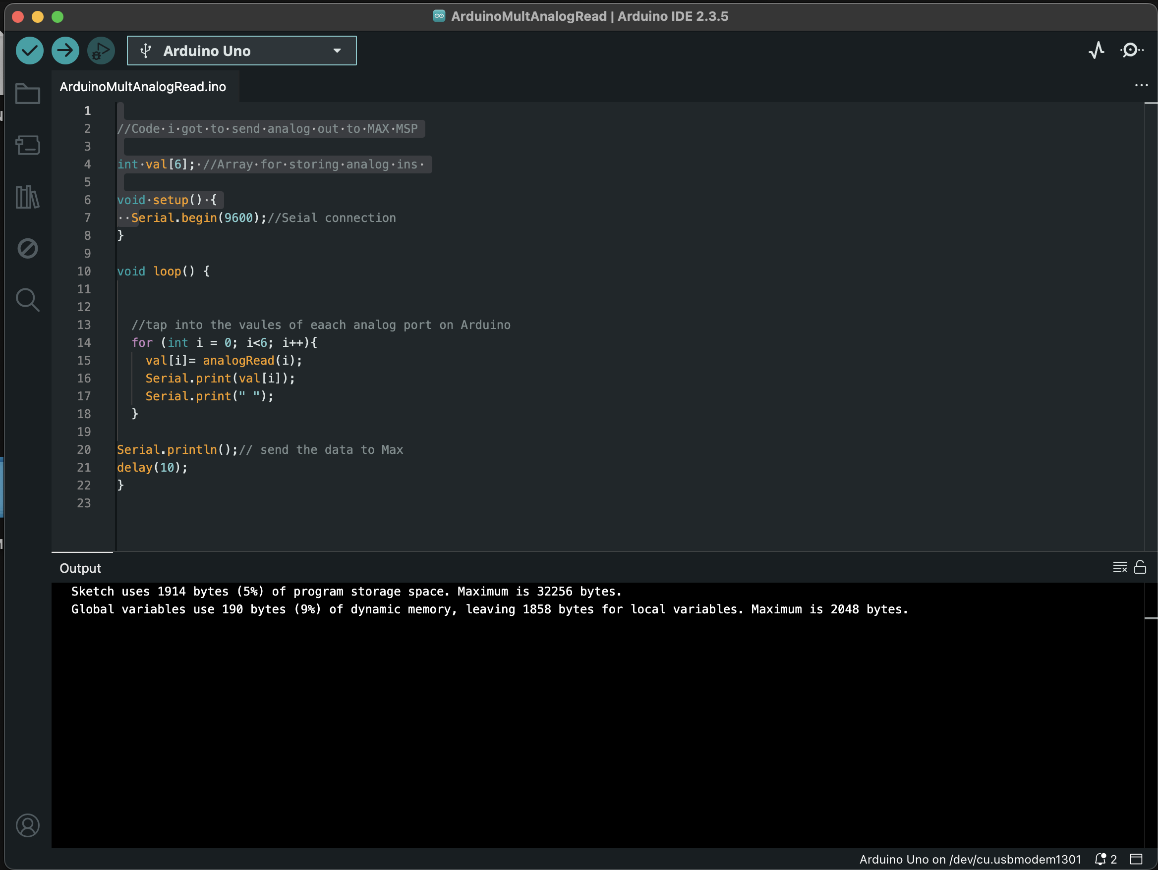
Initally, I wanted to something with potentiometers as they reminded me very much of the knobs we see on MIDI keyboards. I decided to use Max MSP, a digital music coding inteface to see what I could do with analog outputs coming from my two potentiometers. I had two projects.
The first one was using analog outputs from 0 to 1023 to modulate the pitch of a synthesizer. To do this, I mapped the values 0 to 1023 to output as the frequency of a combined sine and saw wave. The result was that the pitch of the wave could be changed by the first potentiometer. Next, the second potentiometer was mapped to volume that way I could control the volume of my synth. Lastly, I used the button as an octave changer. I programmed it so that holding the button down multiplied my frequency of the wave by 2, turning it up an octave.
The other creation was a DJ mixer. I programmed the first capcitor’s output to 1. map to the volume of the first piece of music you inserted, 2. inverse itself and map that to the volume of the second piece of music. This creater a simple fader I could swtich between the two tracks. The second potentiometer remained a volume control. The button allowed you to start/stop both tracks at once so you could play them in sync, and crossfade between them.
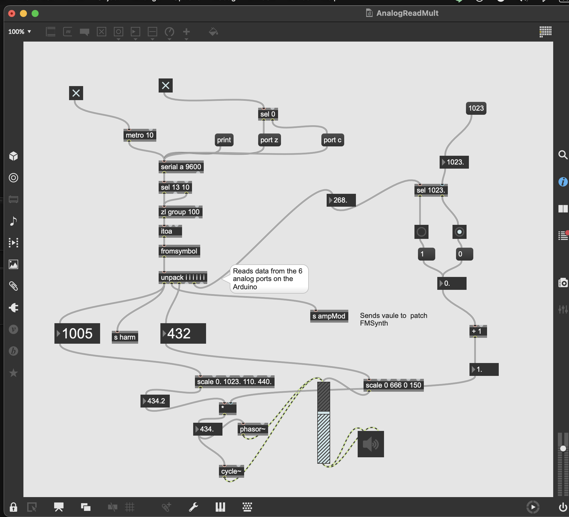

One of the issues that came up was the connections breaking. Sometimes I would not notice and the potentiometer would just stop working. To work around this, I made sure everything was on the table, and none of the wires were in tension. Another issue was that I ony had one 5V power supply. While I could link up both potentiometers in parallel, I found this made the analog outputs shaky. To fix this I actually instead connect one of the two potentiometers to the 1.5V power, then changed to scaling of inputs from 0 to 1023 to 0 to 666, allowing for the same range of volume control.
In the future I could defnitely add more knobs to modulate more aspects of my sound. And as for the DJ mixer, because we do no precieve sound linearly, when the crossfader was between the two songs, the msuic became way too quiet, a non-linear form of mapping for volume could probably fix this. Another thing to improve is to defnitely create some sort of housing, permanently connecting the electornics to create a box-like apparatus as a DJ crossfader.
Week 10 Reading
The part of this article that stuck out to me the most was when the word “tool” was defined. I had never thought of a tool as something that was supposed to amplify human capabiity, yet when he explained his reasoning, using the example with the hammer, it all clicked for me. This meant that when he then goes on to explain the lack to tactile richness in modern day tools as a problem, it makes far more sense for me to see it as a problem.
He then points out that touchscreens should be only a transitionary technology. This really points out the possibilities that I have nver considered due to our complacency in screen usage. I think that being able to control something with our fingers, by dragging something along on a touchscreen is inherently somewhat unnnatrual in terms of what the human mind and body are used to; it is simply an unnatrual way to manipulate ‘objects.’ Yet I believe that in terms of how far away that takes us from perfect design with tactile responses, I would not overlook the human mind’s capacity to ‘fill in the blanks’ and ascertain all that we need to know from the object on the screen. So I personally do not think it is as much of an issue as the article says.
Week 9 Sensor
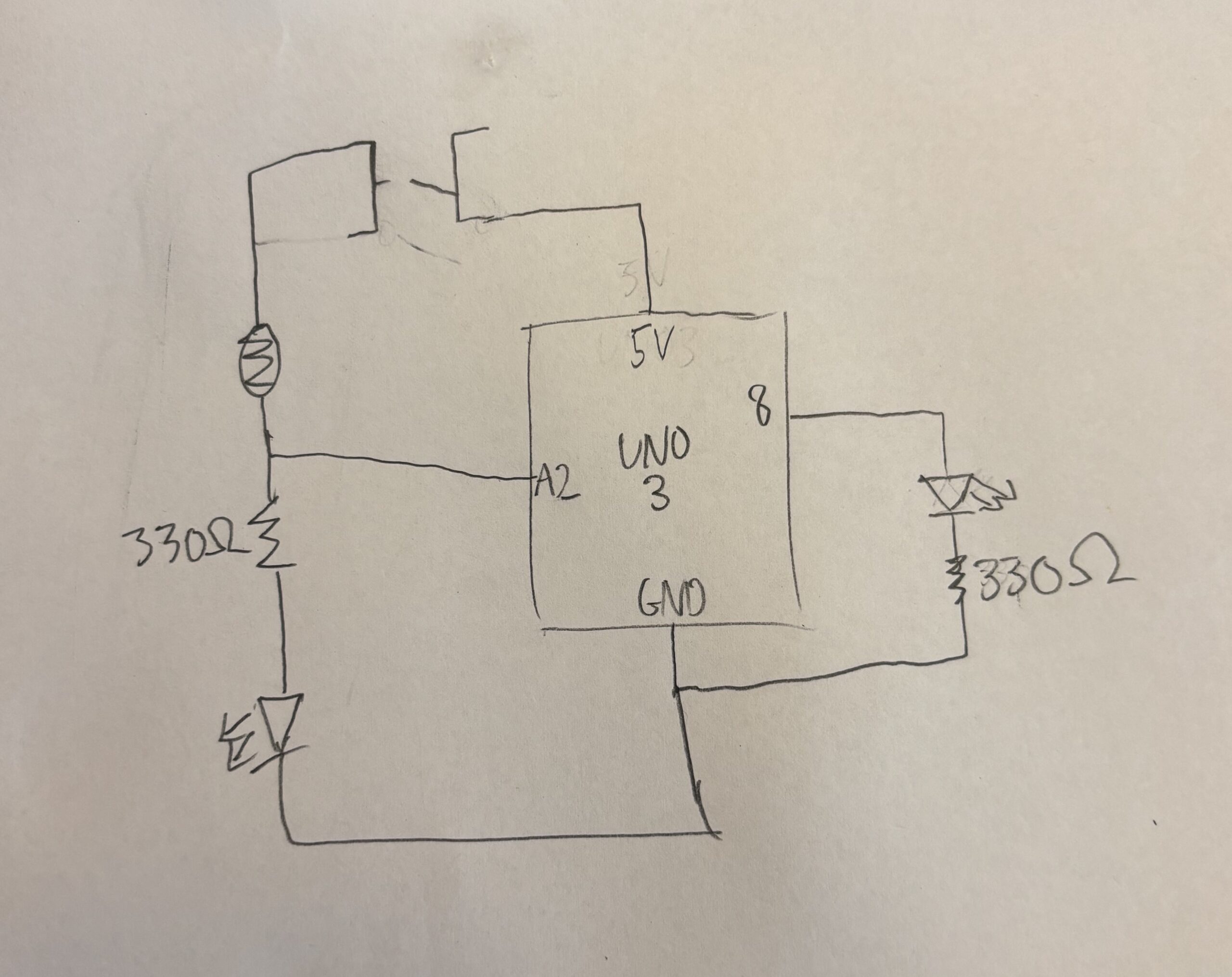
For this project, I decided to use a photoresistor to create a light that detects a light source nearby.
To implement this, I used two circuits; one connected to 5V power supply and another connected to the analog pins, whose power level could be controlled by the analogWrite on IDE. The circuit was not too complicated, connect a manual toggle switch to one side of the circuit, leading into a photoresistor connected to pin A2, leading into the first LED. This would mean the first LED would only light up if the switch was toggled on. This meant that we could see an indicator if the device is working. Next, connected to pin 8 the other LED was connected. This meant that we can control this LED digitally with the arduino. In the circuit, we could use the input we got from A2 to determine if power should be sent to pin 8.

int analogPin = A2;
int lightSensor;
int brightness;
void setup() {
  // put your setup code here, to run once:
pinMode(8, OUTPUT);
pinMode(A2, INPUT);
brightness = 128;

}

void loop() {
  // put your main code here, to run repeatedly:
lightSensor = analogRead(analogPin);
if(lightSensor > 500){
analogWrite(8, 1000);
} else {
analogWrite(8, 0);
}
}
The challenges were that it took a long time to make sure the code and the circuit were both correct. One being correct while the other being wrong would mean the whole thing would not work. Hence, in my making process, I took time testing the two parts individually. Initally there was some confusion on my end pertaining to the difference between analog and digital writing, as using the wrong one meant my LEDs were not lighting up.
This project could definitely be made more complex. I think adding a variety of lights and changing the different thresholds to which each individual LED would light up is a good way to make this project more useful.
Week 9 Reading
One of the most interseting concepts found in “Physical Computing’s Greatest Hits” I found was the tilty tables. While the concept of tilting and how it can alter the objects on a surface is so very intuitive to us, the tilting table adds a degree of complexity compared to something live a wave wall. The tilting allows for another, interesting way for audiences to interact with art in a non-conventional way that is still very rooted in modern day physics.
One of the most out there ideas was also the meditation helpers; devices designed to take away stimulus. This also struck me as very counter-intuitive yet fascinating. Normally, we think about taking away stimulus when it comes to being in a state to meditate, yet this machine attempts to connect the user to the compuation through the interpretation of a series of sensors in a way I think fuses technology and biopsyhcology in a fascinating way.
From the other article, I found the message to be very important and true. Similar to how Norman said doors that need signs are poorly designed, I think an artwork being able to stand alone with less surrounding context is in some shape or form a testament to its thoughtful design. Because the truth is, if one designs their artwork well enough, operation should be intuitive to the user.
The way the article says to indicate what the user should do with the art is so obvious, but when we ourselves are creating art, from an opposing perspective, it is definitely true that these things are just not as obvious as they would if we were not the artist.
Another important note from the article is to listen for feedback. Unlike other mediums, this one is more able to changed over time with feedback. So when for users there is a disconnect in what needs to be done and what they are trying to do, the artist should really take that into account to improve their work.