Final Project-Motion-Activated Mini Garden Visualizer

Project concept

This project was inspired by a real experience on my family’s farm—I saw foxes approaching our chickens at night, and my dad was complaining on how to deal with the situotion it made me think about how to create a simple way to detect movement at a low cost and respond immediately. I wanted something that could work without constant supervision, so I came up with the idea of using an ultrasonic sensor and lights to react when something gets close.

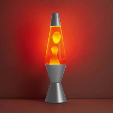
From there, I built a mini garden setup using individual RGB LEDs and connected it to P5.js for visual feedback. I started with a different idea—using sound and an LED strip—but changed direction after facing hardware limitations. and honestly I love how it turned better. That process helped shape the final concept,i also wanted to create something similar to lava lamps that’s why ii ended up doing the visuals in p5.js similar to the blobs in the lava lamps which now works as both an interactive installation and a practical assistive device for animal and crop protection.

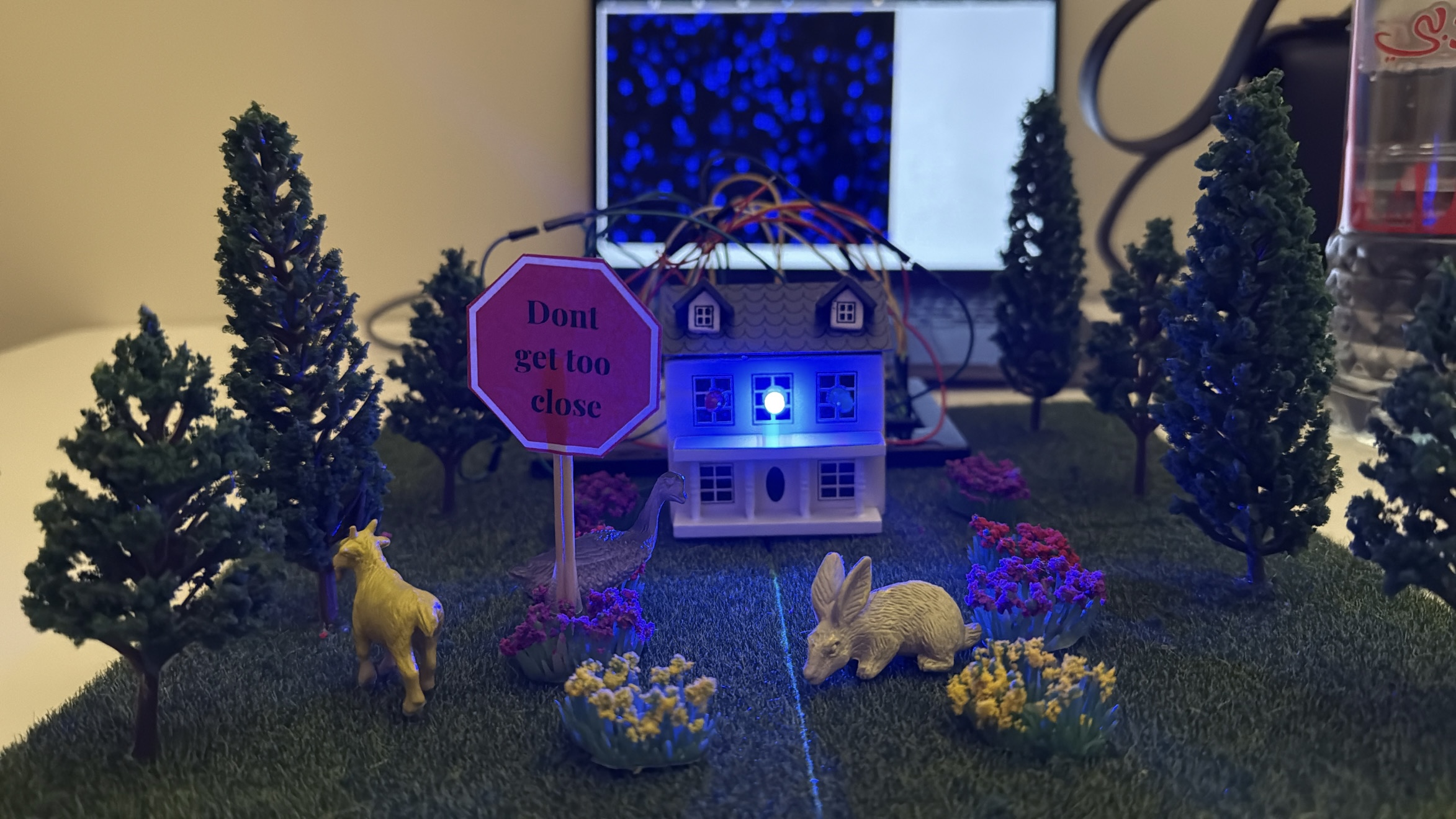
My final project is the Motion-Activated Mini Garden/farm Visualizer, an interactive installation that responds to movement and presence using an ultrasonic sensor. – house and the garden I built . When someone approaches the garden, the LEDs light up based on proximity—closer movement causes brighter, more vibrant lights, while standing farther away results in dimmer, calmer effects.

-blue is for far away

-green in for in the middle

-red is for very close

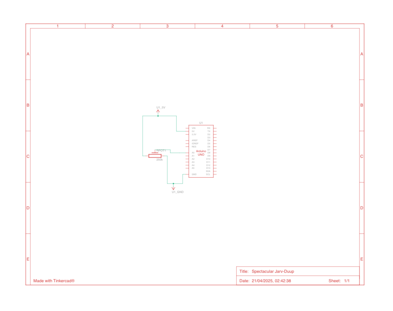
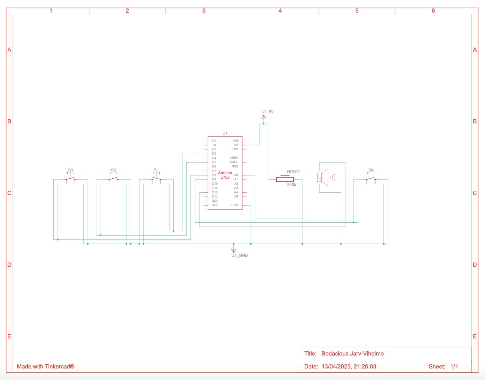
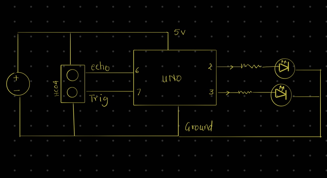
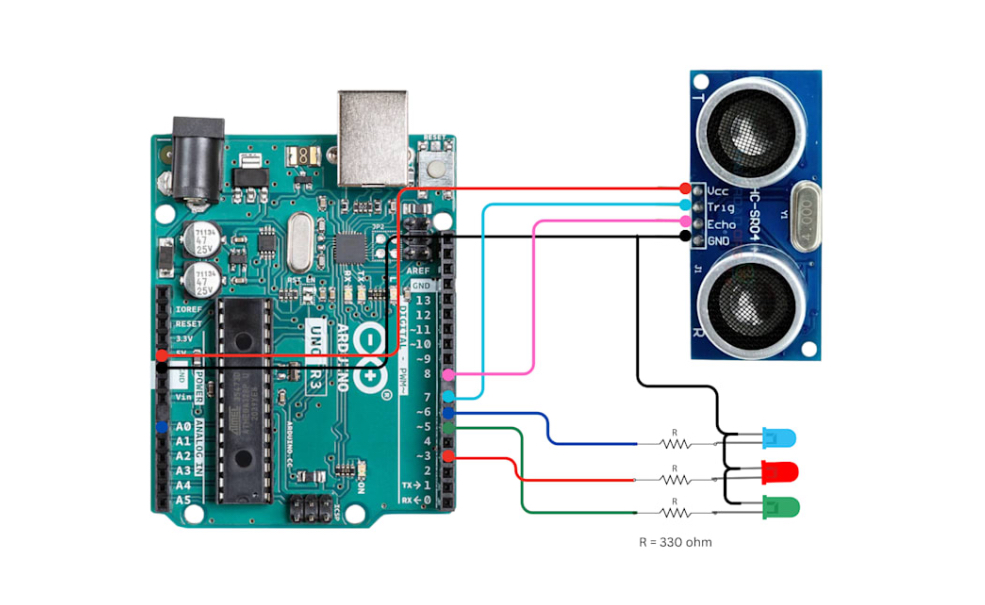
The schematic digram:

Aruidno code:

// HC-SR04 Ultrasonic Sensor Pins
#define TRIG_PIN 7
#define ECHO_PIN 8

// RGB LED Pins
#define RED_LED_PIN 3
#define GREEN_LED_PIN 5
#define BLUE_LED_PIN 6

long duration;
int distance;

void setup() {
  Serial.begin(9600);

  // Sensor Pins
  pinMode(TRIG_PIN, OUTPUT);
  pinMode(ECHO_PIN, INPUT);

  // RGB LED Pins
  pinMode(RED_LED_PIN, OUTPUT);
  pinMode(GREEN_LED_PIN, OUTPUT);
  pinMode(BLUE_LED_PIN, OUTPUT);

  turnOffAll(); // Ensure LEDs are off initially
}

void loop() {
  // Trigger the ultrasonic sensor
  digitalWrite(TRIG_PIN, LOW);
  delayMicroseconds(2);
  digitalWrite(TRIG_PIN, HIGH);
  delayMicroseconds(10);
  digitalWrite(TRIG_PIN, LOW);

  // Read echo and calculate distance (cm)
  duration = pulseIn(ECHO_PIN, HIGH);
  distance = duration * 0.034 / 2;

  // Print distance to serial
  // Serial.print("Distance: ");
  Serial.println(int(distance));
  // Serial.println(" cm");

  // LED logic based on distance
  if (distance < 10) {
    setColor(255, 0, 0);   // Close → Red
  }
  else if (distance >= 10 && distance <= 30) {
    setColor(0, 255, 0);   // Medium → Green
  }
  else {
    setColor(0, 0, 255);   // Far → Blue
  }
  delay(100);
}

// Control RGB LEDs using digital logic
void setColor(uint8_t r, uint8_t g, uint8_t b) {
  digitalWrite(RED_LED_PIN, r > 0 ? HIGH : LOW);
  digitalWrite(GREEN_LED_PIN, g > 0 ? HIGH : LOW);
  digitalWrite(BLUE_LED_PIN, b > 0 ? HIGH : LOW);
}

void turnOffAll() {
  digitalWrite(RED_LED_PIN, LOW);
  digitalWrite(GREEN_LED_PIN, LOW);
  digitalWrite(BLUE_LED_PIN, LOW);
}

p5.js code:

let serial;
let distance = 0;

function setup() {
  createCanvas(windowWidth, windowHeight);
  background(0);

  serial = new p5.SerialPort();
  serial.on('connected', () => console.log("Connected to Serial!"));
  serial.on('data', serialEvent);
  serial.open("/dev/tty.usbmodem101"); // Change to your actual COM port
  console.log();
}

function draw() {
  background(0, 30);

  // let size = map(distance, 0, 1023, 10, 100); // Adjust if your micValue goes up to 1023
  let size = 30;
  let col;
  if (distance < 10) {
    col = color(255, 0, 0); // Low
  } else if (distance < 30) {
    col = color(0, 255, 0); // Medium
  } else {
    col = color(0, 0, 255); // High
  }

  fill(col);
  noStroke();

  for (let i = 0; i < 20; i++) {
    ellipse(random(width), random(height), size);
  }
}


function serialEvent() {
  let data = serial.readLine().trim();
  if (data.length > 0) {
    distance = int(data);
    console.log("mic:", distance);
  }
}

A short clip showing someone approaching the mini garden. As they move closer, the LED lights respond by changing color, and the screen displays animated, color-shifting blobs in sync with the movement:

https://drive.google.com/drive/u/0/folders/1Kk2lkQgoAyybXSYWVmY2Dog9uQVX_DMq

The process:

How does the Implementation work

An ultrasonic sensor detects how close a person or object is to the garden. This distance value is read by the Arduino and mapped to RGB LED colors. The same data is also sent over serial communication to P5.js, which animates abstract blobs on the screen. These blobs shift in speed, size, and color based on how close the user is, creating a consistent and engaging visual language that mirrors the physical lighting

interaction design :

The design of the project relies on intuitive interaction. Users are not given instructions—they are simply invited to explore. As they move closer to the garden, the changes in light and digital visuals guide them to understand the system’s behavior. This makes the experience playful and discoverable.

Distance from Sensor LED Color P5.js Visual Response
Less than 10 cm Red Fast motion, bright red blobs
10–30 cm Green Medium speed, green blobs
More than 30 cm Blue Slow, soft blue motion

A clear explanation focusing  on how the device assists with animal and crop protection,

Assistive Use Cases: Protecting Animals and Crops:

This motion-activated system has strong potential as an assistive device in agricultural and animal care settings, where clear and reliable response is essential.

For Animals (Livestock Protection):

The system can be used to monitor the area around livestock enclosures such as sheep pens, chicken coops, or goat fields. When a predator like a fox, stray dog, or wild animal approaches, the ultrasonic sensor detects motion, triggering an immediate response—such as flashing lights, alarms, or future-connected alerts. This helps deter predators non-invasively and gives farmers real-time awareness of threats without being physically present.

For Crops (Field and Garden Monitoring):
In gardens, greenhouses, or open crop fields, this system can be used to detect intruders, trespassers, or large animals that may damage crops. The lights act as a deterrent, and with future improvements (like wireless communication), it could alert the farmer via phone or connected system. This is especially helpful at night or in remote locations, allowing for continuous, low-maintenance monitoring.

Assistive Use Case: Law Enforcement and Security

This motion-activated system can be effectively adapted for law enforcement and security by serving as a low-cost, responsive perimeter monitoring tool. Installed at property lines, remote checkpoints, or restricted access areas, the device detects unauthorized movement and can trigger lights, sirens, or silent alerts depending on the situation. With future enhancements, it could be linked to mobile devices or integrated with camera systems for real-time surveillance. Its compact, portable design makes it suitable for temporary deployments during investigations, search operations, or event monitoring, offering a clear and reliable response without requiring continuous human oversight.

what im proud of :

  • Creating a synchronized experience between physical light and digital visuals

  • Making the interaction intuitive and inviting, even without instructions

  • Learning how to connect Arduino to P5.js and achieve stable real-time communication

  • Areas of improvement
    • Add wireless communication (e.g., Bluetooth or Wi-Fi) to trigger mobile alerts

    • Improve the physical build by embedding LEDs into real plants or creating a more polished enclosure

    • Include a reset or mode switch to allow the user to cycle through different animation types

  • The final outcome:
  • Last video:
  • https://drive.google.com/drive/u/0/folders/1Kk2lkQgoAyybXSYWVmY2Dog9uQVX_DMq

User Testing-Week 13

Final Concept: Motion-Activated Mini Garden Visualizer

My final project is the Motion-Activated Mini Garden Visualizer—an interactive installation that uses an ultrasonic sensor and individualLEDs embedded in miniature garden that I built. The project simulates how a garden might come to life in response to presence and movement. Instead of using a microphone to detect sound, the system now detects distance and motion. As a person approaches, LEDs light up in various colors, mimicking the way plants might react to human presence.

This visual experience is enhanced by a P5.js sketch that features lava lamp-inspired blobs. These blobs move and shift color based on proximity—creating a unified physical-digital display that changes in mood depending on how close someone is to the garden.

Why These Changes Were Made

Originally, the project was a mood tree visualize using an LED strip and microphone sensor. However, due to hardware limitations (the Arduino could only power 5 LEDs reliably), I shifted to using individual LED lights. At the same time, I replaced the microphone sensor with an ultrasonic sensor to create a more responsive and stable interaction system. These changes also allowed me to design a mini garden setup that feels more visually integrated and conceptually clear.

Real-World Relevance & Future Use Cases

This concept has real potential for garden and farm environments:

In gardens it could act as a calming, responsive lighting system.
On farms, the same setup could help detect animals like foxes approaching livestock (e.g., sheep). In the future, it could be upgraded with:

Sirens or alerts- when something comes too close.
Automatic light deterrents- to scare animals away.
Wireless notifications- to a user’s phone.

User Testing Reflection

I conducted user testing without providing any instructions, observing how people interacted with the installation:

What worked well:
Users naturally moved closer to the garden and quickly noticed that proximity activated the lights**. The more they explored, the more they connected movement with the garden’s glowing response.

What caused confusion:
each lights colour meant what- where was the sensor exactly

What I had to explain:
I explained the system was using

motion sensing was a bit confusing , and once clarified, users became more engaged.

How I’ll improve the experience:
To make it clearer, I plan to place a small instruction that says:
“Walk closer to bring the garden to life.”
This subtle cue will help guide new users and enhance intuitive interaction.

Final Thoughts

Changing from sound-based input to motion-based sensing not only solved technical challenges, but also made the experience smoother and more immersive. The use of single LEDs in a mini garden created a more grounded and intimate installation. These changes—while unplanned—ultimately led to a more thoughtful, future-facing project that bridges creative expression with real-world functionality.

The video:

https://drive.google.com/drive/u/0/folders/1Kk2lkQgoAyybXSYWVmY2Dog9uQVX_DMq


Finalized Concept-week12

For my final project, I’m creating an interactive Mood Tree Visualizer—a small Christmas tree decorated with RGB LEDs that change colors based on sound  input. The physical tree will be paired with lava lamp-inspired digital visuals in P5.js, creating a cohesive, immersive experience that blends the physical with the virtual. The LEDs on the tree and the blobs on the screen will respond dynamically to sound levels (like clapping, talking, or music) and mood selections .

This playful project is about visualizing emotions in a cozy, festive, and engaging way, letting users express energy levels through both the physical glow of the tree and the flowing digital visuals.

inspiration:

Arduino : Inputs & Outputs:

sound sensor:Captures ambient sound intensity. Louder sounds trigger more active LED patterns and more dynamic P5.js animations.

  • Calm: Blues/Purples

  • Medium: Greens

  • Excited: Reds/Orange

    P5.js Program Design: Inputs & Outputs

    • Inputs from Arduino:

      • Sound Levels:
        Modulate the size, speed, and behavior of the lava blobs.

      • Mood Selection:
        Switch between color palettes and animation styles that match the LED colors.

or instead I will create My final project is a Mood House Visualizer a small interactive installation where a miniature house lights up in response to sound. Using an Arduino with a microphone sensor, I will control five RGB LEDs embedded because Arduino doesn’t have enough current for more than 5 led lights or I might just add the led lights for each colors and I will make a mini garden it will act the same way the tree should act the difference is going to be in the appearance of the project

week 11-Serial Communication

For this project, I created an interactive system that integrates Arduino with p5.js, using Node.js for serial communication, allowing seamless interaction between the hardware (Arduino) and software (p5.js sketch).

The project consists of three tasks, each demonstrating different ways Arduino sensors and outputs can interact with visual and digital elements in p5.js. Below is a detailed description of each task, including the setup, code, and outcomes.

Task 1: Control Ellipse Horizontal Position with Arduino Sensor

Goal: Use a potentiometer connected to Arduino to control the horizontal position of an ellipse in p5.js.

Task 2: Control LED Brightness from p5.js Mouse Position

Goal: Use the mouse cursor in p5.js to control the brightness of an LED connected to Arduino.

Task 3: Gravity-Wind Sketch with LED Bounce Feedback

Goal: Modify the gravity-wind sketch (from Aaron Sherwood’s example) so that:

-A potentiometer controls the wind force.

-Each time the ball bounces, an LED lights up briefly.

systemic diagram:

Conclusion:

This project showcased the flexibility of combining Arduino and p5.js via Node.js, enabling rich interaction between hardware and software. The local setup allowed full control over serial communication, overcoming the browser-based limitations.

Future Improvements:

  • Add sound effects when the ball bounces.

  • Use multiple sensors to control more aspects of the sketch.

  • Expand interaction with other hardware components (motors, buzzers).

p5.js

The codes:

let serial;
let sensorValue = 0;

function setup() {
createCanvas(400, 400);
serial = new p5.SerialPort();

serial.on('list', printList);
serial.on('connected', serverConnected);
serial.on('open', portOpen);
serial.on('data', gotData);
serial.on('error', serialError);
serial.on('close', portClose);

serial.list(); // get list of serial ports
serial.openPort('COM3'); // replace with your actual port
}

function gotData() {
let val = serial.readLine().trim();
if (val !== "") {
sensorValue = int(val);
print(sensorValue);
}
}

function draw() {
background(220);
ellipse(map(sensorValue, 0, 1023, 0, width), height / 2, 50, 50);
}

// Optional helper functions
function printList(portList) {
console.log("List of Serial Ports:");
for (let i = 0; i < portList.length; i++) {
console.log(i + ": " + portList[i]);
}
}

function serverConnected() {
console.log('Connected to server.');
}

function portOpen() {
console.log('Serial port opened.');
}

function serialError(err) {
console.log('Serial port error: ' + err);
}

function portClose() {
console.log('Serial port closed.');
let serial;

function setup() {
createCanvas(400, 400);
serial = new p5.SerialPort();

serial.on('open', () => console.log("Serial port opened"));
serial.openPort('COM3'); // change this if needed
}

function draw() {
background(220);

let brightness = int(map(mouseX, 0, width, 0, 255));
fill(brightness);
ellipse(width / 2, height / 2, 100, 100);

serial.write(brightness + "\n"); // send brightness to Arduino
void setup() {
Serial.begin(9600);
pinMode(9, OUTPUT); // LED on pin 9
}

void loop() {
int sensor = analogRead(A0);
Serial.println(sensor);
delay(10); // short delay

if (Serial.available()) {
char c = Serial.read();
if (c == 'B') {
digitalWrite(9, HIGH);
delay(100);
digitalWrite(9, LOW);
}
}
}
void setup() {
Serial.begin(9600);
pinMode(9, OUTPUT); // LED on pin 9
}

void loop() {
int sensor = analogRead(A0);
Serial.println(sensor);
delay(10); // short delay

if (Serial.available()) {
char c = Serial.read();
if (c == 'B') {
digitalWrite(9, HIGH);
delay(100);
digitalWrite(9, LOW);
}
}
}


let serial;
let sensorValue = 0;
let windForce = 0;
let ball;
let gravity;

function setup() {
createCanvas(400, 400);
serial = new p5.SerialPort();

// Open the correct serial port
serial.openPort('COM3'); // ← Change to your actual Arduino COM port!

// When data comes in from Arduino
serial.on('data', gotData);

gravity = createVector(0, 0.2);
ball = new Ball();
}

function gotData() {
let val = serial.readLine().trim();
if (val !== "") {
sensorValue = int(val);
windForce = map(sensorValue, 0, 1023, -0.2, 0.2);
print("Sensor:", sensorValue, "→ Wind:", windForce);
}
}

function draw() {
background(240);

// Apply wind from sensor and gravity
ball.applyForce(createVector(windForce, 0));
ball.applyForce(gravity);

// Update + show ball
ball.update();
ball.display();

// If ball bounced, tell Arduino to blink LED
if (ball.isBouncing()) {
serial.write('B\n');
}
}

class Ball {
constructor() {
this.position = createVector(width / 2, 0);
this.velocity = createVector();
this.acceleration = createVector();
this.radius = 24;
this.bounced = false;
}

applyForce(force) {
this.acceleration.add(force);
}

update() {
this.velocity.add(this.acceleration);
this.position.add(this.velocity);
this.acceleration.mult(0);

// Bounce off bottom
if (this.position.y >= height - this.radius) {
this.position.y = height - this.radius;
this.velocity.y *= -0.9;
this.bounced = true;
} else {
this.bounced = false;
}
}

isBouncing() {
return this.bounced;
}

display() {
fill(50, 100, 200);
noStroke();
ellipse(this.position.x, this.position.y, this.radius * 2);
}
}

Arduino code:

int sensorPin = A0; // Potentiometer connected to analog pin A0
int sensorValue = 0; // Variable to store the potentiometer value

void setup() {
Serial.begin(9600); // Start serial communication at 9600 baud rate
}

void loop() {
sensorValue = analogRead(sensorPin); // Read the potentiometer value (0-1023)
Serial.println(sensorValue); // Send the value to the computer
delay(10); // Short delay to prevent overloading serial data
}
void setup() {
Serial.begin(9600);
pinMode(9, OUTPUT); // LED connected to pin 9 (PWM)
}

void loop() {
if (Serial.available()) {
int brightness = Serial.parseInt();
brightness = constrain(brightness, 0, 255); // safety check
analogWrite(9, brightness);
}
}
void setup() {
Serial.begin(9600);
pinMode(9, OUTPUT); // LED on pin 9
}

void loop() {
int sensor = analogRead(A0);
Serial.println(sensor);
delay(10); // short delay

if (Serial.available()) {
char c = Serial.read();
if (c == 'B') {
digitalWrite(9, HIGH);
delay(100);
digitalWrite(9, LOW);
}
}
}

The videos:

https://drive.google.com/drive/u/0/folders/1Kk2lkQgoAyybXSYWVmY2Dog9uQVX_DMq


Final project-Mood Light Visualizer-week 11

I will create an interactive mood light visualizer that responds to both sound and touch. I’ll use an Arduino with a microphone sensor to detect sound levels like claps or voice, and a touch sensor or button to switch between different mood settings. The sound data will be sent from Arduino to P5.js, where I’ll visualize it with animated shapes and changing colors on the screen.

The visuals in P5 will shift depending on how loud the sound is, creating a more active or calm display. For example, soft sounds might create slow-moving blue waves, while loud sounds can trigger bright, fast animations. With the touch sensor, users can choose between different color moods like calm (blues), excited (reds), or dreamy (purples). I’ll also add LED lights to the Arduino that change color to match the selected mood.

This system will allow people to express their emotions or interact through sound and touch in a playful, visual way. It’s a simple setup, but it creates an engaging experience by combining physical input with real-time digital response.

Reading reflection- week 11

Reading Design Meets Disability really changed the way I think about design. Before this, I used to see design as something focused on looks or style, not really about who it’s for. But this reading made me realize that design is also about who gets included or left out. I liked the part where it said that designing for disability actually helps everyone. It reminded me of curb cuts on sidewalks. They were made for wheelchair users but also help people with strollers or suitcases. It made me think that maybe good design should always start with accessibility, not add it later.

Another thing that stood out to me was how design shows what we think is “normal.” I never thought about how something like a prosthetic leg can carry stigma, while glasses don’t, even though both are assistive. The difference is that glasses have been accepted and even turned into fashion, while prosthetics haven’t been treated the same way. It made me wonder if more expressive or creative prosthetic designs would change how people see them. This reading made me realize that design isn’t just about making things work,it can also change how we feel about our bodies and each other.

Week 10-Sound, Servo motor, Mapping

For our group assignment, we built a simple digital musical instrument using an Arduino board. Our project was inspired by the children’s song Mary Had a Little Lamb, and we recreated the melody using four push buttons for four of the notes, C, D, E and G respectively. Each button acts as a digital sensor, triggering specific musical notes when pressed. The tones are played through a mini speaker connected to the Arduino, allowing the tune to be heard clearly. This created a very basic piano-style interface, with each button mapped to one of the notes in the song.

In addition to the buttons, we used a potentiometer as our analog sensor. This allowed us to control the frequency of the sound in real time. As the knob is turned, the pitch of the notes changes slightly, giving the player the ability to customize how the melody sounds. We mapped the frequency from 500-1000 Hz for this. It made the experience more interactive and demonstrated how analog inputs can add expressive control to digital systems. We also added some labels to the buttons so that it would be easier to play the music.

As for problems or challenges, we didnt really have any specific problems with the circuit other than loose wires or something which was fixed after debugging and checking again. Something we understood from working together is that having two different perspectives helps a lot in solving problems and finding ideas.

We see a lot of potential for expanding this project in the future. One idea is to add a distance sensor to control volume based on hand proximity, making it even more dynamic. Another would be adding LEDs that light up with each button press to provide a visual cue for the notes being played. We’re also considering increasing the number of buttons to allow more complex songs, and possibly adding a recording function so users can capture and replay their melodies.

It was a fun and educational project that helped us better understand the relationship between hardware inputs and interactive sound output. It was exciting to bring a classic tune to life through code, sensors, and a mini speaker!

The code:

const int buttonPins[4] = {3, 5, 8, 9}; // buttons

//frequency for each button
int frequencies[4] = {262, 293, 330, 392}; //C, D , E , G notes
int potValue = 0; //to store potentiometer value

void setup() {
//initialising buttons pins
for (int i = 0; i < 4; i++) {
pinMode(buttonPins[i], INPUT_PULLUP);
}

//for debugging
Serial.begin(9600);

//speaker pin for output
pinMode(12, OUTPUT);
}

void loop() {
//read the potentiometer value
potValue = analogRead(A0);

//map the potentiometer value to a frequency range 500-1000
int adjustedFrequency = map(potValue, 0, 1023, 500, 1000);

//for button and the corresponding note
for (int i = 0; i < 4; i++) {
if (digitalRead(buttonPins[i]) == LOW) { // Button is pressed (LOW because of INPUT_PULLUP)
tone(12, frequencies[i] + adjustedFrequency);
Serial.print("Button ");
Serial.print(i+1);
Serial.print(" pressed. Frequency: ");
Serial.println(frequencies[i] + adjustedFrequency); //serial monitor
delay(200);
}
}

//to stop the tone when buttons arent being pressed
if (digitalRead(buttonPins[0]) == HIGH && digitalRead(buttonPins[1]) == HIGH &&
digitalRead(buttonPins[2]) == HIGH && digitalRead(buttonPins[3]) == HIGH) {
noTone(12);
}
}

systematic diagram:

the video:

https://drive.google.com/drive/u/0/folders/1Kk2lkQgoAyybXSYWVmY2Dog9uQVX_DMq


the video of the potentiometer usage:

https://drive.google.com/drive/u/0/folders/1Kk2lkQgoAyybXSYWVmY2Dog9uQVX_DMq


Reading reflection-week 10

Reading A Brief Rant on the Future of Interaction Design honestly made me pause and look around at all the tech I use every day. The author’s frustration really hit home, especially the part about how everything has become a flat screen with no real feedback. It reminded me of how awkward it feels to use a touchscreen on a stove or in a car just to do something simple, like turn down the heat or change the music. Those actions used to be so quick and intuitive. I think the author has a point—we’ve lost touch with how things feel. It’s like we’re designing for appearances now, not for actual human comfort. I didn’t feel like he was biased in a bad way he just seemed passionate, like someone who really cares about how design affects everyday life.

What stuck with me most was how much we’ve adapted to poor interaction design without even noticing. I catch myself getting used to frustrating interfaces all the time, and this reading made me realize we shouldn’t have to settle for that. It made me wonder: what would technology look like if we designed it based on how our bodies naturally move and react? That question stayed with me after I finished reading. It also raised another thought—how do we balance innovation with simplicity? Just because something’s high-tech doesn’t mean it’s better. I think future designers, myself included, need to remember that. This reading didn’t completely change my beliefs, but it definitely sharpened them.

Arduino: analog input & output

This week I used both an analog and a digital sensor to control two LEDs in different ways. I used the ultrasonic distance sensor to measure distance. For the digital sensor. My setup controls two LEDs: one blinks and the other changes brightness using PWM.

Here’s how it works:
LED1, connected to a regular digital pin, blinks faster when an object is closer and slower when it’s farther away. The delay between blinks is based on the distance in centimeters. So the closer the object, the faster the LED blinks. If the object is far, the LED blinks slowly.

LED2, connected to a PWM pin, changes brightness based on the same distance. But instead of getting dimmer when the object is far (which is more common), I made it do the opposite—it’s dim when the object is close and bright when it’s far away. I know it’s the reverse of what people usually do, but I wanted to try something different and see how it looked in action.

the code :

// Pin definitions
const int trigPin = 7;     // HC-SR04 trigger pin
const int echoPin = 6;     // HC-SR04 echo pin
const int led1Pin = 2;     // LED1 pin (digital)
const int led2Pin = 3;     // LED2 pin (PWM)

// Variables
const int maxDistance = 255;  // Maximum meaningful distance (cm)
int distance = 0;             // Measured distance in centimeters
int brightness = 0;           // Variable for brightness

void setup() {
  Serial.begin(9600);
  pinMode(led1Pin, OUTPUT);
  pinMode(led2Pin, OUTPUT);
  pinMode(trigPin, OUTPUT);
  pinMode(echoPin, INPUT);
}

long getUltrasonicDistance() {
  digitalWrite(trigPin, LOW);
  delayMicroseconds(2);
  digitalWrite(trigPin, HIGH);
  delayMicroseconds(10);
  digitalWrite(trigPin, LOW);
  return pulseIn(echoPin, HIGH);
}

void loop() {
  // Measure distance
  distance = 0.01723 * getUltrasonicDistance();
  
  // Cap the distance reading
  if(distance > maxDistance) distance = maxDistance;
  if(distance < 2) distance = 2;  // HC-SR04 minimum range
  
  // Serial output
  Serial.print(distance);
  Serial.println(" cm");
  
  // LED1: Blink with distance-dependent delay (capped)
  digitalWrite(led1Pin, HIGH);
  delay(distance);
  digitalWrite(led1Pin, LOW);
  delay(distance);
  
  // LED2: Brighter when closer, dimmer when farther
  //brightness = map(distance, 2, maxDistance, 255, 0); // Inverted mapping
  //brightness = constrain(brightness, 0, 255); // Ensure valid PWM
  //Serial.println(brightness);
  brightness = distance;
  analogWrite(led2Pin, brightness);

video:

https://drive.google.com/drive/u/0/folders/1Kk2lkQgoAyybXSYWVmY2Dog9uQVX_DMq

future improvement:

In the future, I’d like to add sound that reacts to distance, like pitch changes as you move closer or farther. I also want to make the project more interactive overall—maybe by adding more sensors or letting users trigger different responses through movement or touch. This would make the experience feel more playful and alive.

schematic:

Week- 9 reading

This week’s readings made me think about how important it is to be okay with things not always working out. In Physical Computing’s Greatest Hits and Misses, I liked how it showed both the successful projects and the ones that didn’t go as planned. That felt real. I often feel like everything I make has to be perfect, but this reminded me that trying new things and failing is part of the process. It also made me wonder—what really makes something a “failure”? If people still interact with it or feel something from it, maybe it still has value. I want to be more open to things going wrong, because those moments can lead to better ideas.

The second reading, Making Interactive Art: Set the Stage, Then Shut Up and Listen, really stayed with me. I’m used to explaining my work a lot or trying to get people to understand exactly what I meant. But this reading made me realize that sometimes the best thing I can do is let go and let the audience explore for themselves. I don’t fully agree with the idea that artists should just “shut up,” because I think some guidance can help people connect. Still, I like the idea of trusting people more. It made me think about how I can make work that gives people space to feel, move, and react in their own way, without me controlling every part of the experience.