Week 14 – Final Project Show Case:

Video:

Fixes made:

The p5 program had issues with counting the score and incrementing it. Turns out, there was a Upper case – lower case difference between the Serial.print by arduino and what was being expected by the P5 program. This in return rendered no score on the P5 canvas. This was identified and fixed before the showcase.

The P5 canvas also had text mis-alignment, which was worked towards as well.

In addition to it, the bearing  kept on falling off, this was then fixed by sharpening the wooden stick using a giant sharpner Mr Dustin got me. Using it, the diameter was reduced enough to fit into the hole inside the bearing!

Drilling a pilot hole to put a M3 screen through was hard, hence didn’t take the risk, but implementation of that surely would have made sure it never came off.

Feedback from the audience:

The audience loved the action packed mechanical project. The best part was the frustration and the eagerness to compete. The concept of timer garnered total attention, and moving mechanism alongside trajectory of markers and tape made it unique in its on way. Some people did suggest going for more easier level, which was taken into consideration.

The open-rounded lid as stationary holder was used. Maybe in the future, one with bigger diameter can be used to facilitate the user in their gameplay.

So far, what stood out for me as complement, was the genuineness  the project had in terms of how it was built and was structured. I take pride in getting my hands dirty and full of splinters and hot glue, and hence, I found it to be an overall success.

Of course the release mechanism would have taken to it to next level, and that is something I will be working towards over the Summers!


Week 13 – User Testing and Interaction

Video Demo:

note- instructions were provided in this video, after the user was unable to lock the target. In all fairness, such intricacy was bounded to game rules and hence was required to be briefed so that he can continue operating it.

Initial Impression:

The initial Impression of the project was awe-inspiring for most of the audience, especially for the male audience. One can sense the ‘awesomeness’ – quoting my friend by merely looking at the rough-tough built of the design. For the female audience, the lack of color-scheming made it less appealing. This was concluded after asking 8 of my classmates to test out my project.

Haris for instance was thrilled to see the project and idea come to life! The very idea of gamifying putting things back into their place with scoring mechanism was a huge plus point according to him. Overall, the functional and responsive piece of wood, cardboard, and PVC pipe did pique their curiosity. Unlike conventional design mechanism, this was something different. I am grateful to professor for approving and allowing this project. A mix of Cornhole game and concept of  re-racking of equipment after its use. To make it appropriate for the settings, the launcher launches out markers and scotch tape into the pencil holder – with a button attached to the bottom.

Areas with successful interaction:

The major area of success was the button movement and LED correspondence to the game state. The game when in MENU state, turns on the red LED. When start button pressed, it triggers the game to start both in P5.js and inside Arduino program. This turns on the blue LED. This is when the user can control the movement of the canon. The button placement reflects the direction of movement, thus users had no problem interacting with the system.

Confusion and explanation needed:

However, the confusion arose when they were unable to lock and shoot. Provided that instructions were not given regarding game rule, they continued to either move the launcher back and forth, or tried fiddling around with the inner barrel.

Conclusion:

Label the buttons and LED to allow for smoother user interface!

Week 13 – Project Concept & Work in Progress

Project Concept & Work in Progress

Introduction:

The final project is turning out to be great! A concept that combines Cornhole game, as mentioned earlier, and a gamified  message of putting your stuff back in their place. Seeing IM lab assistants go around, cleaning up after the students made me wonder what can get the message across while making it bother interactive and interesting. Something that makes people keep coming back to your project.

Project Development:

The first take was the hardware. The idea is to incorporate a release mechanism alongside a barrel. To construct a barrel, an idle sturdy cardboard was salvaged from the IM lab. It was cut down into two with a saw. Each being 44 cm in length and 50 mm in diameter approximately.

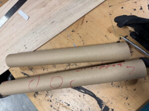
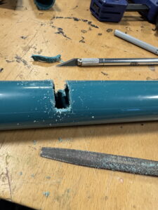
Then, a broken PVC pipe, which was originally part of a discard vacuum cleaner was used. This was done to recycle discarded item. It was clamped and then cut to fit the size of the barrel.

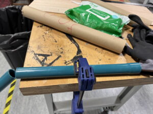
Slit/ cavity was then made into the pipe like structure for the release mechanism to latch into.

The original idea was to shoot pingpong balls. Since the pipe was hollow, it was filled with some plastic trash, and broken items to give it mass. The basic principles of conservation of momentum were to be applied.

M1V1 = M2V2 with 1 indicating the pipe , and 2 indicating the pingpong ball. Hence the ball will have greater speed to make up for the lesser mass.

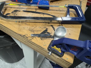
Next, the discarded utensils like spoon was used. Clamped into place, I used saw to cut it in half. The other half was to be used as the release/lock mechanism for the launcher.

Next, for the tension, instead of just few handful rubber bands, in the spirit of reuse and recycle, I extracted the elastic from the masks.

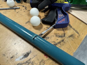
Next, pilot holes were drilled using a drill machine with larger drill bit. M4 screws with washers and nuts were added to hold the rubber bands in place. A bit distance was kept between the washer and nut to hook the elastic inside them, and also to avoid the tail end obstruction with the PVC.

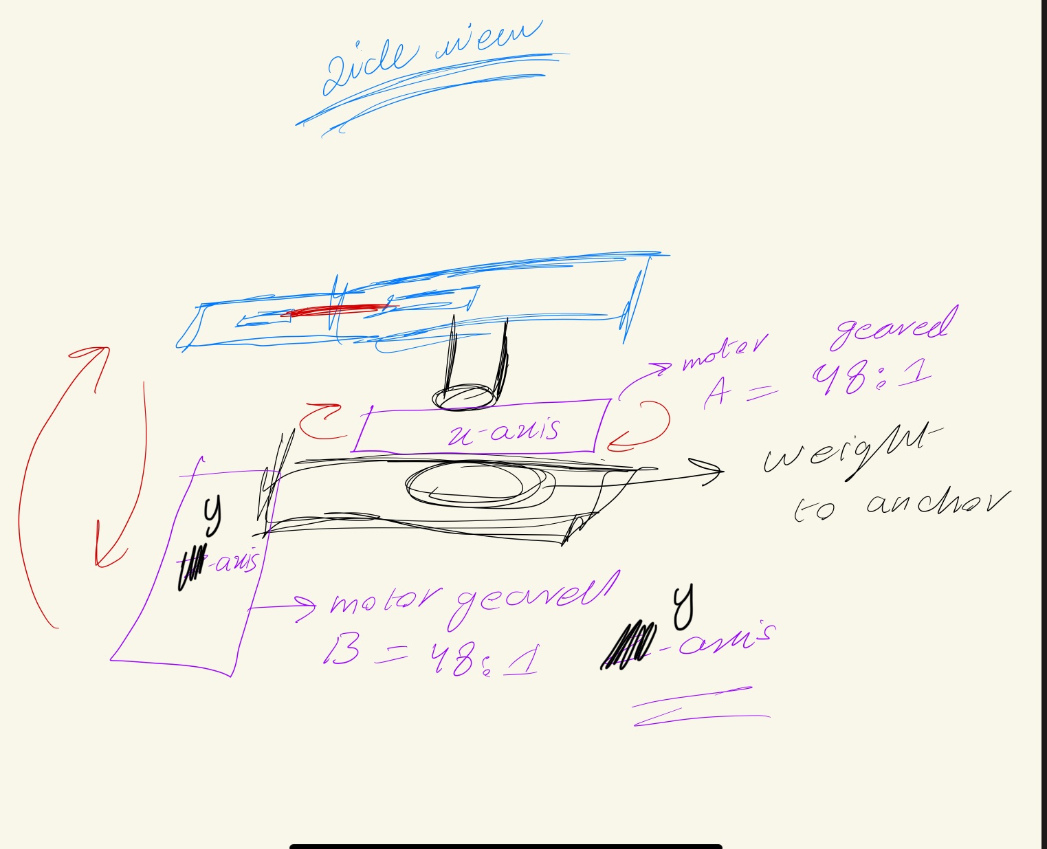
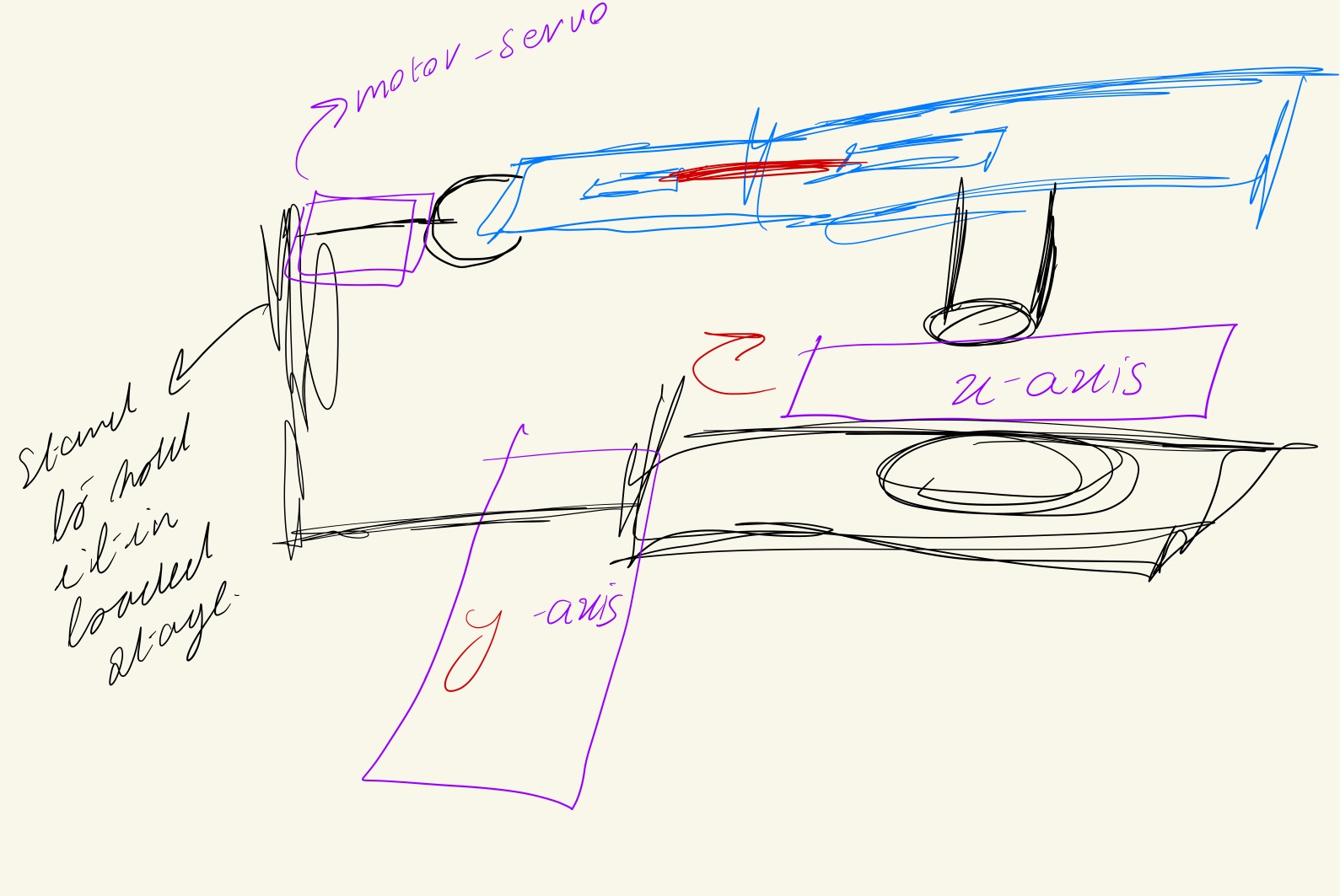
Since the weight of the whole thing only kept on increasing, the efficiency was to avoid y-axis movement, and instead go for vertical acceleration and a projectile motion.

Projectile Motion For Vertical Velocity | GeeksforGeeks

Last but not the least, wooden pieces from IM lab were used alongside wheels and a 48:1 gear motor for turning the launcher within the horizontal axis.

The final assembled project looks something like this:

Motor driver was added to regulate and power the voltage being drawn from Arduino towards the geared motor.

Arduino and P5 Code:

Arduino:

The arduino code has pin mapped out. The motor driver receives PWM signal from


const int ain1Pin = 3;
const int ain2Pin = 4;
const int pwmPin = 5;
int score = 0;

const int startButton = A0;
const int greenButton = A1;
const int redButton = A3;
const int trigger = A5;

const int greenLED = 12;
const int redLED = 8;
const int blueLED = 7;

int trigVal = 0;
const int threshold = 400;

enum GameState { MENU, GAMEPLAY, PAUSED };
GameState gameState = MENU;

void setup() {
  Serial.begin(9600);

  pinMode(ain1Pin, OUTPUT);
  pinMode(ain2Pin, OUTPUT);
  pinMode(pwmPin, OUTPUT);

  pinMode(greenLED, OUTPUT);
  pinMode(redLED, OUTPUT);
  pinMode(blueLED, OUTPUT);

  digitalWrite(redLED, HIGH);
  digitalWrite(greenLED, LOW);
  digitalWrite(blueLED, LOW);

  delay(500);
}

void loop() {
  int startVal = analogRead(startButton);
  int greenVal = analogRead(greenButton);
  int redVal = analogRead(redButton);
  trigVal = analogRead(trigger);

  static bool lastStartPressed = false;
  static bool lastTriggerPressed = false;

  bool startPressed = startVal > threshold;
  bool triggerPressed = trigVal > 1020;

  // Serial communication from p5.js
  if (Serial.available() > 0) {
    String message = Serial.readStringUntil('\n');
    message.trim();

    if (message == "HELLO") {
      Serial.println("ACKNOWLEDGED");
    } else if (message == "RESET") {
      gameState = MENU;
      digitalWrite(redLED, HIGH);
      digitalWrite(greenLED, LOW);
      digitalWrite(blueLED, LOW);
      digitalWrite(ain1Pin, LOW);
      digitalWrite(ain2Pin, LOW);
      analogWrite(pwmPin, 0);
    } else if (message == "Game over") {
      // Optional cleanup
    }
  }

  // Handle start button press
  if (startPressed && !lastStartPressed) {
    if (gameState == MENU) {
      Serial.println("Starting game!");
      gameState = GAMEPLAY;

      digitalWrite(redLED, LOW);
      digitalWrite(greenLED, HIGH);
      digitalWrite(blueLED, LOW);

      digitalWrite(ain1Pin, LOW);
      digitalWrite(ain2Pin, LOW);
      analogWrite(pwmPin, 0);
    }
    else if (gameState == GAMEPLAY) {
      Serial.println("Game paused!");
      gameState = PAUSED;

      digitalWrite(greenLED, LOW);
      digitalWrite(blueLED, HIGH);

      digitalWrite(ain1Pin, HIGH);
      digitalWrite(ain2Pin, HIGH);
      analogWrite(pwmPin, 255);
    }
    else if (gameState == PAUSED) {
      Serial.println("Resuming game!");
      gameState = GAMEPLAY;

      digitalWrite(greenLED, HIGH);
      digitalWrite(blueLED, LOW);

      digitalWrite(ain1Pin, LOW);
      digitalWrite(ain2Pin, LOW);
      analogWrite(pwmPin, 0);
    }
  }
  lastStartPressed = startPressed;

  // Score trigger: rising edge detection
  if (gameState == GAMEPLAY && triggerPressed && !lastTriggerPressed) {
    score++;
    Serial.print("SCORE:");
    Serial.println(score);
  }
  lastTriggerPressed = triggerPressed;

  // Motor control during gameplay
  if (gameState == GAMEPLAY) {
    if (greenVal > threshold) {
      Serial.println("Green button pressed - motor right");
      digitalWrite(ain1Pin, LOW);
      digitalWrite(ain2Pin, HIGH);
      analogWrite(pwmPin, 255);
    }
    else if (redVal > threshold) {
      Serial.println("Red button pressed - motor left");
      digitalWrite(ain1Pin, HIGH);
      digitalWrite(ain2Pin, LOW);
      analogWrite(pwmPin, 255);
    }
    else {
      digitalWrite(ain1Pin, LOW);
      digitalWrite(ain2Pin, LOW);
      analogWrite(pwmPin, 0);
    }
  }
}

P5:

let rVal = 0;
let alpha = 255;
let gameState = 'MENU';  // 'MENU', 'GAMEPLAY', 'RESULT', 'WAITING_FOR_START'
let counter = 60;
let points = 0;
let score = 0;


let left = 0;
let right = 0;

let resultTimer = 0;


function setup() {
  createCanvas(640, 480);
  textAlign(CENTER, CENTER);
  textSize(24);
}

function draw() {
  background(map(rVal, 0, 1023, 0, 255), 255, 255);

  fill(255, 0, 255, map(alpha, 0, 1023, 0, 255));
  // text("Game State: " + gameState, 20, 30);

  if (gameState === 'MENU') {
    resultTimer = 0;
    showMenuScreen();
  } else if (gameState === 'WAITING_FOR_START') {
    showWaitingScreen();
  } else if (gameState === 'GAMEPLAY') {
    showGameScreen();
  } else if (gameState === 'RESULT') {
    showResultScreen();
    resultTimer++;
    if (resultTimer === 180) { // ~3 seconds
      writeSerial("RESET\n");
      gameState = 'MENU';
    }
  }

  if (mouseIsPressed) {
    if (mouseX <= width / 2) {
      left = 1;
    } else {
      right = 1;
    }
  } else {
    left = right = 0;
  }
}

function readSerial(data) {
  data = trim(data);

  // Start game and reset counter and points
  if (data === "Starting game!") {
    counter = 60;
    points = 0;
    gameState = 'GAMEPLAY';
    return;
  }

  // Check if the data contains the score information
  if (data.startsWith("SCORE:")) {
    points = int(data.split(":")[1]);  // Extract score from Arduino message
    return;
  }

  // Process rVal and alpha from Arduino (existing logic)
  let fromArduino = split(data, ",");
  if (fromArduino.length === 2) {
    rVal = int(fromArduino[0]);
    alpha = int(fromArduino[1]);
  }

  // Send button press information back to Arduino
  let sendToArduino = left + "," + right + "\n";
  writeSerial(sendToArduino);
}
 

function showMenuScreen() {
  fill(0);
  textSize(32);
  text("Project Clean Shot", width / 2, height / 2 - 50);
  textSize(24);
  text("Press Space Bar to Start Communication", width / 2, height / 2);
}

function showWaitingScreen() {
  fill(0);
  textSize(28);
  text("Waiting for Arduino to start the game...", width / 2, height / 2);
}

function showGameScreen() {
  fill(0);
  textSize(64);
  text(counter, width / 2, height / 2 - 50);
  textSize(32);
  text("Points: " + points , width / 2, height / 2 + 50);

  if (frameCount % 60 === 0 && counter > 0) {
    counter--;
  }

  if (counter <= 0) {
    gameState = 'RESULT';
    writeSerial("Game over\n");
  }
}

function showResultScreen() {
  fill(0);
  textSize(48);
  text("Game Over", width / 2, height / 2 - 50);
  textSize(32);
  text("Points: " + points, width / 2, height / 2);
  textSize(24);
  text("Returning to Menu...", width / 2, height / 2 + 50);
}

function keyPressed() {
  if (key === " " && gameState === 'MENU') {
    setUpSerial(); // comes from the serial adapter file
    gameState = 'WAITING_FOR_START';
  }
}

P5 Demo link:  https://editor.p5js.org/alinoor_3707/sketches/QbmSLt2kR

P5 and Arduino communication:

P5 and Arduino both communicate using serial mode of communication, which via the USB communicates to one another. The Arduino for instance in our case, after measuring physical values, generates digital signal in the form of ‘Serial.println’ for instance. This is then read by P5js using the web serial API. Since I couldn’t attend the earlier class where this was discussed, I had a hard time understanding the working, and ended up venturing into the NodeJS based p5Serial software after watching an outdated tutorial online. It was after close-reading the documentation that I realized that there is a web-based serial communication interface as well. Nonetheless, using p5.web-serial the data was read. Hence, the Arduino would write and the P5 program would listen. It is; however, working other way around as well when the timer ends and the arduino is told to change the state from gameplay to menu.

Description of interactivity:

The main focus and area of attention was the hardware. 30 percent of time was dedicated to P5 based interaction and majority of the rest was dedicated to Arduino and mechanism behind the rotation and launch of the barrel. The idea was to build a tangible and sturdy structure i.e responsive. Borrowing the idea from one of the readings: A Brief Rant on the Future of Interaction Design,  I wanted to build something that was not hidden underneath the glass-screen as the author described it, but was tactile and tangible in nature.
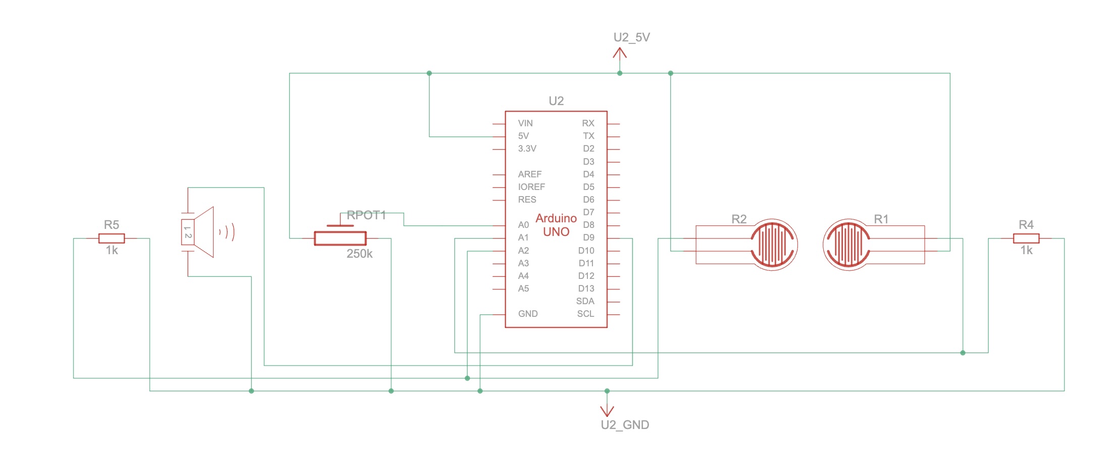
Circuit schematic:

For the circuitry, since a motor was incorporated to handle the horizontal movement, this time I referred to the tutorial notes provided by Professor Shiloh alongside the sketch for the schematic:

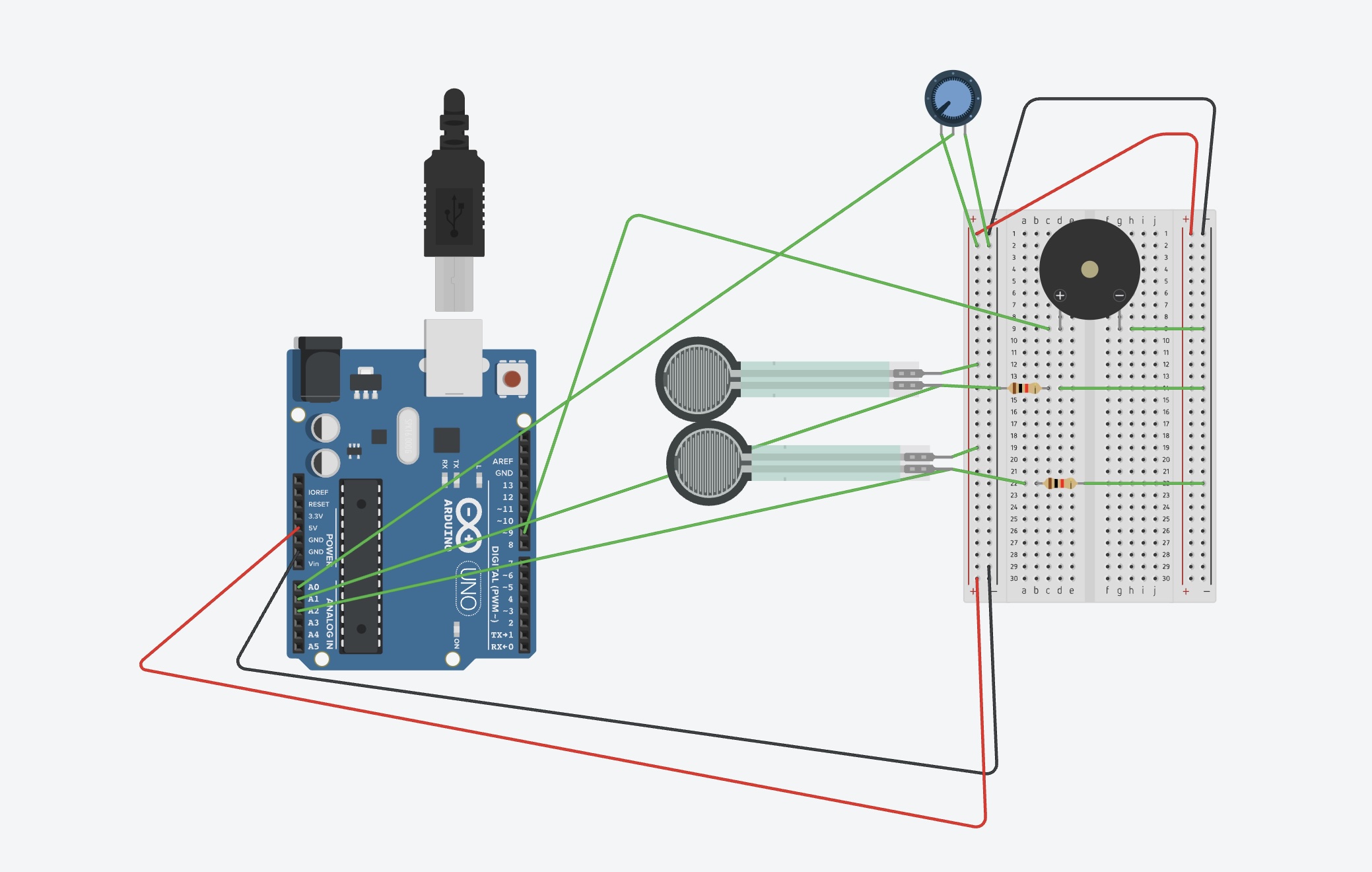
After mapping and implementing this sketch, the next matter at hand was the implementation of the Buttons and LEDs, which were done after first drafting a sketch:

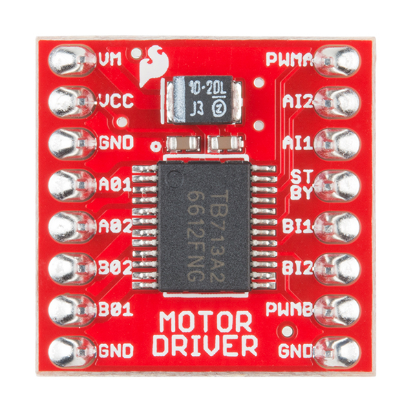
NOTE: Since the Sparkfun TB6612 FNG motor driver wasn’t available in drawing tool, so an alternative has been used to refer to the mapping of the one used.

The sketch digram:

Aspect I am proud of:

The best and most favorite part that makes me happy to get done with was the crafting and hacking. There was a temptation to tinker around with the New Prusa 3-D printers inside the IM lab, however, in the spirit of craftmanship, and getting hands dirty, I decided to drill, saw, cut, glue, sand, break, and do all sorts of wonderful things. It was a crash-course, but I am now much more confident in my ability to build things, instead of placing order to 3rd party contractors to build stuff. This makes me immensely proud of myself and the thing I built with my hand – no matter the imperfections.

Areas for future improvement:

One of the areas that I did work on, but didn’t end up working was the latch mechanism for triggering the release of the barrel after it had been loaded. It popped off due to high tension in the rubber-bands/ elastic, and due to weak structural integrity of the launcher. In the future I would like to work with techniques that help avoid loose fittings and things breaking off.

Moreover, I wanted to add haptics and gyroscope, however, having limited experience with the sensor and low on time, I decided to go with tactile buttons. In the future I would like to work on response hand-gesture controlled mechanism, which also works in the y-axis with an additional motor!

Week 11 – Production assignment + Preliminary concept

Production Assignment

Introduction:

This assignment had us learn and implement serial communication between Arduino and P5.js. The conversation could be one direction or bi-directional. The script and additional web-based API, provided by NYU’s I.M faculty was used to implement concept, which utilized Arduino and P5.js.

Schematic and Wiring:

The sketch for the wiring and connections.

Schematic for the Arduino connection and port mapping

For this assignment, potentiometer was used for adjusting the vertical affects of the wind. The FSR – Force Sensitive Resistor was used to move the ball horizontally. Depending on the pressure, you would have rightward movement. For the LED in the middle, that was used to indicate impact with the surface. Hence would light up whenever the ball would bounce. As for the right most LED, it would light up, when the button on P5.JS was triggered, i.e increase the brightness. The port-mapping and pin assignment are visible on both the sketch, as well as the schematic.

P5 project and code:

let fsrVal = 0;
let potVal = 0;

let led1Brightness = 0; 
let bounceFlag = 0;

let position, velocity, acceleration, gravity, wind;
let drag = 0.99;
let mass = 50;
let prevBounce = false;

let button;

function setup() {
  createCanvas(640, 360);
  position = createVector(width / 2, 0);
  velocity = createVector(0, 0);
  acceleration = createVector(0, 0);
  gravity = createVector(0, 0.5 * mass);
  wind = createVector(0, 0);

  button = createButton('Increase Brightness');
  button.position(10, height + 10);
  button.mousePressed(() => {
    led1Brightness = (led1Brightness + 200) % 256;
  });
}

function draw() {
  background(255);

  // ========== Task 1: move ellipse horizontally using FSR only ==========
  let xMapped = map(fsrVal, 0, 1023, 50, width - 50);
  position.x = xMapped;

  // ========== Task 3: adjust gravity based on potentiometer ==========
  let gravityScale = map(potVal, 0, 1023, 0.1, 0.5);
  gravity.y = gravityScale * mass;

  applyForce(wind);
  applyForce(gravity);
  velocity.add(acceleration);
  velocity.mult(drag);
  position.add(velocity);
  acceleration.mult(0);

  ellipse(position.x, position.y, mass, mass);

  // ========== Bounce Logic ==========
  let isBouncing = false;
  if (position.y > height - mass / 2) {
    velocity.y *= -0.9;
    position.y = height - mass / 2;
    isBouncing = true;
  }

  // Detect rising edge (bounce just occurred)
  bounceFlag = isBouncing && !prevBounce ? 1 : 0;
  prevBounce = isBouncing;

  // ========== Serial send ==========
  if (serialActive) {
    let sendToArduino = led1Brightness + "," + bounceFlag + "\n";
    writeSerial(sendToArduino);
  }

  // Debugging values
  fill(0);
  text(`FSR: ${fsrVal}`, 10, 20);
  text(`Pot: ${potVal}`, 10, 40);
  text(`LED Brightness: ${led1Brightness}`, 10, 60);
}

function applyForce(force) {
  let f = p5.Vector.div(force, mass);
  acceleration.add(f);
}

function keyPressed() {
  if (key == " ") {
    setUpSerial();
  }
  
   if (key === 'l' || key === 'L') {
    velocity.y = -10; // Negative Y velocity = upward bounce
  }
}

// Serial reading
function readSerial(data) {
  if (data != null) {
    let fromArduino = split(trim(data), ",");
    if (fromArduino.length === 2) {
      fsrVal = int(fromArduino[0]);
      potVal = int(fromArduino[1]);
    }
  }
}


/*
int fsrPin = A0;        // Task 1 - Move ellipse
int led1Pin = 3;        // Task 2 - LED controlled by p5.js button (PWM)
int potPin = A2;        // Task 3 - Gravity control
int led2Pin = 5;        // Task 3 - Blink on bounce (PWM)

int led1Brightness = 0;
bool bounceFlag = false;

void setup() {
  Serial.begin(9600);
  pinMode(LED_BUILTIN, OUTPUT);
  pinMode(led1Pin, OUTPUT);
  pinMode(led2Pin, OUTPUT);

  // Initial blink
  digitalWrite(led1Pin, HIGH);
  digitalWrite(led2Pin, HIGH);
  delay(200);
  digitalWrite(led1Pin, LOW);
  digitalWrite(led2Pin, LOW);

  while (Serial.available() <= 0) {
    digitalWrite(LED_BUILTIN, HIGH);
    Serial.println("0,0");
    delay(300);
    digitalWrite(LED_BUILTIN, LOW);
    delay(50);
  }
}

void loop() {
  while (Serial.available()) {
    digitalWrite(LED_BUILTIN, HIGH);
    int led1Val = Serial.parseInt();       // brightness from p5.js (0–255)
    int bounce = Serial.parseInt();        // whether ball bounced (1 or 0)
    if (Serial.read() == '\n') {
      analogWrite(led1Pin, led1Val);
      if (bounce == 1) {
        digitalWrite(led2Pin, HIGH);
        delay(50);
        digitalWrite(led2Pin, LOW);
      }

      int fsrVal = analogRead(fsrPin);
      int potVal = analogRead(potPin);
      Serial.print(fsrVal);
      Serial.print(",");
      Serial.println(potVal);
    }
  }
  digitalWrite(LED_BUILTIN, LOW);
}


*/

In addition to code provided by Professor Mang and Sherwood, some implementations were done such as ‘key-press’ function utilizing letter ‘l’ or ‘L’ to make the ball bounce again for the demonstration and as for the port mappings, they have been commented out and labelled inside the code.

Arduino code:

int fsrPin = A0;        // Task 1 - Move ellipse
int led1Pin = 3;        // Task 2 - LED controlled by p5.js button (PWM)
int potPin = A2;        // Task 3 - Gravity control
int led2Pin = 5;        // Task 3 - Blink on bounce (PWM)

int led1Brightness = 0;
bool bounceFlag = false;

void setup() {
  Serial.begin(9600);
  pinMode(LED_BUILTIN, OUTPUT);
  pinMode(led1Pin, OUTPUT);
  pinMode(led2Pin, OUTPUT);

  // Initial blink
  digitalWrite(led1Pin, HIGH);
  digitalWrite(led2Pin, HIGH);
  delay(200);
  digitalWrite(led1Pin, LOW);
  digitalWrite(led2Pin, LOW);

  while (Serial.available() <= 0) {
    digitalWrite(LED_BUILTIN, HIGH);
    Serial.println("0,0");
    delay(300);
    digitalWrite(LED_BUILTIN, LOW);
    delay(50);
  }
}

void loop() {
  while (Serial.available()) {
    digitalWrite(LED_BUILTIN, HIGH);
    int led1Val = Serial.parseInt();       // brightness from p5.js (0–255)
    int bounce = Serial.parseInt();        // whether ball bounced (1 or 0)
    if (Serial.read() == '\n') {
      analogWrite(led1Pin, led1Val);
      if (bounce == 1) {
        digitalWrite(led2Pin, HIGH);
        delay(50);
        digitalWrite(led2Pin, LOW);
      }

      int fsrVal = analogRead(fsrPin);
      int potVal = analogRead(potPin);
      Serial.print(fsrVal);
      Serial.print(",");
      Serial.println(potVal);
    }
  }
  digitalWrite(LED_BUILTIN, LOW);
}

Demo Video:

Video Demo

In the video, the FSR is used to move the ball on the X-axis i.e task 1. The potentiometer value, which is set to zero, is tuned up. When it increases, the vertical wind pressure makes the bounce and rebound lower. Nonetheless, whenever it bounces, the red LED in the middle lights up i.e task 3. Using P5.js, the brightness can be adjusted, which is demonstrated and visualized through the LED on the right-most side.

Challenges:

Since I was in the hospital, couldn’t get to team up with anyone, missed out on the lecture, it was extremely hard to configure and understand the serial communication between P5.js and Arduino. Nonetheless, after going on and on, again and again over Professor Shiloh’s notes, I finally got it to work.

The tutorials online had a software that used node.js for the communication. A misdirection which costed me my time and energy. Took forever to debug. Since my classmates were busy and I had everything piled up, getting it done on time was hard. Nonetheless, managed to do so. As for the other challenges, the LED light for increase in Brightness was initially green. It wouldn’t increase in brightness significantly, which led me to suspect issue with the code. After much time spent, it was realized that that LED despite working, for some-reason didn’t respond to the PWM signals as accurately as the RED one. So, it was swapped with the RED LED.

Preliminary Concept for the final Project

The concept for the final project kept on varying from a robotic soccer leg ( discussed with Professor Aya) to a prosthetic hand, which was discussed in detail with Professor Shiloh. The final project as of now remains unclear. I do want to make something crazy and go all out. Currently I think of something that involves me reusing and crafting from scratch by reusing already available materials (hacking). Hence, something which fits a perfect balance between hardware, and soft-logic. Something that makes use of all of the concepts (or most of them), which were learnt inside the class.


Week 11 – Reading Response

Design Meets Disability

Reading opens up with the example of a leg splint, and how contrary to the ‘trickle-down’ effect, we have the design for a small segment or portion of the community being inducted into the mainstream industry. The argument is made surrounding the example of prosthetics or aids for differently abled people, which are designed to camouflage and blend in, as if it is a shame to use them in the first place. The reading discusses how there is a tension between the two concepts of presentation and concealment, and how it is difficult to provide both. Solid examples such as eyewear are provided where “from medical necessity into key fashion accessory” the transition was made, despite entities like the NHS opting for transparent frames to make it less noticeable.

The case of hearing aids and game-changer HearWear was also made. Throughout the reading, the emphasis was put on the concept of design, and how the effort and energy put into it is crucial to the performance of the product. An instance of this can be the example of prosthetics, which, being different in nature as they are an extension of one’s body part, are designed in a way to be both functional and socially pleasing. However, the designing  element when it comes to looks and feel is not credited enough, and people behind such are snubbed. Now, the author doesn’t use the word “ snub” directly, but personally it can be agreed that this area or line of work isn’t commended much. Although, this isn’t the case all of the time. The case of the iPod differs. With its small design and portability, it not only revolutionized the tech industry in terms of its performance but also set a bar when it came to design and aesthetics – gathering different accolades and awards in this segment.

After having read, it was imperative to draw a connection with a similar concept discussed in the previous reading, on how the design aesthetics make even the most complicated systems in terms of their operability, appear to be perceived as easy to work with thanks to their design and interactivity component. However, it is also the case that sometimes, in certain cases, the functionality and usability are sacrificed to what the eye truly beholds as worthwhile, whereas the mind deems it to be a misfit. As mentioned in the reading ‘Attractive Things Work Better’, objects like impossible teapots stand out in terms of fashion/decorative statement, but lack usefulness. Personally, I believe that through the outward statement made by products such as hearing aids, the public perception towards differently abled can be neutralized. Instead of miniturizing aids to reduce visibility and lose out on functional efficiency due to small size, why not give up concealment and improve the usefulness? I certainly believe that design and engineering both go hand-in-hand. Like peanut butter and jelly inside of a sandwich. Therefore, being a crucial component, concealment in such cases should be dealt with the idea of ‘presentation’.

However, I also believe that exaggeration in terms of design should be avoided. In the pursuit of making a fashion statement, the redundancy and unnecessary patterns can be introduced. Therefore, it is equally important to attain equilibrium between the adequate design and functionality.

Week 10 – Reading

The web article entitled “A Brief Rant on the Future of Interaction Design” evokes a range of emotions in its readers. Initially, the video produced by Microsoft appeared flawless and aligned with the reader’s expectations of the future. However, the subsequent discussion on tools and interaction components prompted a reevaluation of what constitutes an improvement. The author effectively illustrates this point by comparing a hammer to human interaction, emphasizing that our hands are the primary component in tangible interactions. The author argues that despite the underlying technology, our interactions have slightly improved. This argument is supported by the concept of “tactile richness.”

While I generally agree with the author’s assertion that corporations often exaggerate the advancements in their products, I find the notion that tactile richness can be fully extracted from non-tangible elements to be flawed. Furthermore, the development of haptics and sensors like gyroscopes has enabled the creation of products such as smart glass, which have revolutionized human-computer interaction by incorporating gestures like head tilts, voice commands, and other active inputs. These advancements significantly surpass the limitations of traditional touchscreens. Consequently, I believe they contradict the author’s claim that tangible improvements are not being made.

Nevertheless, I acknowledge that in terms of manipulation and tactile richness, the emphasis on branding and hype may not accurately reflect the actual level of advancement.

Regarding the other reading, it sent me into a frenzy full of laughter. The majority of the disagreements and counterarguments I had, such as the use of gestures, voice, and tangible-non-tangible elements, were addressed in this follow-up response. I acknowledge that the writer possesses a distinct perception and perspective, and how they employ certain claims to support their arguments, such as densely nerve-covered finger tips and their correlation with brain development. However, I firmly believe that it ultimately reduces to the concept of interpretivism. How we define technology. For someone completely unfamiliar with the concept of a stylus, they would likely find little to utilize or develop with. In their eyes, a transition from a stylus to an OLED glass display would appear more advantageous and innovative. Personally, I grew up with a Nintendo DS that came with a stylus. The next generation of PS-Vita captured my attention, and since then, I have never touched that Nintendo. The tool we use to amplify certain phenomena—for some, the desired amplification may vary. Therefore, I firmly believe that our responses differ. Furthermore, considering the significant advancements in technology since the publication of this article fourteen years ago, I suspect that the author may simply be making certain exceptions.

Week 10 – Production Assignment

Musical Instrument

Introduction:

An instrument is something that helps us humans either measure the data or produce it. For this assignment, we were supposed to build a musical instrument in a group of two. Given my health challenges, I was unable to team up with anyone, and decided to pursue it on my own. I started off by asking the most fundamental question – “What is a musical instrument ? ” Something that plays sound when triggered? Or something that plays sound on its own? What kind of sound? How many sounds? It is when after pondering on the philosophy of a musical device, I questioned my surroundings. I don’t happen to have a dorm mate, and very less likely do I get to socialize with others around the campus. Sometimes the thoughts themselves get too loud that I start second guessing my self. This is where the eureka moment came in! A musical device that talks to me – interacts with my as if a roommate for instance would have done. To start off with basics, a greeting or a salutation would have had sufficed as well. There and then the idea of ‘Welcominator’ was born!

Concept and design:

After having decided upon what to make and accomplish, I got down to work. The basic logic of ‘Welcominator’ would involve use of a trigger mechanism which would recognize the moment I settle inside my room, and a speaker, alongside a digital and an analogue switch to trigger and adjust response.

For the digital sensor / switch I decided to use the FSR sensor (Force Sensing Resistor). This sensor reduces the resistance with greater pressure applied, and by logic qualifies for the analogue sensor. However, the basic concept to this instrument was me putting down my items such as my watch as soon as I enter and settle down inside my dorm. Thus, two FSR sensors were used for greater surface area, and the value read by these sensors was read using digitalRead. Therefore, acting as a switch, the value of 1 or 0 was only read.

As for the analogue sensor, the potentiometer was used. The potentiometer in this case was not used to adjust the volume, but rather to choose between the audio tracks. The code written would select which sound to play depending on the current fed in by the wiper toward the A0 pin on the Arduino. The schematic and sketch below show the connection and logical mapping of the ciruit:


The buzzer or the speaker takes voltage signals from pin 9, whilst the digitalRead performed on FSR sensor is sent to pin A1 and A2 respective of the sensor.  It is an active buzzer and hence can play different sound tunes.

Code:

//crucial file added to understand how pitches and notes work
#include "pitches.h"

#define BUZZER_PIN 9
#define POT_PIN A0
#define SENSOR1_PIN A1
#define SENSOR2_PIN A2

bool isPlaying = false;

// godfather
int godfather_melody[] = {
  NOTE_E4, NOTE_A4, NOTE_C5, NOTE_B4, NOTE_A4, NOTE_C5, NOTE_A4, NOTE_B4, NOTE_A4, NOTE_F4, NOTE_G4,
  NOTE_E4, NOTE_E4, NOTE_A4, NOTE_C5,
  NOTE_B4, NOTE_A4, NOTE_C5, NOTE_A4, NOTE_C5, NOTE_A4, NOTE_E4, NOTE_DS4,
  NOTE_D4, NOTE_D4, NOTE_F4, NOTE_GS4,
  NOTE_B4, NOTE_D4, NOTE_F4, NOTE_GS4,
  NOTE_A4, NOTE_C4, NOTE_C4, NOTE_G4,
  NOTE_F4, NOTE_E4, NOTE_G4, NOTE_F4, NOTE_F4, NOTE_E4, NOTE_E4, NOTE_GS4,
  NOTE_A4
};

int godfather_durations[] = {
  8, 8, 8, 8, 8, 8, 8, 8, 8, 8, 8,
  2, 8, 8, 8,
  8, 8, 8, 8, 8, 8, 8, 8,
  2, 8, 8, 8,
  2, 8, 8, 8,
  2, 8, 8, 8,
  8, 8, 8, 8, 8, 8, 8, 8,
  2
};

// nokia tune
int nokia_melody[] = {
  NOTE_E5, NOTE_D5, NOTE_FS4, NOTE_GS4, 
  NOTE_CS5, NOTE_B4, NOTE_D4, NOTE_E4,
  NOTE_B4, NOTE_A4, NOTE_CS4, NOTE_E4,
  NOTE_A4
};

int nokia_durations[] = {
  8, 8, 8, 8,
  8, 8, 8, 8,
  8, 8, 8, 8,
  8
};


void setup() {
  pinMode(BUZZER_PIN, OUTPUT);
  pinMode(SENSOR1_PIN, INPUT);
  pinMode(SENSOR2_PIN, INPUT);
  pinMode(POT_PIN, INPUT);
}


void loop() {
  int potValue = analogRead(POT_PIN);
  bool useGodfather = potValue < 512;  // Left side (low) pot = Godfather, Right (high) = Nokia

  int sensor1Value = digitalRead(SENSOR1_PIN);
  int sensor2Value = digitalRead(SENSOR2_PIN);

  bool sensorTriggered1 = sensor1Value == HIGH;
  bool sensorTriggered2 = sensor2Value == HIGH;

  if ((sensorTriggered1 || sensorTriggered2) && !isPlaying) { // checks if no music is playing and either of the sensor trigger is recorded for
    isPlaying = true;
    if (useGodfather) {
      playMelody(godfather_melody, godfather_durations, sizeof(godfather_melody) / sizeof(int));
    } else {
      playMelody(nokia_melody, nokia_durations, sizeof(nokia_melody) / sizeof(int));
    }
    isPlaying = false;
  }
}

//function for playing melody
void playMelody(int melody[], int durations[], int length) {
  for (int i = 0; i < length; i++) {
    int noteDuration = 1000 / durations[i];
    tone(BUZZER_PIN, melody[i], noteDuration);
    delay(noteDuration * 1.2); // time duration added betnween notes to make it seem buttery smooth.
    noTone(BUZZER_PIN);
  }
}
// pitches.h
#define REST 0

#define NOTE_B0 31
#define NOTE_C1 33
#define NOTE_CS1 35
#define NOTE_D1 37
#define NOTE_DS1 39
#define NOTE_E1 41
#define NOTE_F1 44
#define NOTE_FS1 46
#define NOTE_G1 49
#define NOTE_GS1 52
#define NOTE_A1 55
#define NOTE_AS1 58
#define NOTE_B1 62
#define NOTE_C2 65
#define NOTE_CS2 69
#define NOTE_D2 73
#define NOTE_DS2 78
#define NOTE_E2 82
#define NOTE_F2 87
#define NOTE_FS2 93
#define NOTE_G2 98
#define NOTE_GS2 104
#define NOTE_A2 110
#define NOTE_AS2 117
#define NOTE_B2 123
#define NOTE_C3 131
#define NOTE_CS3 139
#define NOTE_D3 147
#define NOTE_DS3 156
#define NOTE_E3 165
#define NOTE_F3 175
#define NOTE_FS3 185
#define NOTE_G3 196
#define NOTE_GS3 208
#define NOTE_A3 220
#define NOTE_AS3 233
#define NOTE_B3 247
#define NOTE_C4 262
#define NOTE_CS4 277
#define NOTE_D4 294
#define NOTE_DS4 311
#define NOTE_E4 330
#define NOTE_F4 349
#define NOTE_FS4 370
#define NOTE_G4 392
#define NOTE_GS4 415
#define NOTE_A4 440
#define NOTE_AS4 466
#define NOTE_B4 494
#define NOTE_C5 523
#define NOTE_CS5 554
#define NOTE_D5 587
#define NOTE_DS5 622
#define NOTE_E5 659
#define NOTE_F5 698
#define NOTE_FS5 740
#define NOTE_G5 784
#define NOTE_GS5 831
#define NOTE_A5 880
#define NOTE_AS5 932
#define NOTE_B5 988
#define NOTE_C6 1047
#define NOTE_CS6 1109
#define NOTE_D6 1175
#define NOTE_DS6 1245
#define NOTE_E6 1319
#define NOTE_F6 1397
#define NOTE_FS6 1480
#define NOTE_G6 1568
#define NOTE_GS6 1661
#define NOTE_A6 1760
#define NOTE_AS6 1865
#define NOTE_B6 1976
#define NOTE_C7 2093
#define NOTE_CS7 2217
#define NOTE_D7 2349
#define NOTE_DS7 2489
#define NOTE_E7 2637
#define NOTE_F7 2794
#define NOTE_FS7 2960
#define NOTE_G7 3136
#define NOTE_GS7 3322
#define NOTE_A7 3520
#define NOTE_AS7 3729
#define NOTE_B7 3951

The code above addresses the logic and the pitches.h is another file used for defining and storing the notes that are used by our program. Code for the pitches and the sounds for ‘Godfather theme’ and ‘Nokia ‘ tune were taken from Arduino Project HUB website .

Both FSR sensor trigger HIGH or LOW value, and if potentiometer is registering lower voltage, then Godfather theme plays, and when it registers higher voltage, the Nokia tune plays. Once it ends, it sets the isPlaying state to false. This is to avoid interruption. Last but not the least, chatgpt was used to order pitches.h file as coding it myself would have been impossible.


Challenges:

One and the only challenge I faced was the FSR registering high, even when there was no pressure being applied. This led me to do some researching. Turns out that sometimes inaccuracy and condition of the sensor renders false positives. Hence, I used a resistor connection with the sensor and ground to get rid of the  tingling current, and register high only when a solid threshold was provided. An led was attached before the buzzer, for visual aesthetics and for indication that current was going through the buzzer. Initially the buzzer would work as well. This led me to code and find the bug in wrong pin assignment

Demo:

Future Revisions:

For future revision I intend to add multiple songs, FSR sensors, and an array of leds which can mimic the sound pattern.

Week 12 – Final Project Proposal : Canon Powered Cornhole Game

Introduction:

Growing up in a South Asian country, I consumed American Media – films,  documentaries, comedy skits, and even FOX News for my daily dose of reliable news. It was during this time that I happened to have been introduced to the carnival game of ‘Cornhole’  during a KSN-TV’s broadcast on Kansas country-side fair. A mix of basketball and golf with a southern dialect to it – I found it to be fascinating. It was so fascinating that when I was overwhelmed by so many ideas to choose from for this final project, I decided to go with a ‘Canon Powered’ Cornhole Game. Instead of tossing by hand, participants decide orientation in X and Y axis, and let the canon shoot out the corn bag. In our case, it would be a small sack filled with weight.


Amazon.com : Super Fun, Portable Mini Desktop Cornhole Set of 2. Coated Wood Boards with 4 Red 4 Blue Bags. Gift for Students, Office Employees or Work from Home. Simple Easy Tabletop

Canon:

The canon would be a 3d printed model. Not big, just about big as my Week 9’s canon. Yes, this is a continuation of that project! That was a candy canon that moved in X axis. This is a fully functional canon with loading and reloading capabilities!

The sketches below visualizes the working and highlights the basic design of the canon. The first one shows how to concept is imagined to be. The canon releases the inside barrel powered by an elastic material having stored the elastic potential energy. That potential energy is released and converted into kinetic energy. This kinetic energy and speed coupled with momentum results in impulse provided to the sack which turns its inertia to a trajectory.

The side view demonstrates the use of two motors, one oriented for x-axis movement and the other one for y-axis movement.

The supported stand on the left end with a claw-like  grappler helps keep the canon loaded. Upon trigger, it will release and let the tension of the elastic loose which will lead to forward release mechanism.

Arduino and P5 Program :

The movement of this canon will be controlled by gyroscope mounted on to gym-gloves. The gloves will also have the flex sensors, so that with hand tilt and movement, corresponding movement along x and y-axis will take place. When the hands are clenched , it will result to the release mechanism being triggered. A pressure sensor will be put underneath the hole/target to detect if the ball/sack has landed. The p5 program will first start off with a menu with  screen offering the user to play or go over instructions. This game will be both in virtual and real domain. The game will start with a 1 minute counter. For each corn in the hole, user will get response on the screen with animation and led will light up, while also points would increase.  When in reload state, the user won’t be able to move the robot, this is for convenience as to prevent user from mistakenly moving the robot while reloading. Once the game ends, the robot stops moving and the highscore displayed.

The arduino will control the movement of the three motors as an output signal (PWM), with last one being a servo, it will take input from the gyroscope and flex sensor for the controls. The Pressure sensor under the cornhole will trigger point system and this will be conveyed to the P5  program by and  after having read by the Arduino. The state of servo motor will be conveyed to the p5 program as well. In return, the p5 will communicate back the permission or the kill-switch condition to start or stop the program. It will process and display the state (i.e launch or reload), and will show the points alongside the timmer. I will add in safety nets too to prevent the machine from turning too much and breaking the structure/casing. Last but not the least, it will shutdown the connection between the gloves and the motors once the game has concluded.

Week 9 – Reading

Physical Computing’s Greatest hits and misses:

The author mentions recurring themes of projects that are showcased every-year. While reading, I wondered what physical computing really is to begin with in the first place. After going through the reading and googling it up, it turns out to be the combination of hardware and software. A mix of the tangible and the non-tangible computational elements. The main agenda or concept the author was trying to get across the board was to never give-up despite the commonality of the theme of ideas that students usually come up with. Within the same domain, a newer idea can come up. This is something I actually agree with. Many times, we simply put the idea to bed because someone has done it before, but in-reality, there are so many things that can be built upon that existing idea. No-one is asking you to re-invent the wheel, but instead you can always improve and build upon existing themes and ideas. One of the main scientific principles in terms of ethos is to share your discoveries with the community, so that they can build upon it. This is where the idea of ‘remix’ comes in. As Steve Jobs once quoted Picasso on borrowing inspiration from your surrounding, I completely agree. The originality in my opinion is not limited to a newer concept, but also includes improvements and fixes which weren’t there before.

Making Interactive Art -Set the Stage, Then Shut Up and Listen:

I personally found this reading very helpful. For someone overly ambitious and over-joyed just by the sights of circuits and wires, I most of the times end up in a rabbit hole where after having worked for a while on a project, I tend to self-contradict and start all over again. This nature of working and making progress actually derails and delays the final project. So many doubts and attempts to make it crystal clear, I struggle to meet the deadlines. When I do manage to do so, I happen to be so fixated, that a single word of critique is like rubbing salt over my wounds. In the reading the author talks how project development is a two way street. A collaboration between the builder and the audience. As the title explicitly says, build and set the environment, and do not dictate the terms or procedure over the audience. Let them figure it out. Their response will vary over time, and this response will be , as described in the reading in a metaphorical way, shall be the critique to your performance. This critique will vary person to person, but it is important to  ‘listen’ to what people have to say. The feedback shall hint towards potential areas to work upon. To say it in a much better way – the feedback shall hint towards the areas to ‘improve upon’. Extraneous elements can be removed for instance and the feedback loop shall help determine the degree of interactivity your work presents. A project, especially of artistic nature is never finished and that is what I agree with. It is always a work in progress and can further expand into a much more interactive experience.