My Concept
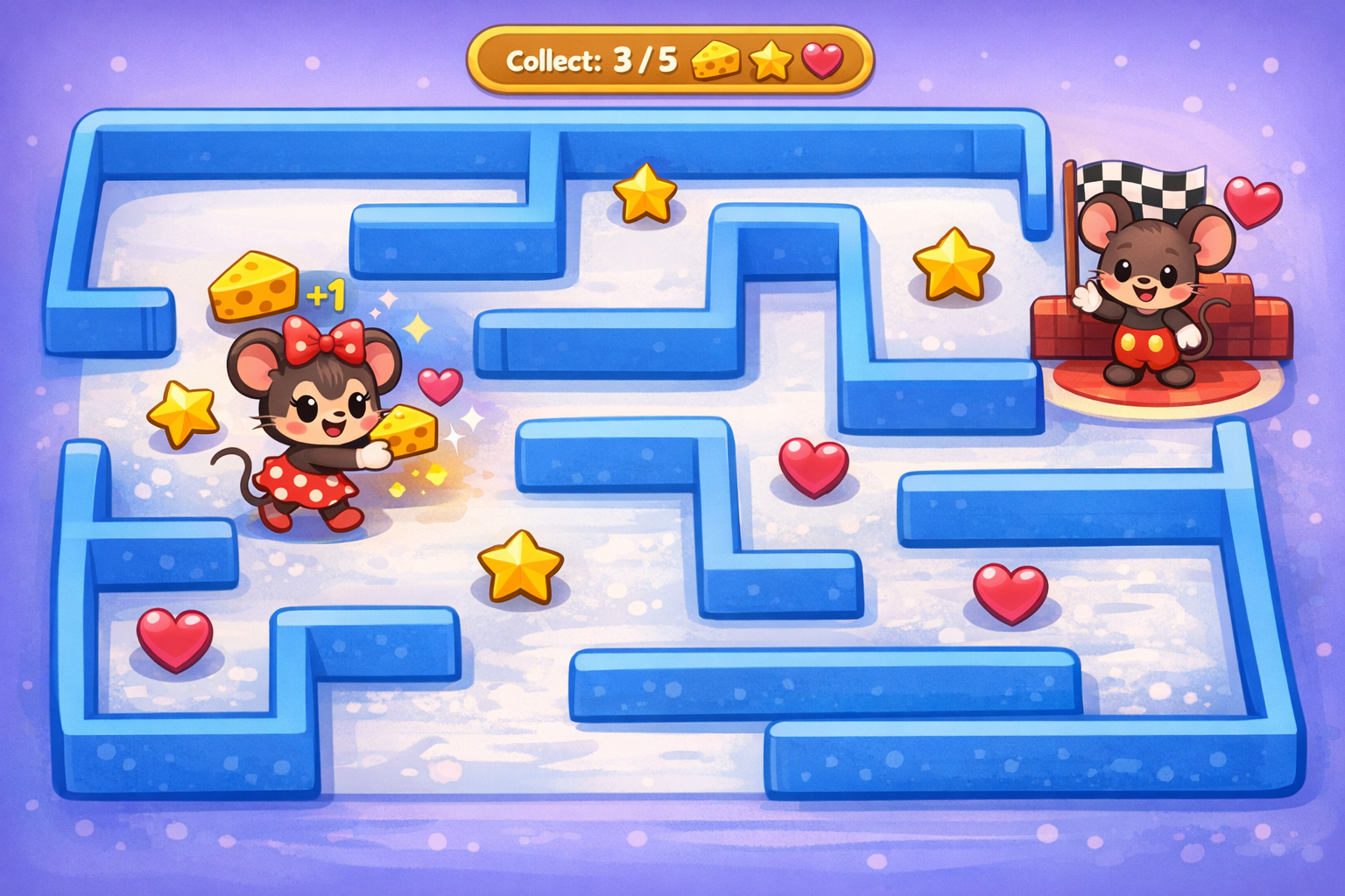
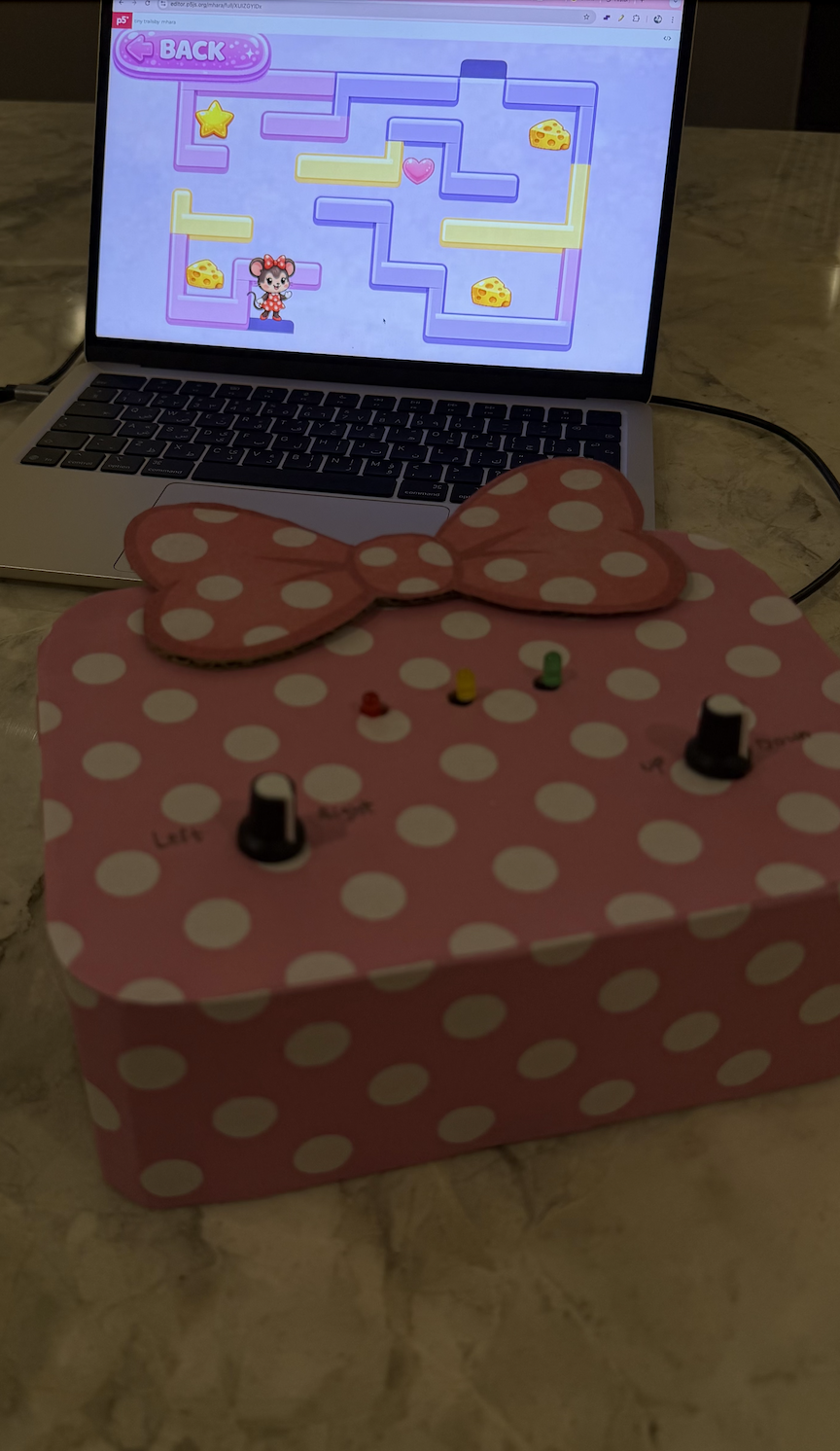
My project is an interactive maze game where the player controls Minnie Mouse using two physical potentiometers connected to an Arduino. The goal is to guide Minnie through the maze, collect all the items (cheese, stars, and hearts), and finally reach Mickey Mouse at the top of the maze. The game also uses LEDs to provide physical feedback: green for winning, yellow for collecting items, and red for hitting a wall. I chose this idea because I wanted to create something a game based on characters I love, so I picked minnie mouse and mickey.
Images and Videos of the project
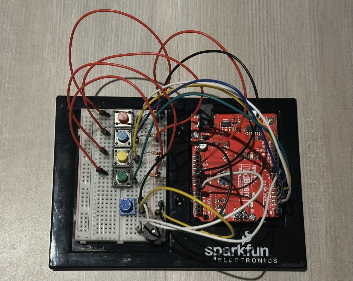
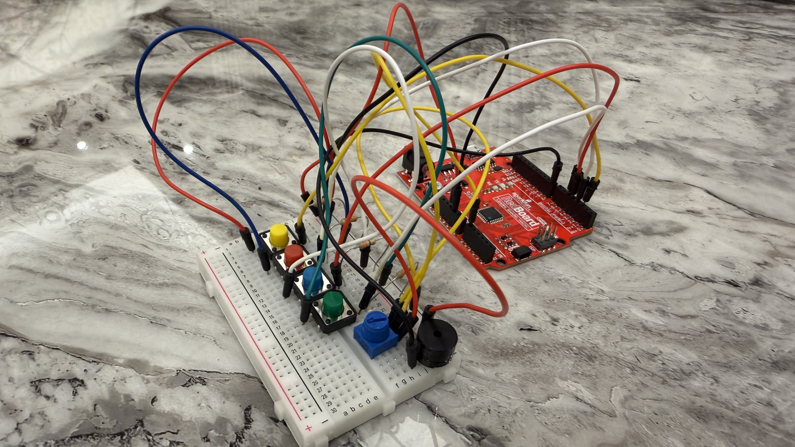
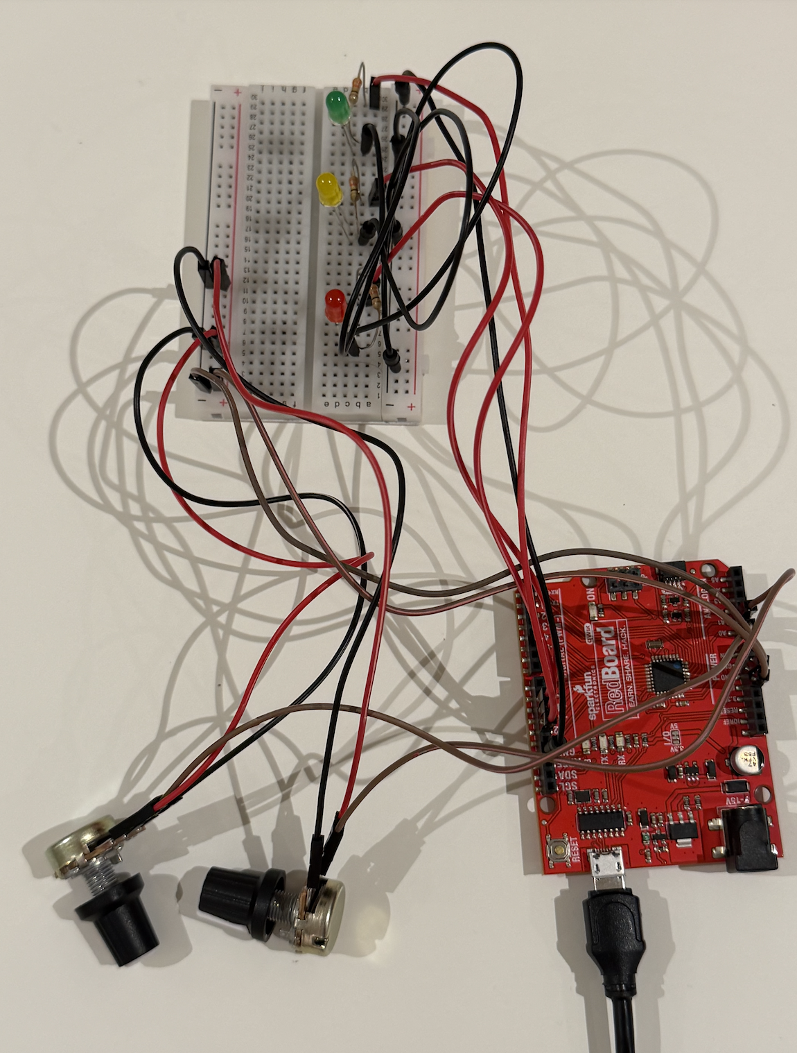
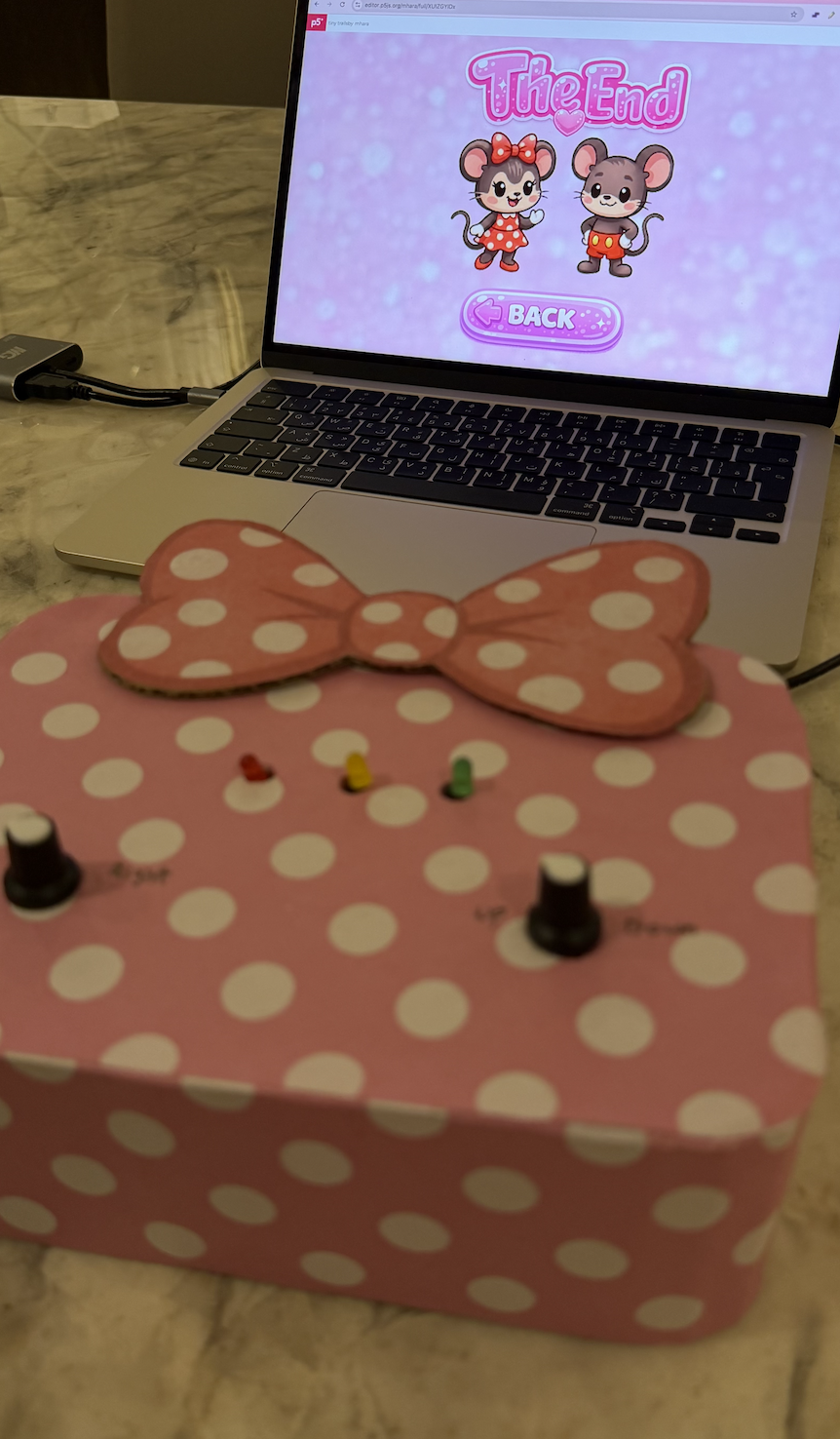
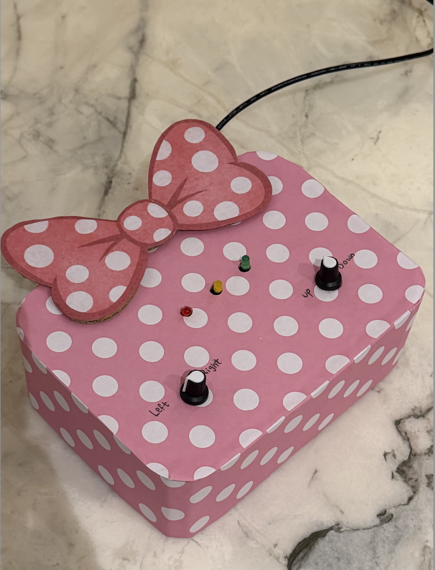
Images of my project:

Video of my project:
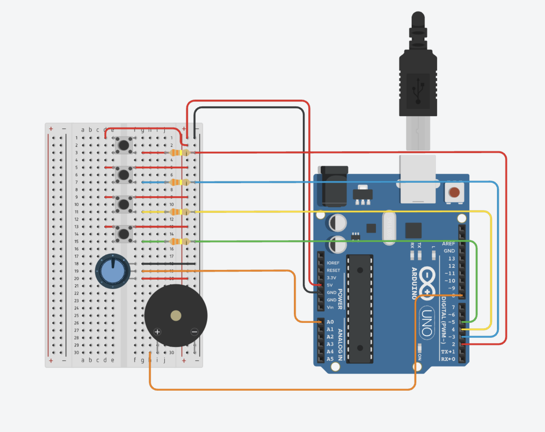
Circuit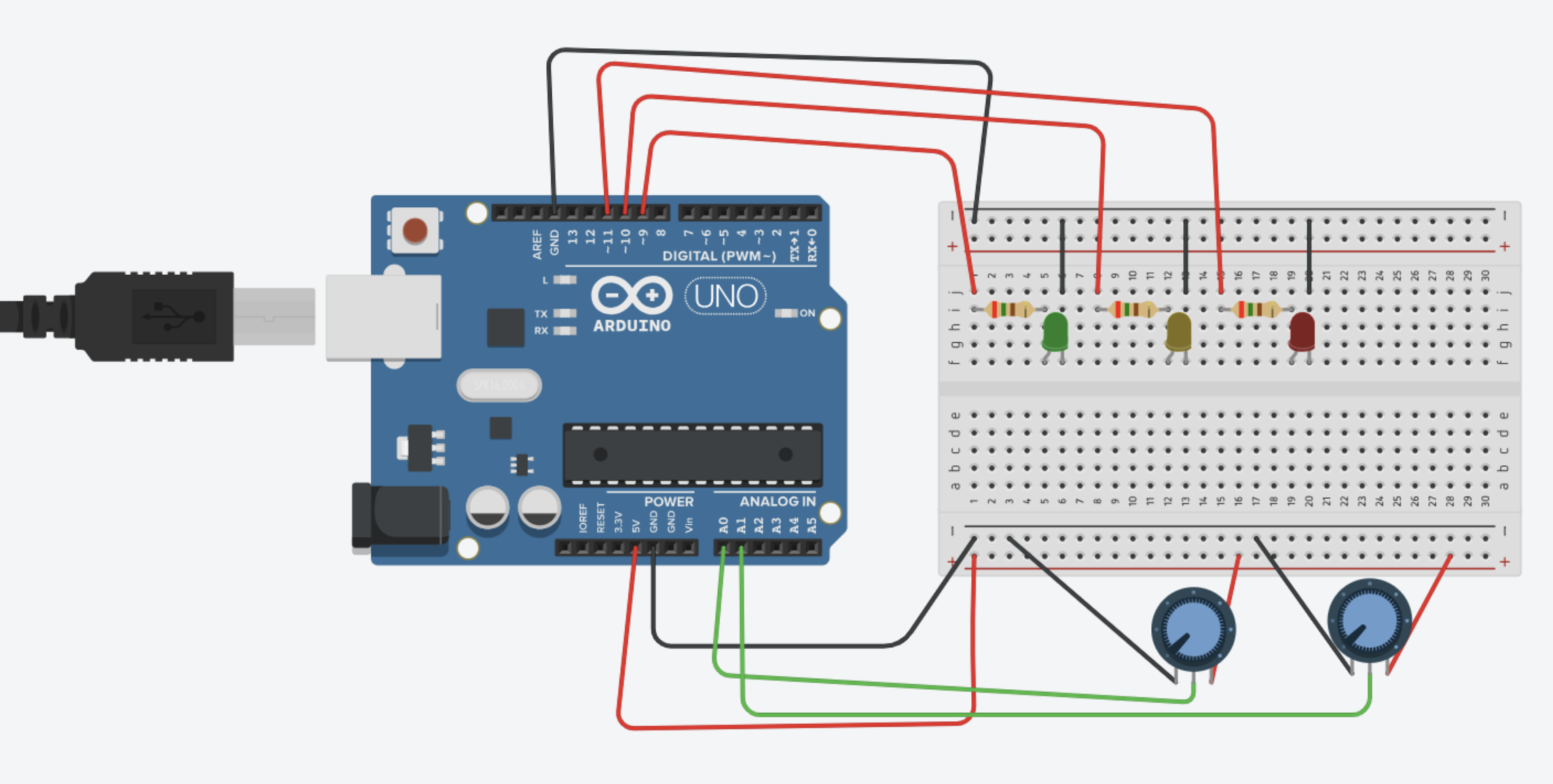
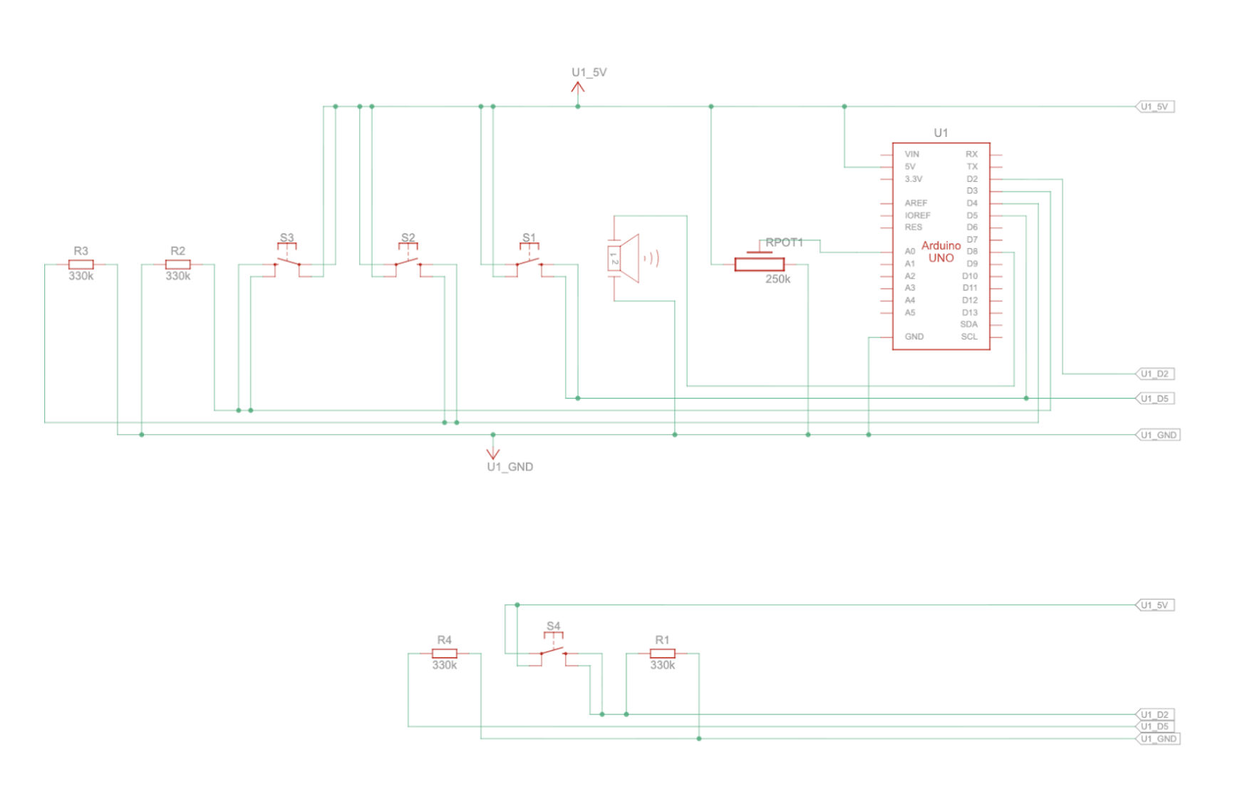
Schematic
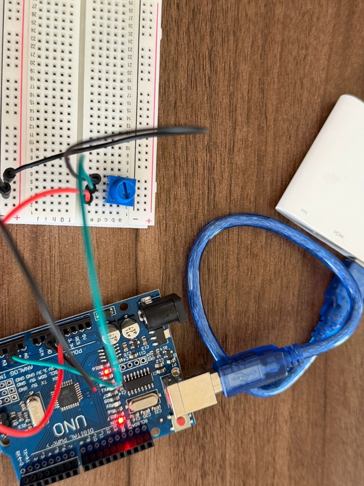
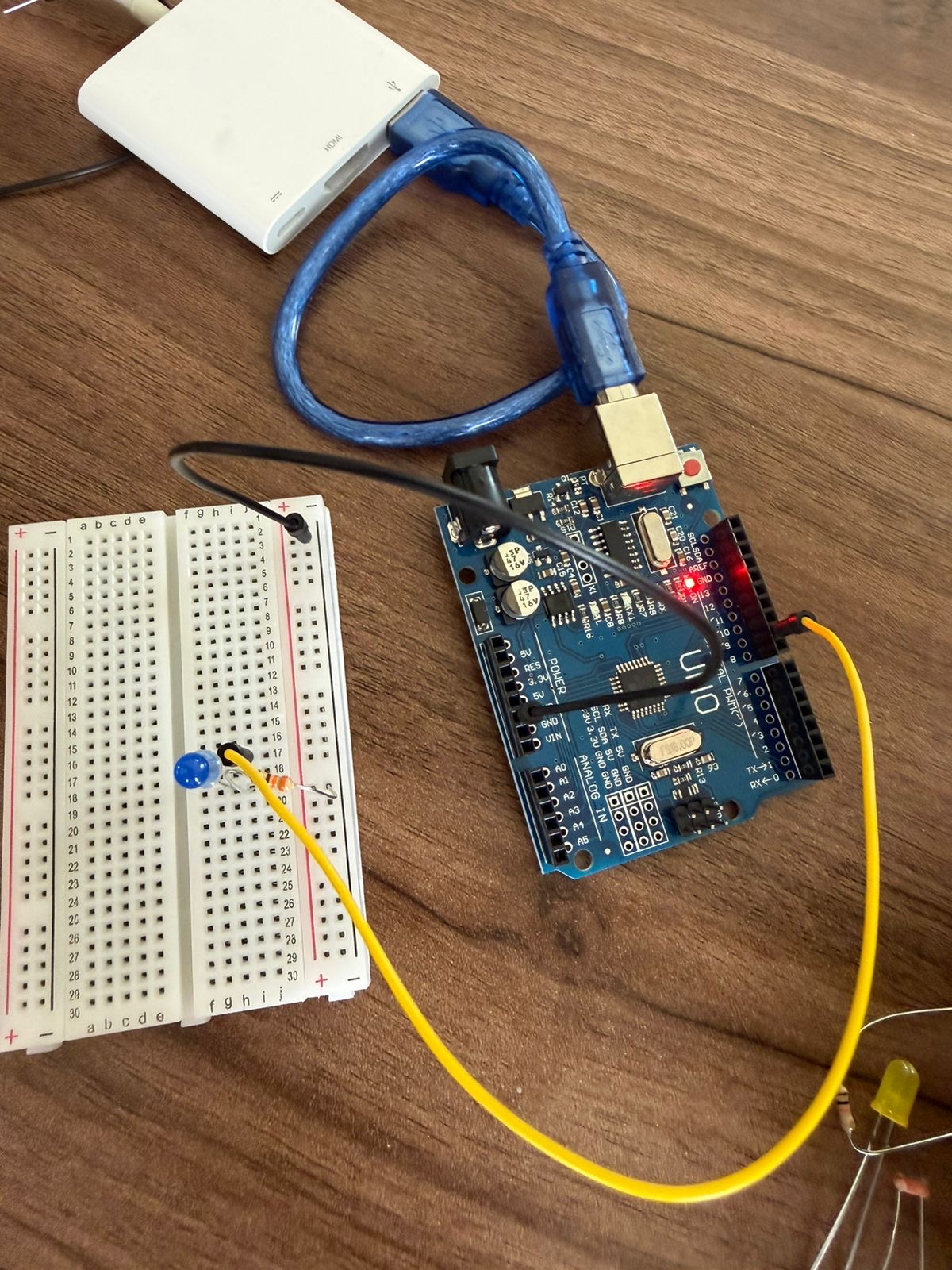
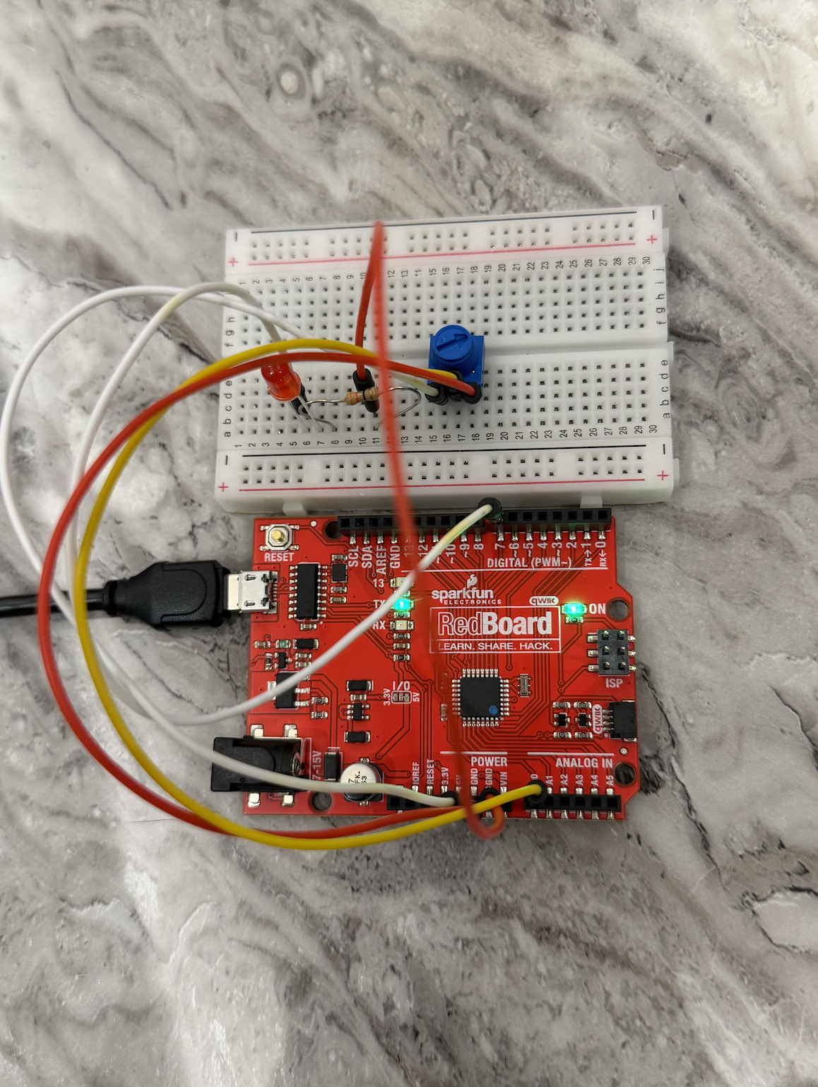
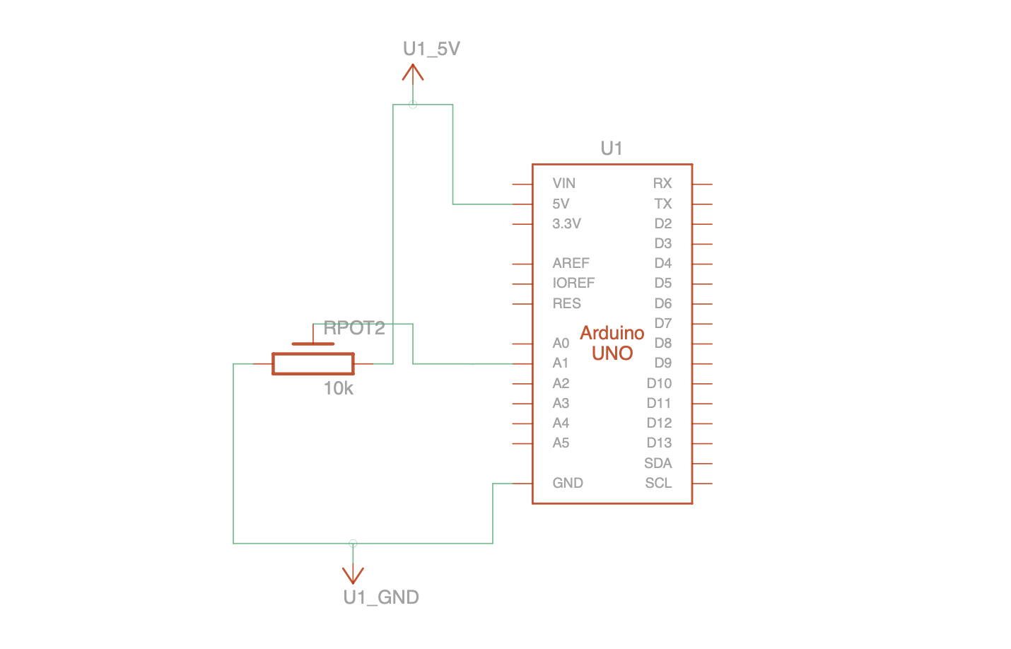
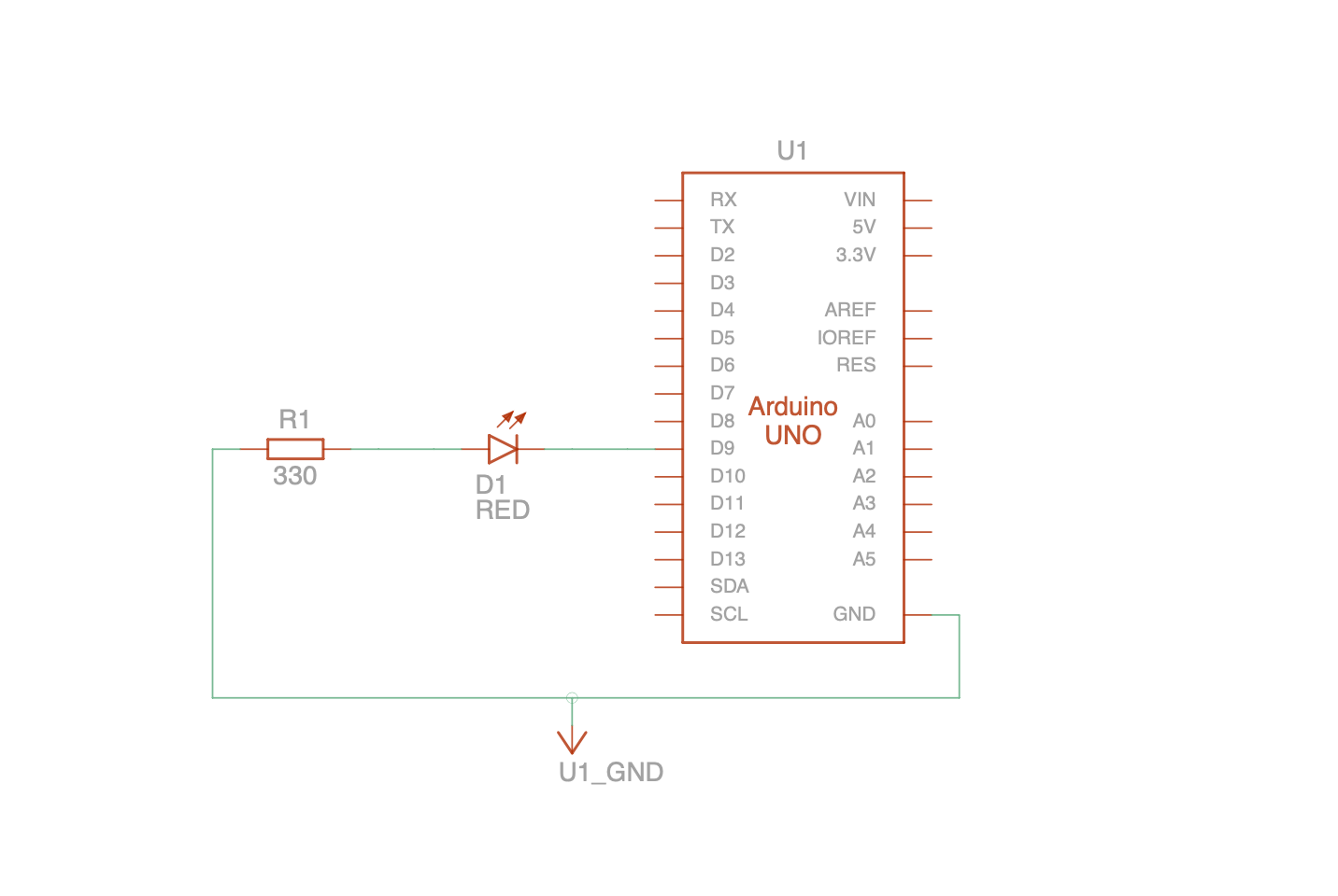
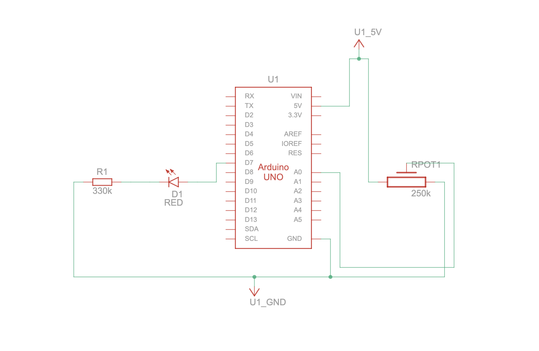
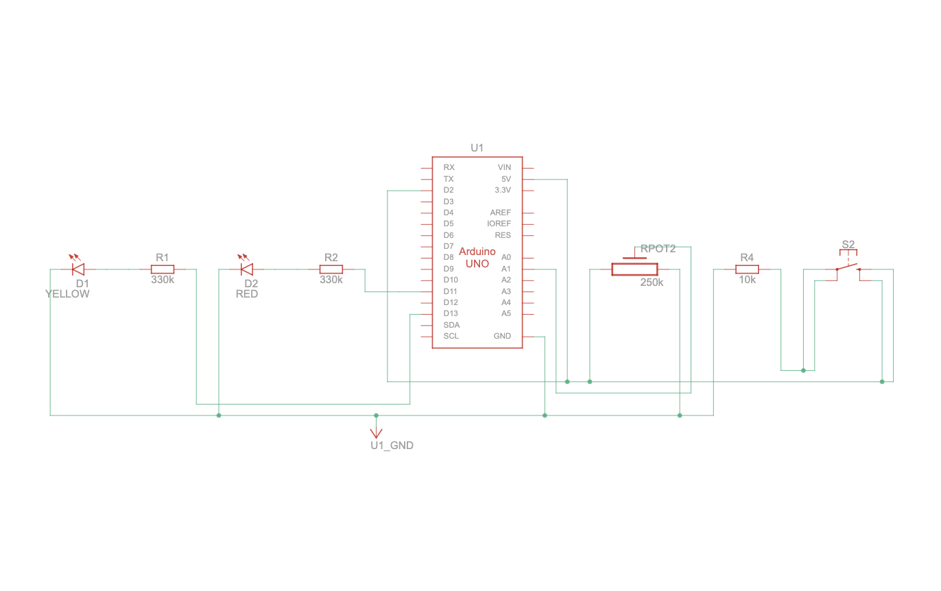
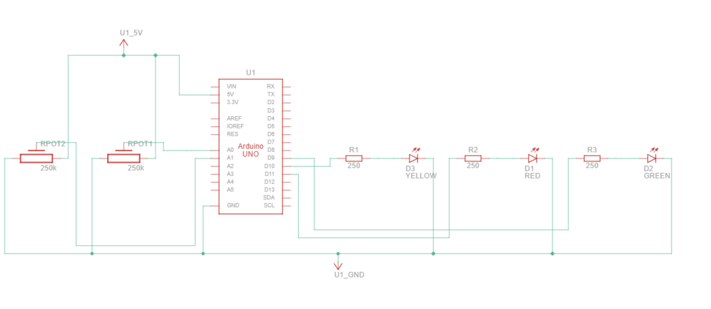 My schematic includes:
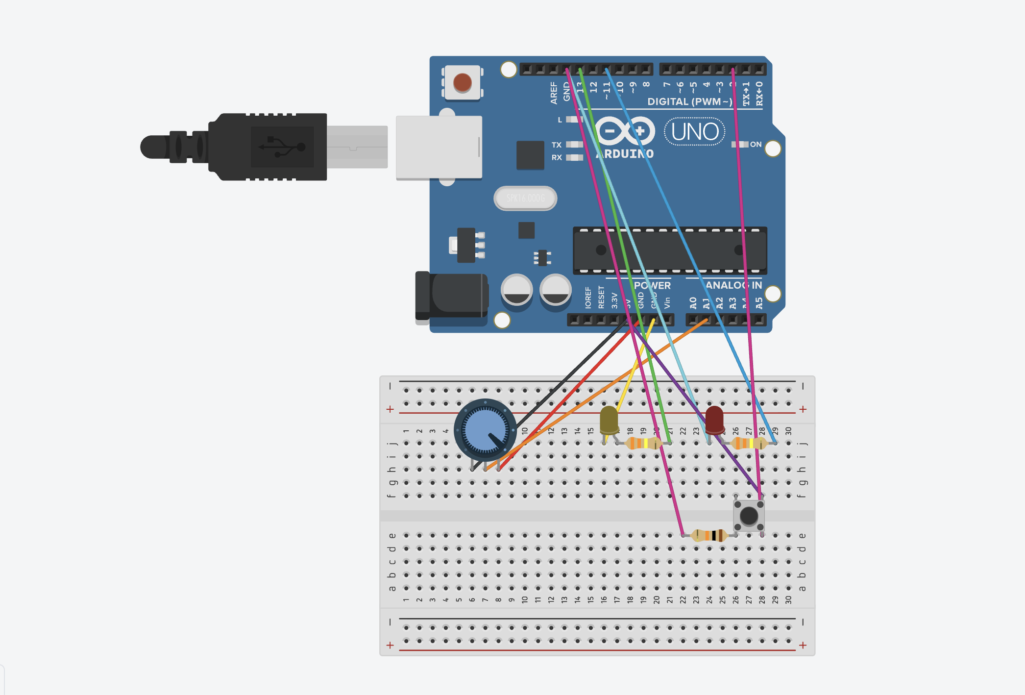
- Two potentiometers connected to A0 and A1.
- Three LEDs connected to digital pins 9, 10, and 11.
- 330 ohms resistors for each LED.
- Shared ground and 5V rails.
User Testing Video
The steps in my game
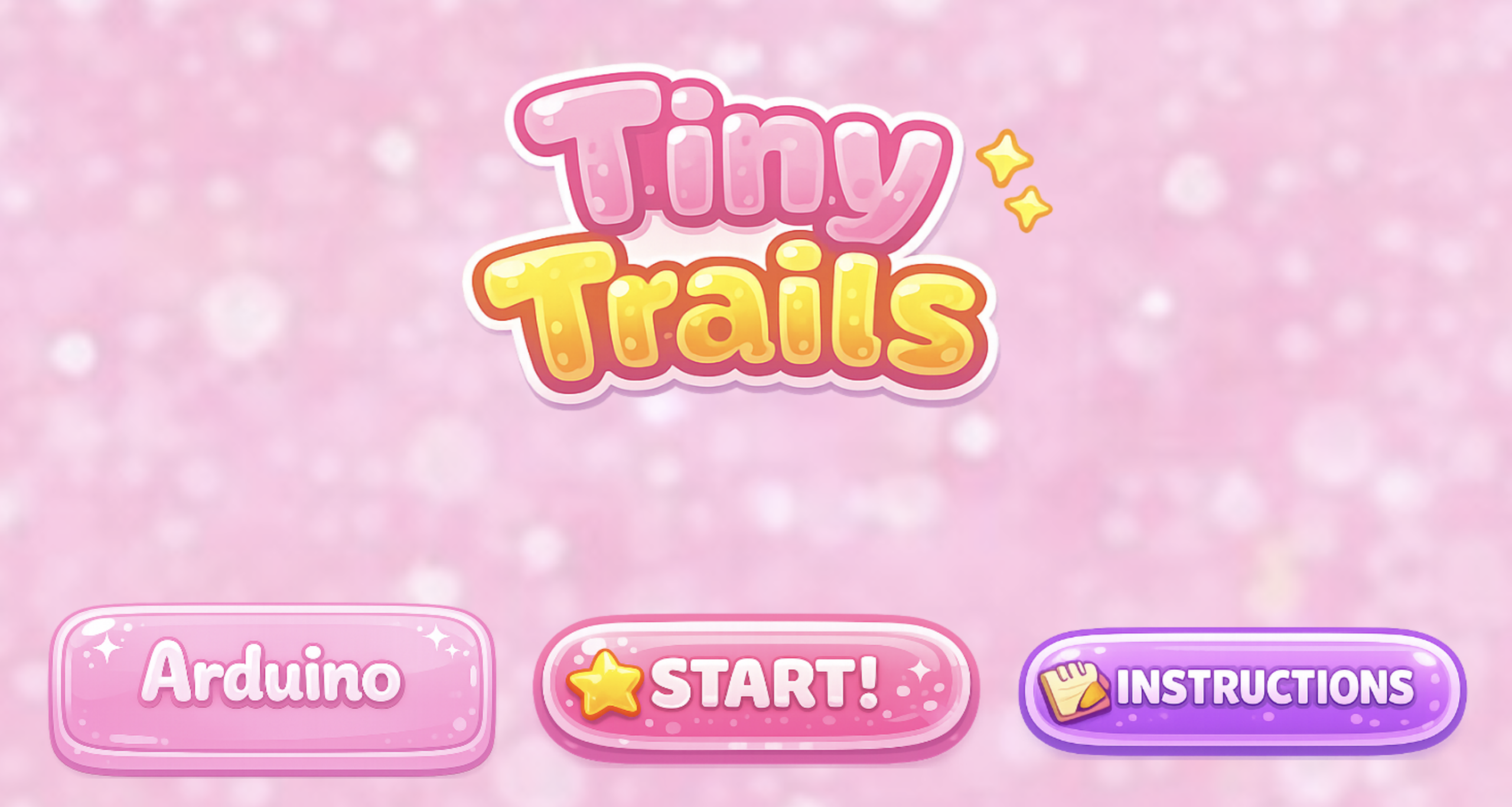
Start screen:
Instructions screen: 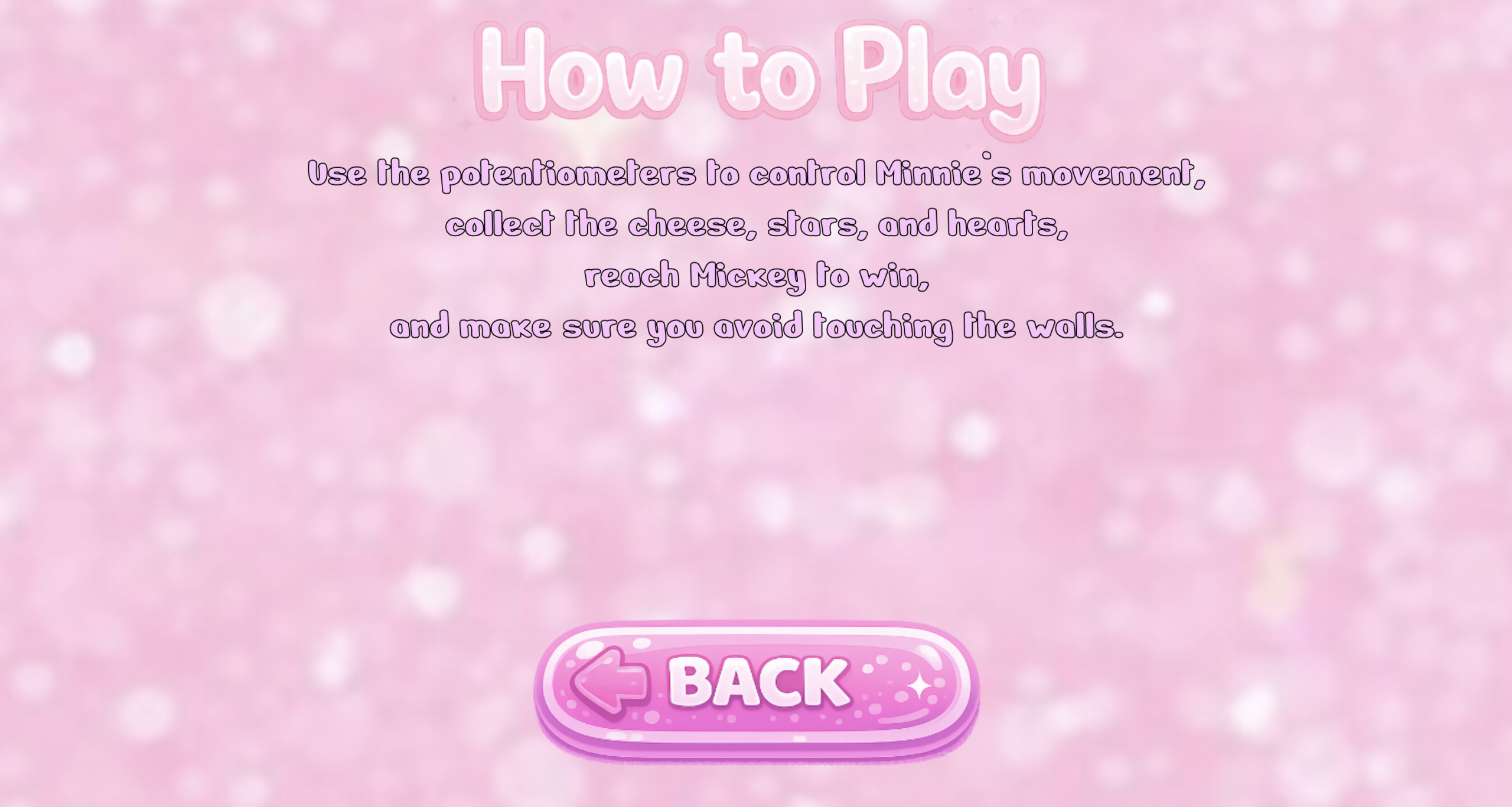
Maze game: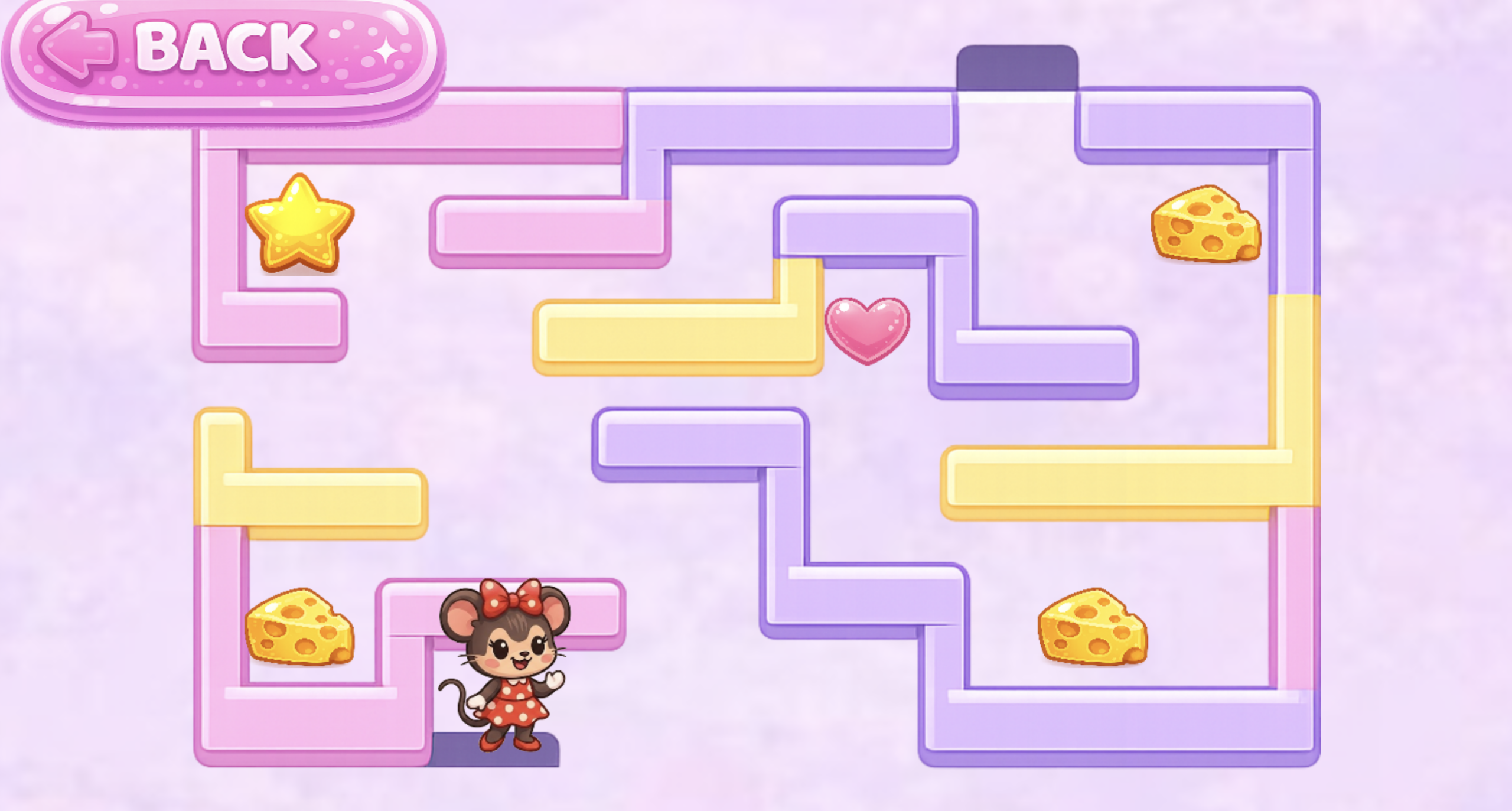
After collecting the collectibles: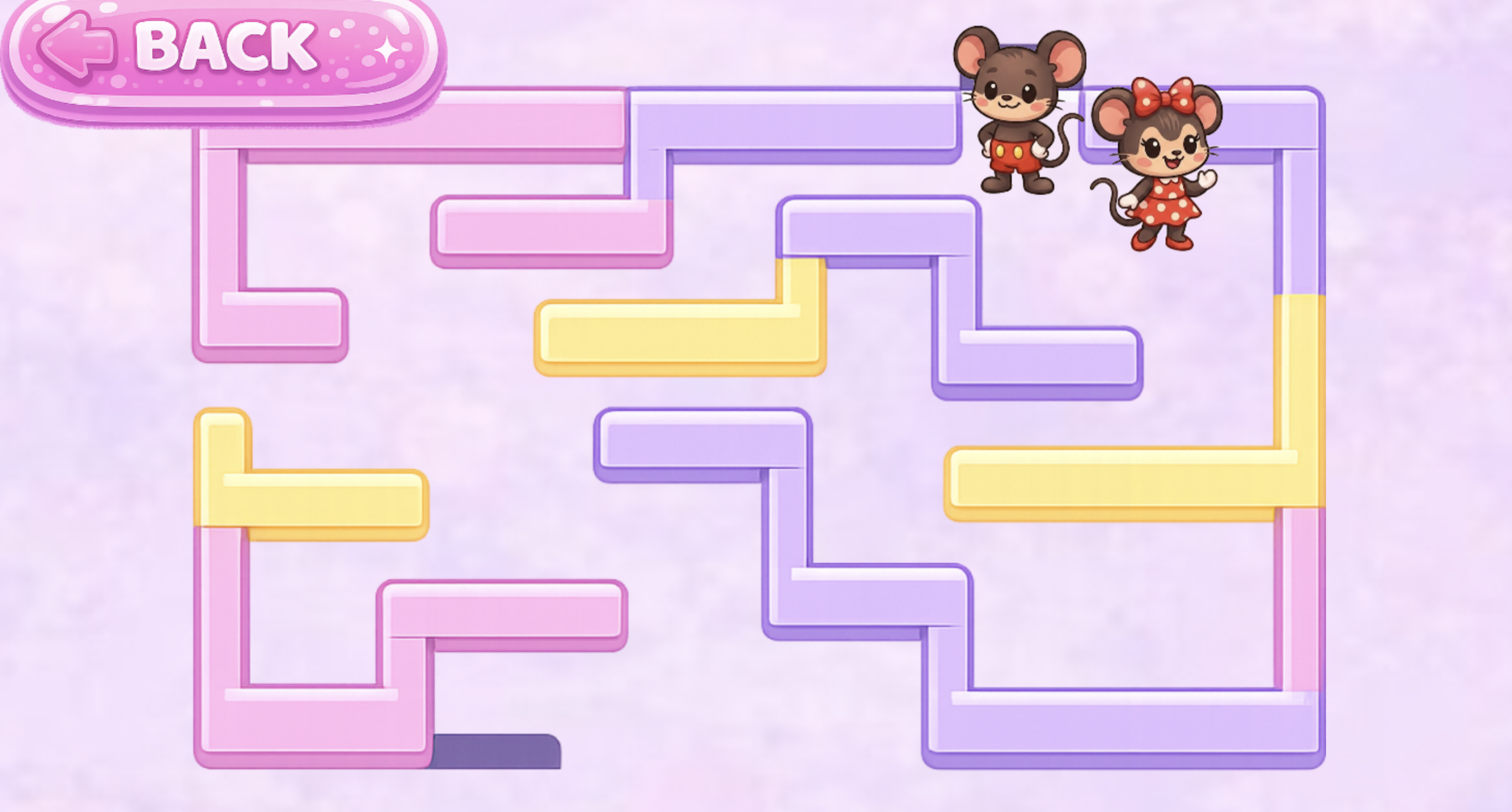
After reaching Mickey Mouse (The End):
How the Implementation Works
- Interaction Design:
The player interacts with the game using two physical knobs. One knob controls Minnie’s horizontal movement, and the other controls her vertical movement. The LEDs provide real‑time feedback such as yellow when an item is collected, red when Minnie hits a wall, and green when the player wins. Mickey only appears after all items are collected, and then the player has to go to Mickey to finish the maze to give the player a reward feeling at the end.
- Arduino Code Explanation:
The Arduino code reads the two potentiometer values and sends them to p5.js so the game can move Minnie inside the maze. At the same time, the Arduino listens for messages coming from p5.js. These messages contain the number of the LED pin that should blink when something happens in the game, such as collecting an item, hitting a wall, or winning. The Arduino then blinks the correct LED several times to give physical feedback to the player. This creates a simple but effective communication loop between the hardware and the game.
- Arduino Code Snippet:
// read the two potentiometers
int val1 = analogRead(A0);   // read first potentiometer from A0
int val2 = analogRead(A1);   // read second potentiometer from A1

// send both values to p5.js in one line
Serial.print(val1);          // send first number
Serial.print(",");           // comma so p5.js can split the values
Serial.println(val2);        // send second number and end the line
- Arduino Github link:
https://github.com/mhraalnuaimi/arduino-maze/blob/main/tiny_trails.ino
- p5.js Code Explanation:
p5.js receives the two values sent from the Arduino and uses them to update Minnie’s position inside the maze. Each value is mapped to the correct x‑ and y‑coordinates so her movement matches how far the player turns each potentiometer. After moving Minnie, the game checks for collisions with walls, collectable items, and Mickey to decide what should happen next. When an event occurs, p5.js sends a pin number back to the Arduino so the correct LED can blink, creating a simple and responsive connection between the physical hardware and the digital game.
- P5 snippet:
let data = port.readUntil("\n");  // reads one full line of data sent from the Arduino
let fromArduino = split(trim(data), ","); // splits the line into two separate values (x and y)
let xVal = int(fromArduino[0]); // converts the first value from a string into an integer for horizontal movement
let yVal = int(fromArduino[1]); // converts the second value from a string into an integer for vertical movement
let posX = map(xVal, 3, 1020, mazeLeft, mazeLeft + mazeImage.width); // maps the x value to a position inside the maze area
let posY = map(yVal, 3, 1020, mazeTop, mazeTop + mazeImage.height); // maps the y value to a position inside the maze area
minnie.move(posX, posY); // moves Minnie to the new mapped position on the screen
- P5 sketch embedded:
Used another account because the p5 I was using got throughout the semester got full.
Communication Between Arduino and p5.js:
Communication between the Arduino and p5.js happens in a simple two‑way loop. The Arduino sends two numbers from the potentiometers, and p5.js uses these numbers to move Minnie inside the maze. At the same time, p5.js sends a pin number back to the Arduino whenever something important happens in the game, like collecting one of the icons, hitting a wall, or winning. The Arduino reads this pin number and turns on the matching LED whether it was the green one for winning or yellow one for picking a collectible and red for touching any of the walls. This creates a basic but effective interaction where the hardware and the game respond to each other in real time.
Aspects I’m Proud of
I am proud of several parts of this project. The collision detection where it checks if minnie’s position overlaps with another object in the maze that includes the wall, the collectibles and mickey. I really liked that the LED sends feedback back to the player in order to show them what color is being lit up. The maze also scales well on different screen sizes, which makes the game easy to play on any device that can connect with the Arduino. During user testing, my sister understood the interaction very quickly, which showed me that the design is clear and easy to work with. Overall, I am really proud of this project because the game turned out better than expected.
Challenges Faced and How I Overcame Them
One of the first challenges I faced was with the potentiometers. The ones I ordered from Amazon were loose and unreliable, which made the game go on and off. I tried using the small Arduino potentiometers because they worked better, but they were too tiny and uncomfortable to turn. In the end, I had to order new potentiometers at the last minute, and those finally gave me smooth and stable control. Another issue was that my game wasn’t working at all at one point, Minnie was jumping all over the maze in random directions. I thought the problem was in my code, but it turned out to be a wiring mistake. The connection from the breadboard to the 5V pin was missing, so the potentiometers were sending unstable values. Fixing that single wire immediately stabilized the movement. I also ran into a major coding problem where a missing bracket caused an “unexpected end of input” error in p5. I solved this by checking each function and making sure every opening brace had a matching closing brace. Another challenge was getting the maze to scale correctly on different screen sizes. At first, the maze stretched or got cut off depending on the device. To fix this, I used Ai to calculate the two scale values: one based on the screen width and one based on the screen height. Then I chose the smaller of the two so the maze would always fit fully on the screen. This made the game look better and scaled proportionally no matter what device it was played on.
Areas for Future Improvement
There are several areas I would like to improve in the future. I want to add multiple levels of the maze, and more sound effects for reaching the different levels. I would also like to add a timer for the harder levels. Another idea is to add more physical feedback, such as additional LEDs for reaching the next level in another color other than green, yellow, or red.
Stipend Spend:
Blue Arduino Potentiometers: https://www.amazon.ae/dp/B07S69443J?ref_=pe_144460031_1285786251_i_fed_asin_title
Potentiometers: https://www.amazon.ae/dp/B0D4LKPLDT?ref_=pe_144460031_1285786251_i_fed_asin_title
Cardboard:
https://www.amazon.ae/dp/B0BWJS8W2M?ref_=pe_144460031_1285786251_i_fed_asin_title
Jumper wires: https://www.amazon.ae/dp/B0F3XDBQYX?ref_=pe_192358311_1415951701_t_fed_asin_title
Potentiometers kit (The ones I used for my arduino): https://www.amazon.ae/dp/B07ZKK6T8S?ref_=pe_151259381_1319653131_t_fed_asin_title&th=1
Citations
1. Item Pickup Sound
URL: https://opengameart.org/content/item-sfx
How I used it: I used this sound effect to play a small “pickup” noise whenever Minnie collects a cheese, star, or heart in the game.
2. Winning Sound
URL: https://freesound.org/people/Mihacappy/sounds/844146/
How I used it: I used this audio clip as the victory sound that plays when the player reaches Mickey after collecting all items.
3. Bump Sound
URL: https://pixabay.com/sound-effects/film-special-effects-retro-game-sfx-jump-bumpwav-14853/
How I used it: I used this bump sound to alert the player whenever Minnie touches a wall in the maze.
4. Majestic Rag (1914): Ben Rawls & Royal Neel (Wikimedia Commons)
URL: https://commons.wikimedia.org/wiki/File:%22Majestic_Rag%22_(1914),_by_Ben_Rawls_and_Royal_Neel.oga
How I used it: I used this music as the looping background soundtrack to give the game a fun and playful type of atmosphere.
5. Nerko One Font: Designed by Nermin Kahrimanovic (Google Fonts)
URL: https://fonts.google.com/specimen/Nerko+One?query=cute&categoryFilters=Feeling:%2FExpressive%2FPlayful&preview.script=Latn
How I used it: I used this font for the text on the instructions page to match the aesthetic of the Minnie‑themed design.
6. p5.js Image Resize Documentation
URL: https://p5js.org/reference/p5.Image/resize/
How I used it: I used this documentation to correctly resize images in the game so they scale proportionally on different screen sizes.
Ai usage:
ChatGPT helped me by explaining the math I needed to make the maze image automatically resize so it fits the screen without stretching or getting cut off. It showed me that I had to compare the maze’s size to the screen’s size and then choose the smaller scale so the whole maze stays visible. I used this explanation to write the final scaling code in my game.
Here is the snippet:
let scaleW = width / mazeImg.width;
let scaleH = height / mazeImg.height;
let scale = min(scaleW, scaleH);

mazeImg.resize(mazeImg.width * scale, mazeImg.height * scale);
This code checks how big the maze image is compared to the screen.
- scaleW is how much the image needs to shrink to fit the width.
- scaleH is how much the image needs to shrink to fit the height.
- min(scaleW, scaleH) picks the smaller number so the whole maze fits without getting cut off.
Then the image is resized using that scale so it always fits perfectly on the screen without being cut off or too stretched.
ChatGPT also helped me by generating several images that I used in the game. These include the game title “Tiny Trails,” the Start button, the Arduino Connect button, the Instructions button, the Back button, and the How to Play title on the instructions page. It also generated the maze image, the characters Minnie Mouse and Mickey Mouse, and the collectable icons: the cheese, the heart, and the star. In addition, ChatGPT created The End title and both background images used on the start page and the maze page. I also used Ai to help generate the image of the bow I printed for my physical box I made and the polka dot pattern as well.