Final Project: MindFlash

Concept

My final project was is a memory-based reaction built with Ardruino. The game displays a growing sequence of coloured LEDs and the user is supposed to repeat the exact sequence by correctly pressing the corresponding buttons. With each successful round, the game becomes more challenging by increasing the length of the sequence by one. There are three difficulty levels of this game: easy, medium and hard. The difficulty mode determines how long the sequence is displayed for. The higher the level, the shorter the display time of the sequence. The level of the game is controlled with a potentiometer.

The motivation behind MindFlash comes from my interest in memory games and sequences. I also wanted explore how a user can recall sequential information in real time. Throughout this course, there have been a lot of readings and discussions on user feedback and making designs with users at the center of the design. This idea shaped my development of the game and I placed much emphasis on the feedback and interaction of the user such as giving each button its own distinct tone, flashing the corresponding LED on every press, and using a countdown sequence before each round. Every interaction is designed to keep the player informed and engaged.

Link to Project

MINDFLASH

Demo of Project

Implementation

Interaction design

MindFlash is designed around the principle of continuous and immediate feedback at every stage of interaction. When a player presses a button, the corresponding LED lights up and a unique tone plays simultaneously, creating a sensory confirmation that their input was registered. Each of the four buttons has its own distinct pitch, so players can begin to associate sounds with colors over time. Difficulty is controlled through a potentiometer, with three levels indicated by a bank of LEDs, giving the player a clear and persistent visual indicator of their current challenge setting. The game opens with a startup test and a countdown sequence, easing the player in rather than dropping them straight into action. A correct sequence is rewarded with an ascending two-tone chime, while wrong inputs trigger a distinctly different falling sound, making success and failure immediately distinguishable without the player needing to look away from the LEDs. The game over state further reinforces failure through a flashing all-LED pattern.
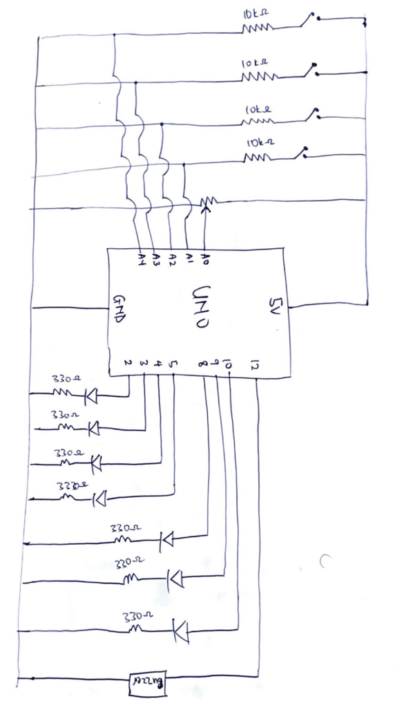
Sketch

Ardruino code

/*
  MINDFLASH GAME
  
  OUTPUTS
  2  - Green LED
  3  - Yellow LED
  4  - Red LED
  5  - Blue LED
  8  - Level LED 1
  9  - Level LED 2
  10 - Level LED 3
  12 - Piezo buzzer
  INPUTS  
  A0  - Potentiometer
  A1  - Button (S2)
  A2  - Button (S4)
  A3  - Button (S1)
  A4  - Button (S3)
*/

// PIN DEFINITIONS
const int LED_PINS[]   = {2, 3, 4, 5};       
const int BTN_PINS[]   = {A1, A2, A3, A4};   
const int LVL_LEDS[]   = {8, 9, 10};
const int BUZZ_PIN     = 12;
const int POT_PIN      = A0;
const int NUM_COLORS   = 4;
const int MAX_SEQ      = 20;

// BUTTON TONES 
const int BTN_TONES[]  = {415, 310, 250, 210};

// GAME STATE
int sequence[MAX_SEQ];
int seqLen   = 1;
int flashDur = 500;

// SOUNDS 
void beep(int freq, int dur) {
  tone(BUZZ_PIN, freq);
  delay(dur);
  noTone(BUZZ_PIN);
}
void correctSound() {
  beep(1000, 100); beep(1300, 200);
}
void wrongSound() {
  beep(330, 250);
  beep(220, 250);
  beep(147, 550);
}

// BUTTON FEEDBACK (light + sound together)
void buttonFeedback(int btnIdx) {
  tone(BUZZ_PIN, BTN_TONES[btnIdx]);   // start tone
  digitalWrite(LED_PINS[btnIdx], HIGH);
  delay(150);
  noTone(BUZZ_PIN);                    // stop tone
  digitalWrite(LED_PINS[btnIdx], LOW);
  delay(50);
}

// LIGHTS
void allLedsOff() {
  for (int i = 0; i < NUM_COLORS; i++) digitalWrite(LED_PINS[i], LOW);
}
void allLedsOn() {
  for (int i = 0; i < NUM_COLORS; i++) digitalWrite(LED_PINS[i], HIGH);
}
void flashLed(int idx, int dur) {
  tone(BUZZ_PIN, BTN_TONES[idx]);      // play tone during sequence flash too
  digitalWrite(LED_PINS[idx], HIGH);
  delay(dur);
  noTone(BUZZ_PIN);
  digitalWrite(LED_PINS[idx], LOW);
  delay(200);  
}

// READ DIFFICULTY 
void readMode() {
  int pm = analogRead(POT_PIN);
  if (pm >= 700) {
    digitalWrite(8,HIGH); digitalWrite(9,LOW);  digitalWrite(10,LOW);
    flashDur = 700;
  } else if (pm >= 350) {
    digitalWrite(8,HIGH); digitalWrite(9,HIGH); digitalWrite(10,LOW);
    flashDur = 500;
  } else {
    digitalWrite(8,HIGH); digitalWrite(9,HIGH); digitalWrite(10,HIGH);
    flashDur = 300;
  }
}

// SHOW SEQUENCE 
void showSequence() {
  delay(1000);
  for (int i = 0; i < seqLen; i++) flashLed(sequence[i], flashDur);
  delay(300);
}

// WAIT FOR ONE BUTTON PRESS
int waitForButton() {
  while (true) {
    for (int b = 0; b < NUM_COLORS; b++) {
      if (digitalRead(BTN_PINS[b]) == HIGH) {
        delay(40);                                
        while (digitalRead(BTN_PINS[b]) == HIGH); 
        return b;
      }
    }
  }
}

// GET USER INPUTS & VERIFY 
bool getUserInputs() {
  for (int i = 0; i < seqLen; i++) {
    int btn = waitForButton();
    buttonFeedback(btn);
    if (btn != sequence[i]) return false;
  }
  return true;
}

// COUNTDOWN 
void countdown() {
  for (int i = 3; i > 0; i--) {
    allLedsOn();
    beep(800 + (3 - i) * 150, 150);
    delay(700);
    allLedsOff();
    delay(200);
  }
  // GO!
  allLedsOn(); beep(1400, 200); allLedsOff();
  delay(400);
}

// GAME OVER 
void showGameOver() {
  wrongSound();
  for (int b = 0; b < 4; b++) {
    allLedsOn();  delay(300);
    allLedsOff(); delay(300);
  }
  delay(800);
}

// SETUP 
void setup() {
  Serial.begin(9600);
  for (int i = 0; i < NUM_COLORS; i++) {
    pinMode(LED_PINS[i], OUTPUT);
    pinMode(BTN_PINS[i], INPUT);   
  }
  for (int i = 0; i < 3; i++) pinMode(LVL_LEDS[i], OUTPUT);
  pinMode(BUZZ_PIN, OUTPUT);
  // startup test
  allLedsOn();
  digitalWrite(8,HIGH); digitalWrite(9,HIGH); digitalWrite(10,HIGH);
  beep(1000, 400);
  delay(600);
  allLedsOff();
  digitalWrite(8,LOW); digitalWrite(9,LOW); digitalWrite(10,LOW);
  randomSeed(analogRead(A5)); 
}

// MAIN LOOP 
void loop() {
  readMode();
  // wait for any button press to start
  bool started = false;
  for (int b = 0; b < NUM_COLORS; b++)
    if (digitalRead(BTN_PINS[b]) == HIGH) { started = true; break; }
  if (!started) return;
  // debounce the start press
  delay(50);
  while (digitalRead(BTN_PINS[0]) == HIGH ||
         digitalRead(BTN_PINS[1]) == HIGH ||
         digitalRead(BTN_PINS[2]) == HIGH ||
         digitalRead(BTN_PINS[3]) == HIGH);
  allLedsOff();
  seqLen = 1;
  readMode();
  countdown();
  while (seqLen <= MAX_SEQ) {
    sequence[seqLen - 1] = random(0, NUM_COLORS);
    Serial.print("Round "); Serial.println(seqLen);
    showSequence();
    if (getUserInputs()) {
      correctSound();
      seqLen++;
      delay(500);
    } else {
      showGameOver();
      seqLen = 1;
      break;
    }
  }
  allLedsOff();
  delay(500);
}


How It’s Made

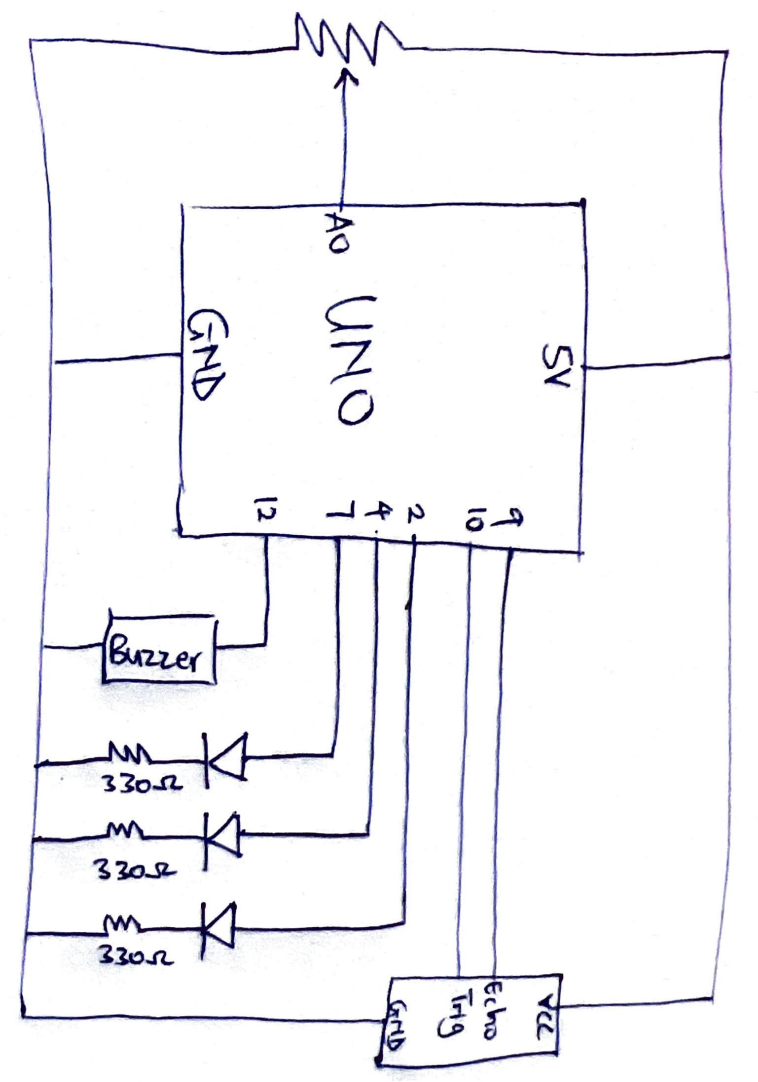
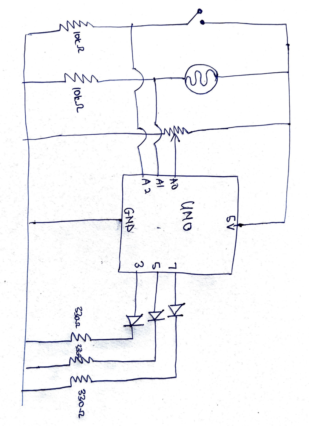
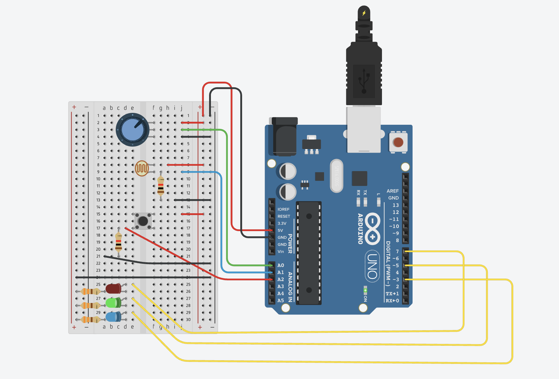
For this project, the inputs are push switches and a potentiometer. A potentiometer was connected to the 5V power source, an analog read pin and ground. The analog read pin reads the value of the potentiometer to control the level of the game. 4 push switches were connected in parallel to the 5V power source, an analog read pin and a pull down resistor of 10kΩ resistor to ground. The analog pins read the digital inputs of the push switches and that is used as the logic for matching the sequences.

The outputs of the project are a buzzer and sets of LEDs. The LEDs were connected to digital pins, a 330Ω resistor and ground. There are two sets of LEDs for this project. Set A is a set of 3 red LEDs and these LEDs indicate to the user the level of the game. The code reads the value of the potentiometer and maps it to one of the three level and this is reflected by the red LEDs. Easy mode lights up one LED, medium lights up two LEDs and hard lights up three LEDs. Set B is a set of 4 LEDs: red, yellow, blue, green. A random sequence is generate out of these colors and the user is supposed to match this using the push switches. The final output is a buzzer which is connected to a digital pin and ground. The buzzer makes sound for a countdown to start the game, makes a success sound, wrong sound and sounds specific to each color.

The pressing the push button lights up the corresponding LED bulb and makes a sound specific to that color. Chat GPT was used to generate the frequencies of sounds for the countdown, success sound, wrong and game over sound, and the sounds corresponding to each color.

Part of the project I’m proud of

The part of this project I’m particularly proud of is the code behind this project. The most difficult part of the project was writing my idea of the project into a working code and figuring it out made me very proud. The highlight of the code were the functions I made for the game.

void readMode() {
  int pm = analogRead(POT_PIN);
  if (pm >= 700) {
    digitalWrite(8,HIGH); digitalWrite(9,LOW);  digitalWrite(10,LOW);
    flashDur = 700;
  } else if (pm >= 350) {
    digitalWrite(8,HIGH); digitalWrite(9,HIGH); digitalWrite(10,LOW);
    flashDur = 500;
  } else {
    digitalWrite(8,HIGH); digitalWrite(9,HIGH); digitalWrite(10,HIGH);
    flashDur = 300;
  }
}

This is the function that controls the level of the game. The reason this is the highlight of the whole project for me is that writing this code was a breakthrough moment for me. Once I figured this part out, everything else seemed to follow and I was able to implement my ideas.
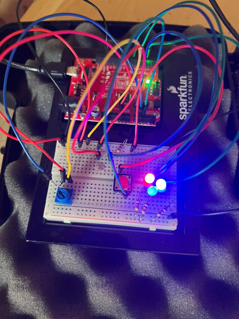
Reflection

Making this project was actually very fun. A new layer of complexity was added when implementing my ideas because as aside the code, I also had to figure out the connections of the circuits. I found myself placing LEDs at almost every point to check if the connections I had made were right in the testing phase. The LEDs were my debuggers for this project. I also played around a lot with the delay function in the project to ensure a smooth user interaction

The user testing opened me up to things I missed during my testing of the program and changed how I thought about the whole project. It made me add more feedback for the user especially being in a virtual space where a user could not physically feel a button, adding these feedbacks improved the overall project and I hope these feedbacks will be enough for a user in a virtual space.

Future improvements for this project is introducing a scoring system which is based on the time the user presses the buttons. This can expand the project from just testing memory to testing memory and reaction. The scoring system can also be used to create a leaderboard and it will be a fun game to play among friends.

Week 13 – User Testing

User Interaction with project

For this exercise, I had my friend test my project without explaining the concept of project to him and recorded his reaction, asked his thoughts after the testing, explained the concept to him and he made some suggestions on how to improve the project.

The goal of the game was to match the sequence of the LED lights by pressing push switches. He struggled to find which LED corresponds to which switch because all the switches were of the same color. TinkerCAD does not give the option to change the color of the switch. I wanted to use colored switches to indicate which switch controlled which LED by matching the color of the LEDs but that was not successful. One he figured out which switch corresponds to the color of LED though he went on playing with the game.

Another thing my friend struggled with when playing my game was the feedback from the switch buttons. Since the game was virtual and done in TinkerCAD, he could not tell if he had successfully pressed the switch or not. This led to him pressing the buttons more times than he should have, giving him wrong outputs. This was a problem that run throughout the testing phase.

There was a potentiometer controlling the speed and level of the game but the user did not interact with it at all. It look isolated from the game system and his mind did not go to it at all. He was more focused on matching the pattern of the LEDs. He only interacted with it when I pointed it out after the testing.

Overall, he liked the idea of the game and the system behind it but struggled with the colors and the virtual interface of the project. He also suggest I used sound and light feedbacks when the buttons are pressed to alert the user.

I am glad the functionality of my project works, now for the final project, I need to find a way to direct the users attention to the levels possible and provide feedback of the the buttons with sound and light. For the colors of the switch, I am not sure of what to do of it next, but I need to find a way to let the user know the specific LED controlled by the switch if I cannot use colors of the LED.

User Interaction

Week 12 – Final project proposal

For my final project, I propose building Flash Match, an phyiscal Arduino-based reflex and memory game that combines elements of Simon Says with a reaction time challenge. The game uses four coloured LEDs (red, yellow, green and blue) and four corresponding push buttons as the core interface. Each round begins with a countdown, after which the Arduino displays a sequence of flashing LEDs that grows by one light every round. The player must press the matching button for each LED in the correct order and as quickly as possible. The reaction speed directly determines the points awarded per press, with faster responses earning higher scores. A wrong button press ends the game immediately, at which point the player’s total score is shown on a LCD display . Additional components include a buzzer for audio feedback.

The most challenging part about the game is figuring out how to use the LCD display in ardruino and making sure the game feedback is quick enough to give the user a good experience.

Week 12 – Reading response

This reading relates to a class I am currently taking called disability in musical contexts where we talk about disabilities studies and this “medical model” where disabilities are treated as problems to be solved negatively affect individuals. They will most likely try to hide their disabilities. They will prefer a design of accommodation that speaks about their disabilites the least. But in this text, we realise that a good design can acutally make someone confident about that  impairment they have and I makes me wonder how a good design for something meant to disabled people can seep into mainstream media.

Take for instance the Apple AirPods. Apple has focused so much on their design and the product that they can be used as hearing aids for people with mild or little hearing loss, and in this case, you cannot distinguish who is using the airpods as support or just for entertainment. This is an example of good design that can boost the confidence of a person with hearing loss and it combines functionality and style.

Week 11 – Reading response

This article was really interesting when talking about about physical implements and how they affect user. This goes back to the recurring theme of designing interactive system where the user should be the center of the design and user feedback. The idea of pictures under glass in my opinion creates a pseudo-realistic feeling where everything is meant to imitate the actual objects not not give the user the actual feeling and new design principles are becoming more and more virtual which makes I question how much humans will be involved with tools or implements in the coming period and we may actually lose touch with what we deem as reality now. The reading itself was very self-explanatory so I do not have much to say but it was just a simple reminder to keep in touch with physical things when designing interactive systems.

Week 11 – Production Assignment (Air Piano)

Concept

The “Air Piano” is a musical instrument controlled using the distance from a sensor. I have always been fascinated by the distance sensors, using reflection of sound waves to calculate the distance of an object. I used the the HC-S04 sensor to detect the distance in this work as input for the instrument. I was inspired by the tone knob in electrical guitars which was discussed in class so I integrated it into my work. A potentiometer serves as my tone knob and its input is used to switch among 3 sound modes: Piano mode, Sci-Fi mode and Bass Mode. There are also different colored LEDS to show the user which mode is on. Red – Piano, Green – SciFi and Blue – Bass mode. The mode determines the scale of frequency produced by the buzzer. The coding behind this project was to map the distance of an object from the sensor to a value from 0 to 7 (8 values) and these values each correspond to a specific note.

Sketch

Image

Code

// A0 - Potentiometer
// 2 - Blue
// 4 - Green
// 7 - Red
// 12 - Buzzer 

const int trigPin = 10;
const int echoPin = 9;

// Mode 1 - Piano Scale
int mode1[8] = {262, 294, 330, 349, 392, 440, 494, 523};

// Mode 2 - Sci-Fi
int mode2[8] = {600, 750, 900, 1100, 1400, 1800, 2300, 3000};

// Mode 3 - Higher Bass / Bright Low Mode
int mode3[8] = {350, 420, 500, 600, 720, 850, 1000, 1200};

float duration;
int distance;

void setup() {
  pinMode(trigPin, OUTPUT);
  pinMode(echoPin, INPUT);
  pinMode(2, OUTPUT);
  pinMode(4, OUTPUT);
  pinMode(7, OUTPUT);
  pinMode(12, OUTPUT);

  Serial.begin(9600);
  digitalWrite(2, HIGH);
  digitalWrite(4, HIGH);
  digitalWrite(7, HIGH);
  delay(1000);

  digitalWrite(2, LOW);
  digitalWrite(4, LOW);
  digitalWrite(7, LOW);
}

void loop() {
  digitalWrite(trigPin, LOW);
  delayMicroseconds(2);
  digitalWrite(trigPin, HIGH);
  delayMicroseconds(10);
  digitalWrite(trigPin, LOW);
  int mode;

  int pm = analogRead(A0);

  duration = pulseIn(echoPin, HIGH);
  distance = (duration*0.0343)/2;

  Serial.print("Distance: ");
  Serial.println(distance);
  delay(100);

  if (pm >= 700) {
    mode = 0;
    digitalWrite(7, HIGH);
    digitalWrite(2, LOW);
    digitalWrite(4, LOW);
  } else if (pm >= 350) {
    mode = 1;
    digitalWrite(4, HIGH);
    digitalWrite(7, LOW);
    digitalWrite(2, LOW);
  } else {
    mode = 2;
    digitalWrite(2, HIGH);
    digitalWrite(4, LOW);
    digitalWrite(7, LOW);
  }

  if (distance >= 0 && distance <= 40) {

    int noteIndex = map(distance, 0, 40, 0, 7);
    int freq;

    if (mode == 0) freq = mode1[noteIndex];
    if (mode == 1) freq = mode2[noteIndex];
    if (mode == 2) freq = mode3[noteIndex];

    tone(12, freq);
  }
  else {
    noTone(12);
  }

  //delay(50);
}


How it was made

This work was made by first drawing the sketch of the circuit. The inputs are the resistance value of the potentiometer and the distance from the distance sensor. I had to watch a video and use the ardruino website to figure out how to configure the distance sensor. The output of the circuit are 3 LEDs and a buzzer. The LEDs where connected to digital pins, a resistor and ground. The buzzer was connected to a digital pin and ground. In the coding of the instrument, I used ChatGPT to generate an array of frequencies corresponding to the modes. I connected all the wires and components according to the sketch.

Reflection

Being someone with no knowledge in music, I thought this work will be very difficult for me but after I figured out the input and output of the program, it went quite smoothly. To improve the project, a more sensitive distance sensor can be used to improve the readings of the sensor and more modes with different frequencies can be added to create more musical effects.

Week 10 – Reading response

Making Interactive Art Text challenged my view about art. I used to see art as an aggregations of different elements and ideas that allow an artist to tell a story. I assumed interactive art was the same way were although the user takes part in the art, they will be an actor in the play of the artist. This texts challenges my notion and tells me that the artist must only set the stage and allow the user to explore. I like this idea but my questions comes to, what are the bounds of exploration and if there are bounds of exploration does the artist still not control the narrative. Take for instance open world games. There are many things you can do in the open world but not all things are allowed. There are specific characters one can interact with and are aligned towards a central theme of the story line of the game. As I explore interactive media more, I look forward to finding the line between user exploration and artist control in interactive arts

In the Physical computing greatest hits text, we see various examples of physical computing art. What specifically catches my eye is the direct bodily feedback machines such as the gloves and the cursor devices. In my opinion they give user more sense of control and more immersed into the art than objects that just measure inputs from the environment such as the field of grass. This also raises the question about the measure of interactiveness. Can one say one art is more interactive than another passed on the feedback of the control parameters of the art and can this affect the judgement and interpretation of the work.

Week 10 – Production Assignment

Concept

The concept of this project is to create an system can make light of any colour using rgb values. In the last class we learnt about analogue and digital input and output. Using this concept, I created a circuit that uses analogue input to control the brightness of a red, green and blue led to obtain a specific color, just as we could pick specific colors when coding in p5js.

A photo-resistor, potentiometer and push switch are used to control the rgb values of the LEDs and the lights were physically merged together so as to give the idea they were producing one light of a specified color.

Sketch

Code

// A0 = Potentiometer input
// A1 = Photoresistor input
// A2 = Push switch input
// 3 = Blue LED to resistor to GND
// 5 = Green LED to resistor to GND
// 7 = Red LED to resistor to GND

void setup() {
  pinMode(3, OUTPUT);
  pinMode(5, OUTPUT);
  pinMode(7, OUTPUT);

  // flash all LEDs
  digitalWrite(3, HIGH);
  digitalWrite(5, HIGH);
  digitalWrite(7, HIGH);
  delay(1000);

  digitalWrite(3, LOW);
  digitalWrite(5, LOW);
  digitalWrite(7, LOW);
}

void loop() {
  int potentiometer = analogRead(A0);
  int photoresistor = analogRead(A1);
  int pSwitch = digitalRead(A2);
  int pm = map(potentiometer, 0, 1023, 0, 255);
  int pr = map(photoresistor, 0, 1023, 155, 255);
  analogWrite(3, pr);
  analogWrite(5, pm);
  digitalWrite(7, pSwitch);
}

How It’s made

A potentiometer, photo resistor and a push switch were connected to 5V terminal. The analog input of each of these devices were read by the analog in pins A0, A1 and A2. LEDs were connected to pins 3, 5 and 7. The inputs from the potentiometer, photo resisters and push switches can be tuned to obtain the desired effect.

Physical Circuit

Digital Circuit

Reflection

This work was really fun to create. I enjoyed playing around with analog inputs and outputs. Possible improvements in the future are including codes to cause some flashing effects to show different color and state. More analog inputs can be included also to create different physical effects. More LEDs can also be added to create more visual effects.

Week 9 – Reading response

Her Code Got Humans On The Moon

The story of Margaret Hamilton was really inspiring. I was especially intrigued by her resilience to work even though she had a little daughter and she brought her to the lab to do her work. Her story about leaving a party to make a correction is something I can relate to. I recall countless times I have been at social events and a new idea or a realization on something I am working on just pops to my head. I may not be as enthusiastic about my work to leave the event but I really admire her for that.

This reading highlighted the difference between a computer and a human in when it comes to making mistakes. NASA trusted their astronauts not to make a mistake and be “perfect” but as Hamilton’s instincts proved right, one can make mistake irrespective of the training they have received so she designed a way out even though her superiors said that would never happen. This is something we will take into account when designing future projects. It should be based on the assumptions that the user is not perfect and can make some mistakes so a fail safes or a way out should be designed to ensure the program or device works as it is supposed to.

Looking back at the Artemis II mission launched a few days ago, I can only imagine the sophisticated software and computing used in this mission. If Hamilton and her team were able to design a whole software with such limited memory and storage and they were still successful I wonder what would be designed for the current mission with all the computing power and artificial intelligence available to the team. I am sure it will also contain groundbreaking innovations can usher humanity into a new age just as Hamilton’s “software” did.


Norman,“Emotion & Design: Attractive things work better”

The reading spoke about something which is usually unspoken of. The design element of objects. These designs if done right can make a user overlook all the flaws of a product or completely change the idea the user has over the product. Take for instance, popular brands like apple. Although there is no substantial change in the yearly iphones they released, when they change the colour of the phones or just position to camera in a different way, they are able to appeal to the beauty sense of the customer and ride on this to sell their products.

Reflecting on this reading, I go back to the first half of the semester where I used to design programs just for the sake of working. I did not pay much attention to the beauty and aesthetics of the program. Which the first encounter a user will have with my project. A boring interface can push a user away eventhough the logic or idea behind the program is amazing. This can also be seen in flashy adds and flashy designs companies make on their products. These are all strategies to reel customers in and focus their attention on exactly what they designers what them to focus on and overlook all the possible flaws of their program a

Midterm Project – SignSprint

Sign Sprint

Concept

SignSprint is a game based on computer vision that recognizes 7 different hand gestures which are Thumbs up, Thumbs down, Victory, Pointing Up, Victory, Closed Fist, I love you and Open Palm. The game works on a gesture recognition machine learning model by Google AI for Developers through MediaPipe Studio. The model can be tried out here.

The whole concept of the game is to make as many signs within a specified time period. An array of the possible hand gestures is created and one is randomly displayed at a time and the user is meant to make the hand gesture corresponding to the gesture being displayed. The score of the user is recorded and displayed at the end of the designated time period. The ML model uses measurements to accurately estimate a hand gesture and detect it. A validation condition is used to check if the detected gesture is exactly as the the target gesture and only then will the target gesture change. The model has also been set to detect one hand at a time so using multiple hands will cause the gesture not to be detected.

The main function sets up the machine learning model, detects gesture and randomly selects a target gesture


Code I am proud of

function drawGame() {
  background(0);
  image(video, 0, 0, width, height);
  
  // Timing game
  let elapsed = (millis() - startTime)/1000;
  if (elapsed >= gameTime) {
    gamestate = "end";
    }
  
  // Gesture detected & scoring
  let detectedName;
  let detectedEmoji;
  
  if (results && results.gestures && results.gestures.length > 0) {
    detectedName = results.gestures[0][0].categoryName;
    detectedEmoji = gestureMap[detectedName];
    
    if (targetGesture.name == detectedName && !matchCooldown) {
      score++;
      // sound for feedback
      matchCooldown = true;
      correct.play();
      pickNewTarget();
      }
    }
  
  // Target Emoji
  if (targetGesture) {
    textFont("OpenSans");
    textAlign(CENTER, TOP);
    textSize(70);
    text(targetGesture.emoji, width/2, 30);
  }
  
  // Score
  textFont(font);
  fill(255);
  textAlign(RIGHT, TOP);
  textSize(30);
  textFont("OpenSans")
  text("⭐", width-55, height-45);
  textFont(font);
  text(score, width-20, height-45);
  
  // Time remaining
  textSize(40);
  text(ceil(gameTime-elapsed), width-20, 20)  
}

The code I am proud of is the drawGame function. This is the function that contains the bulk of the game mechanism. It first shows the camera output of the the program, shows the target gesture as an emoji, detects the gesture of the player through the camera and checks if it is the same as the required gesture. If the detected and target emojis are the same, it increases the score and creates a new target. The function also displays the time left and the current score on the screen. Finally the function has a condition that automatically switches the game to the end screen when the specified time is elapsed.

How it was made

The game mainly runs on the the hand gesture machine learning model which was stated above. The biggest challenge in making this game was importing the gesture recognition model in p5js. I used cluade AI to help in this process. With the help of AI, I was able to modify the html file and create functions in order to import the right model into the p5js file which enables us to run the game. Claude AI was also used in the making of the setupMediaPipe and detectGesture() function to enable the game run the scoring system.

The game code was mostly composed of if conditions and booleans for the game logic. The start and end screen background was fully generated by Gemini AI and the sounds for the game, which are the theme sound and the correct matching sound were obtained from Freesound.

Reflection

This was a really fun game to create. I got to explore all the concepts deal with class and I got a greater understanding of decisions structures and also learn how import models into p5js. A possible improvement in the increasing the number of hands that can be in the game and the hand gesture can be further developed to remotely control other computer devices to generate art and just express creativity. I see this project as stepping stone to explore my interest in computer vision and its possible application in interactive media and I am excited to see how I can blend this knowledge and skill with physical computing.