Final Project: Pressure-Based Digital Piano (Pressyr)

Concept of project:

This project explores how physical pressure can be translated into sound and visual feedback through an interactive system. I created a simple piano-like device using force-sensitive resistors (FSR), where users can press pads to generate different notes while also seeing corresponding visuals on the screen.

Rather than using traditional keys, the system relies on pressure-based input, making the interaction feel more experimental and expressive. I also included an arcade button to control when the system starts, giving users a clear entry point before interacting with the instrument.

To connect the physical and digital aspects, I used p5.js to generate real-time visuals that respond to each input. When a pad is pressed, it triggers both sound and visual feedback simultaneously, creating a more engaging and responsive experience.

Overall, the project focuses on how simple physical input can be transformed into a combined audio-visual interaction that feels intuitive while still allowing room for exploration.

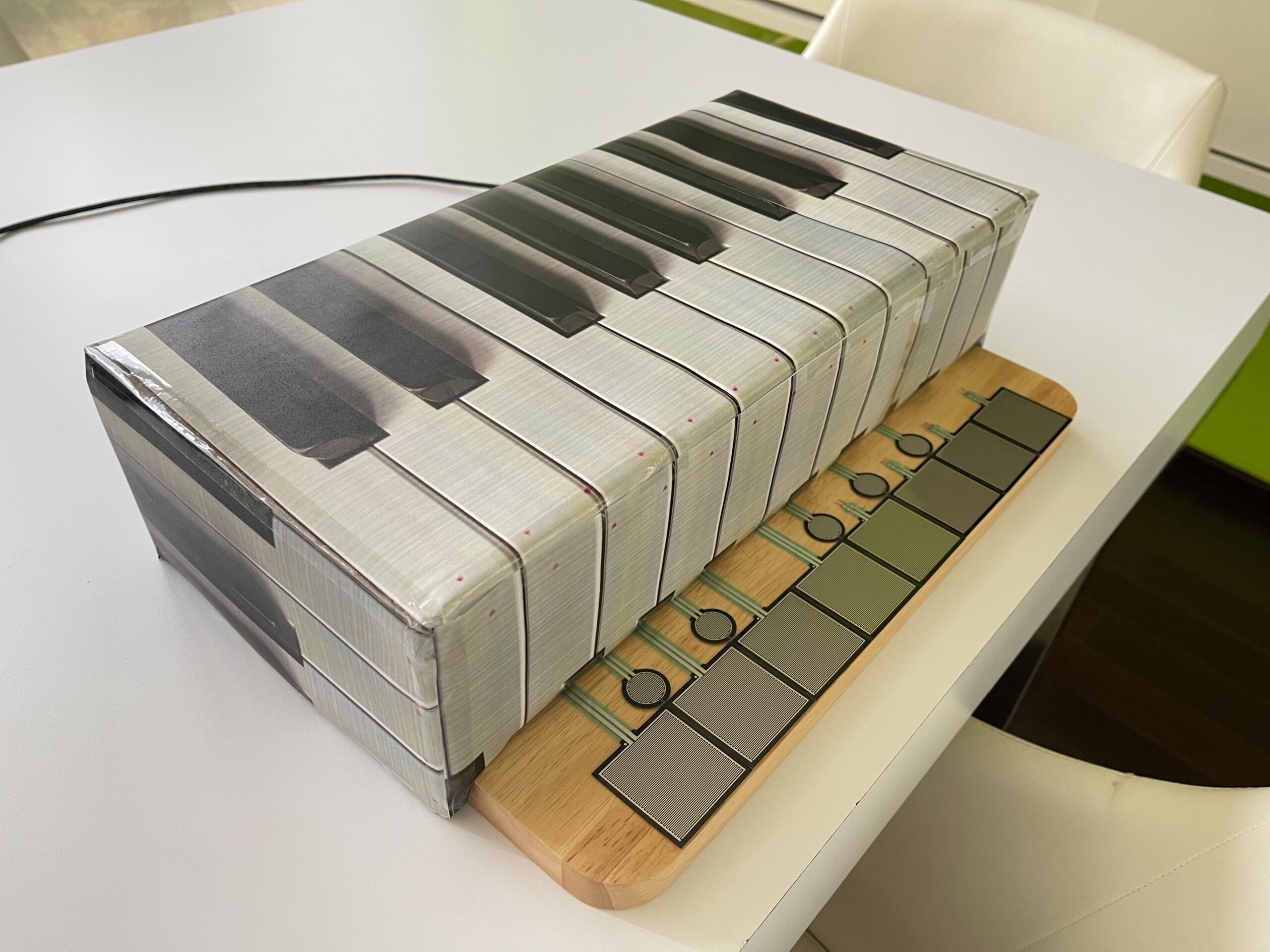
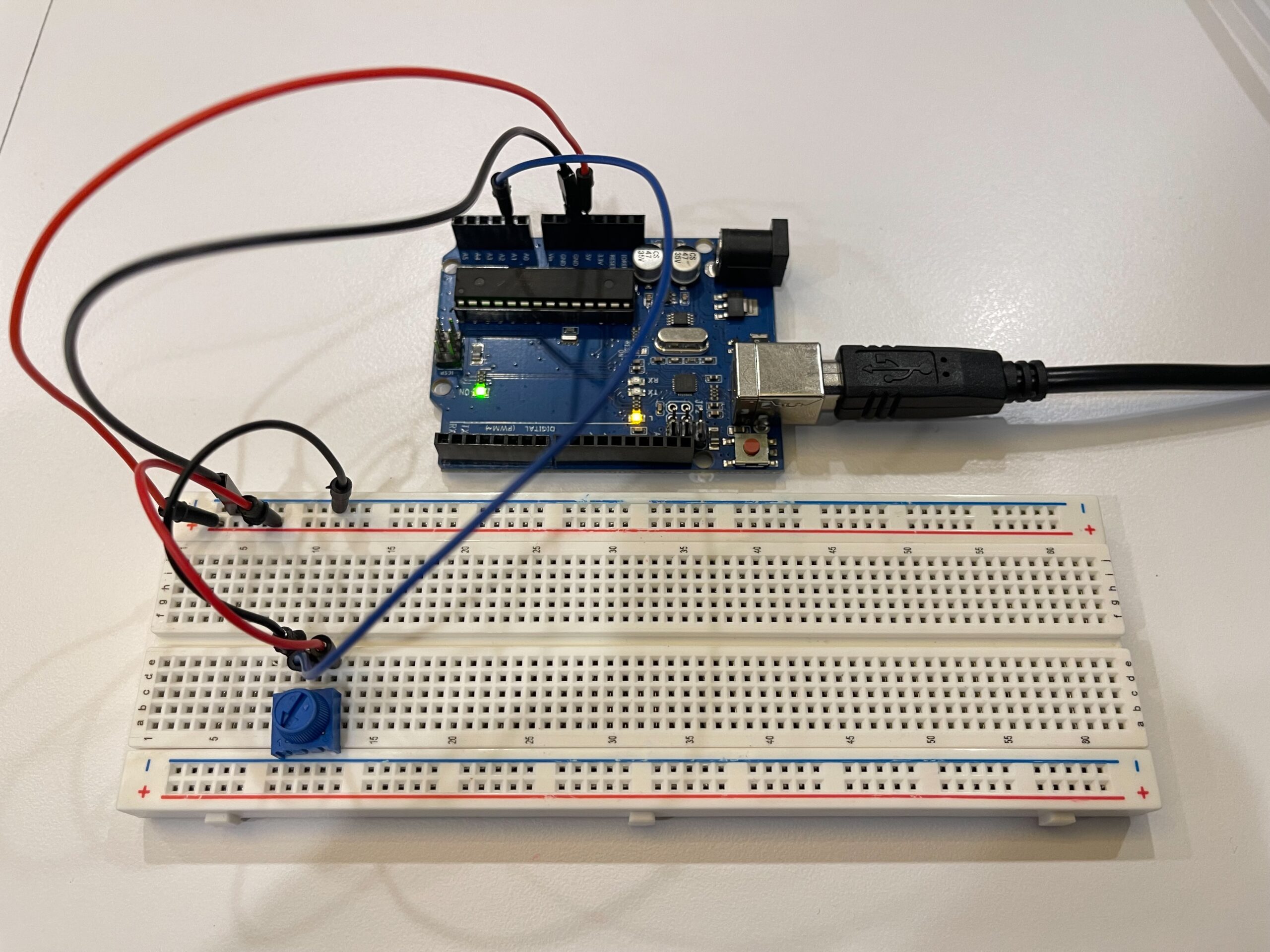
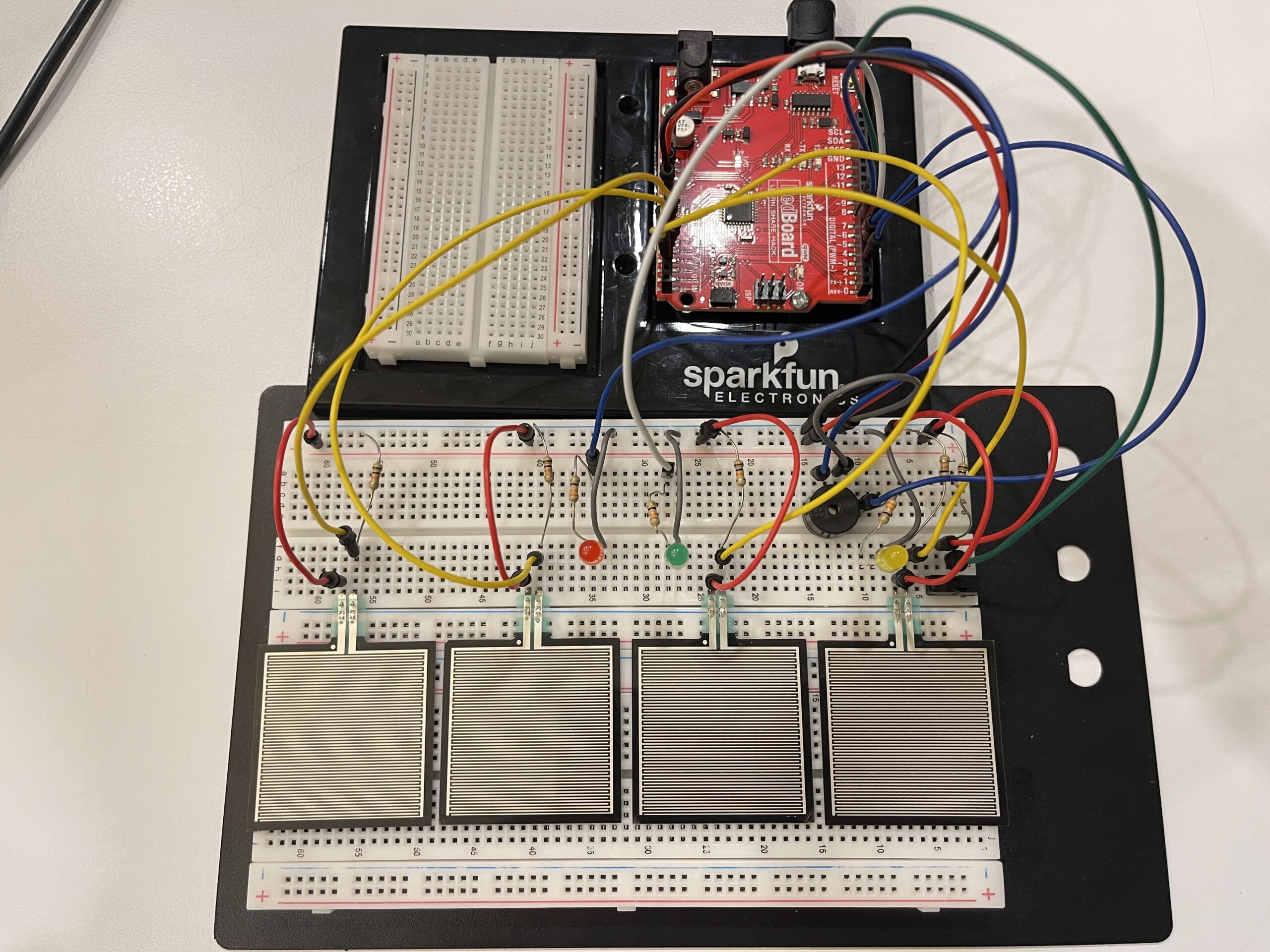
Pictures of Project:

VDO of project:

https://youtu.be/PZ8KxiPyQQQ?si=CkNlTvbEHZVMZ3Hm
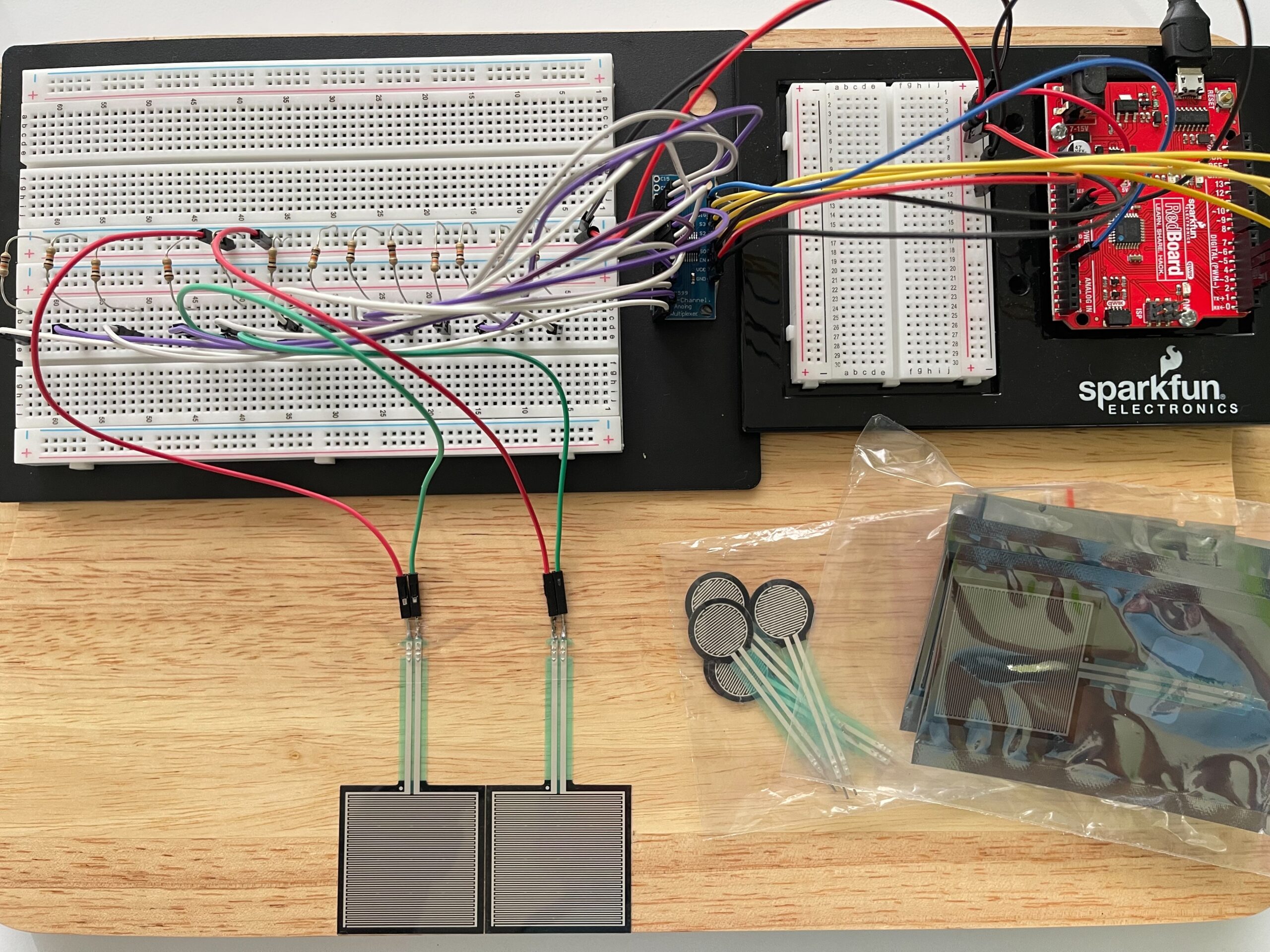
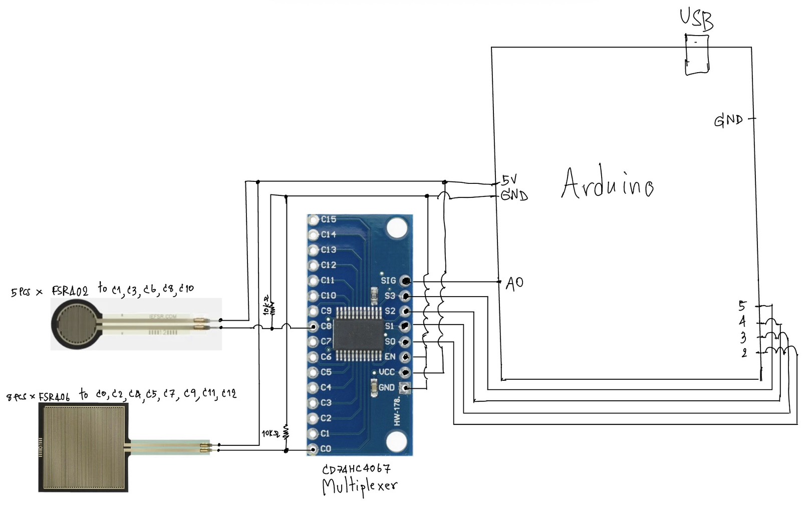
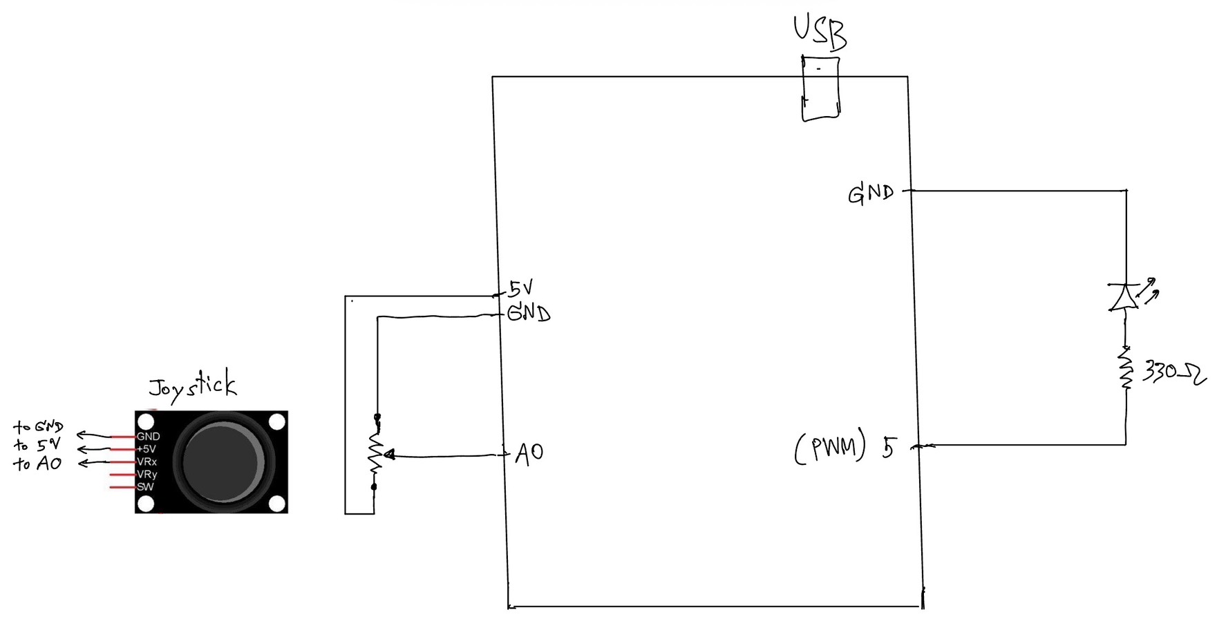
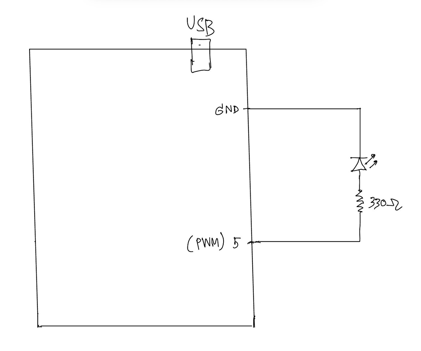
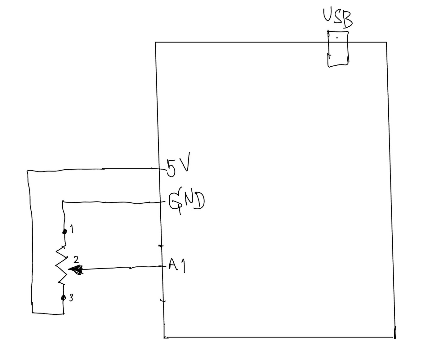
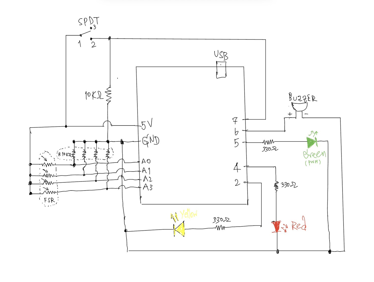
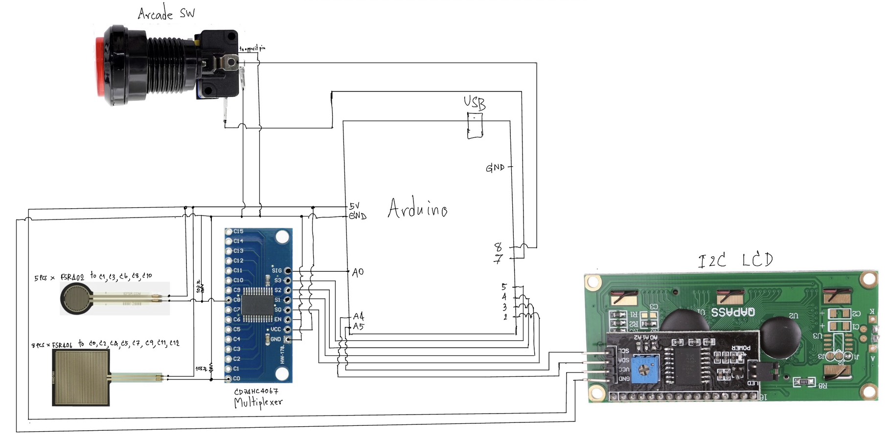
Schematic:

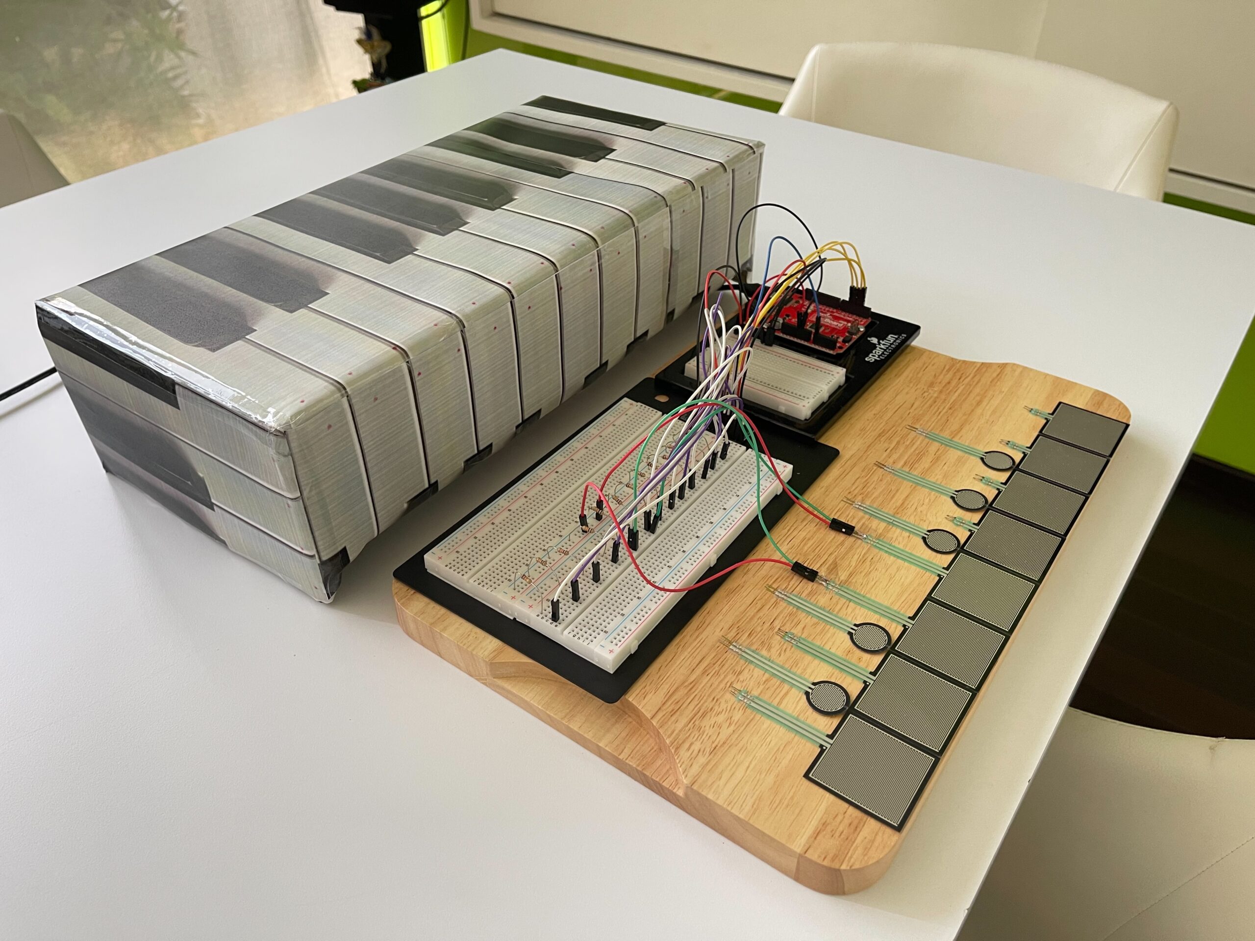
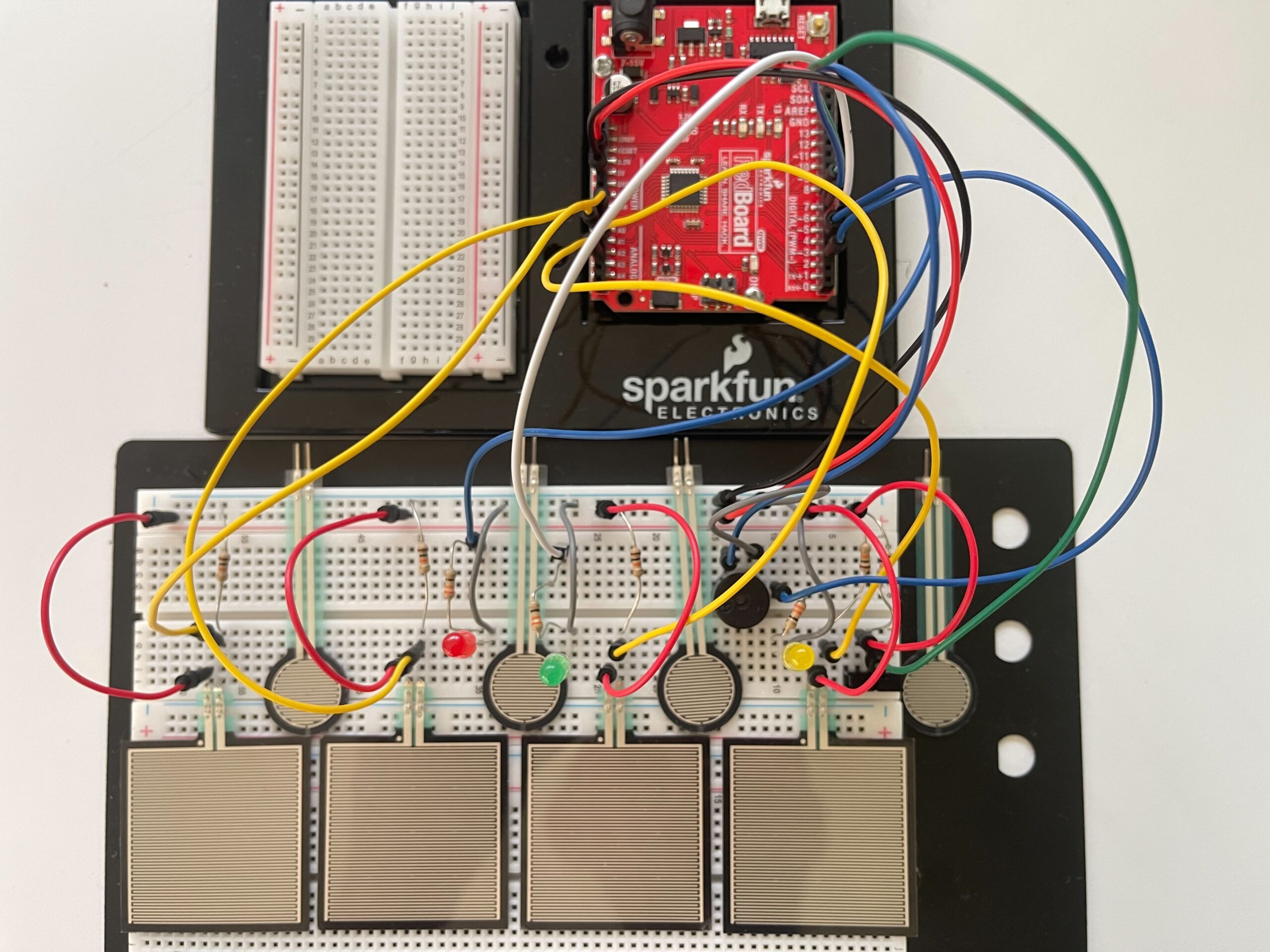
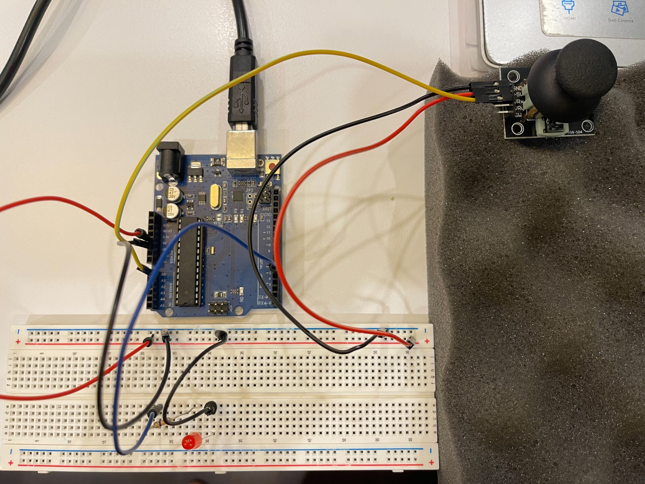
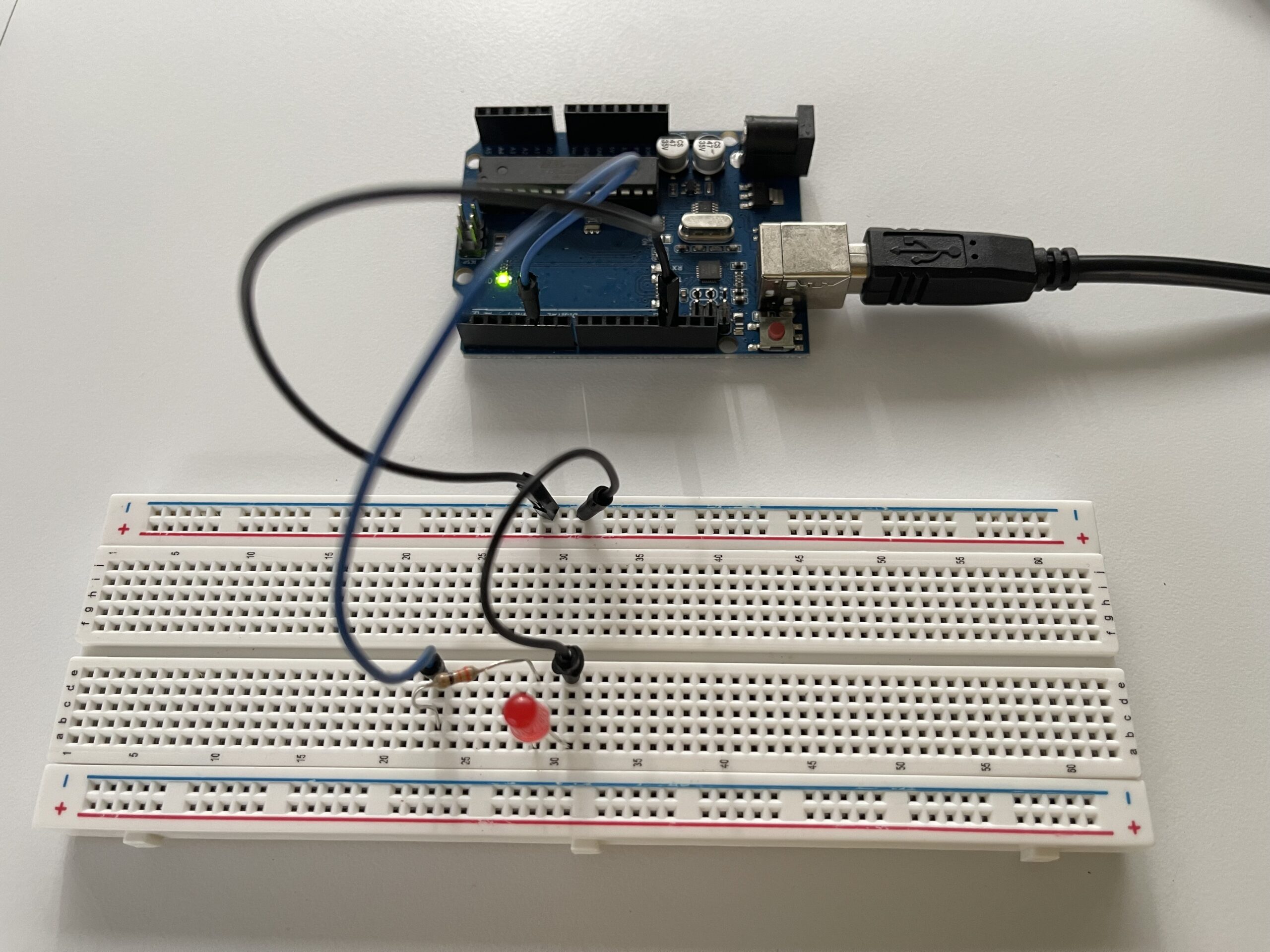
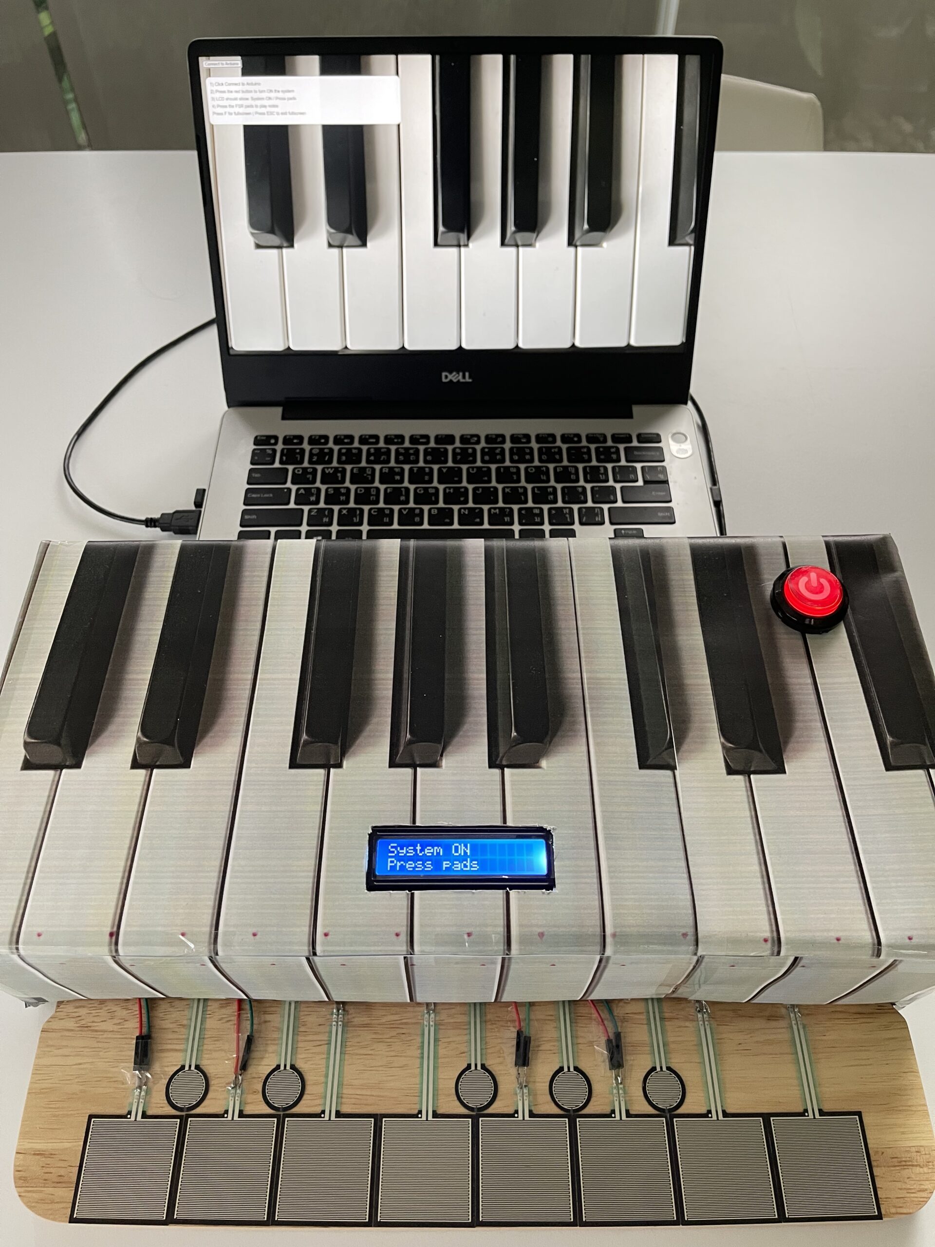
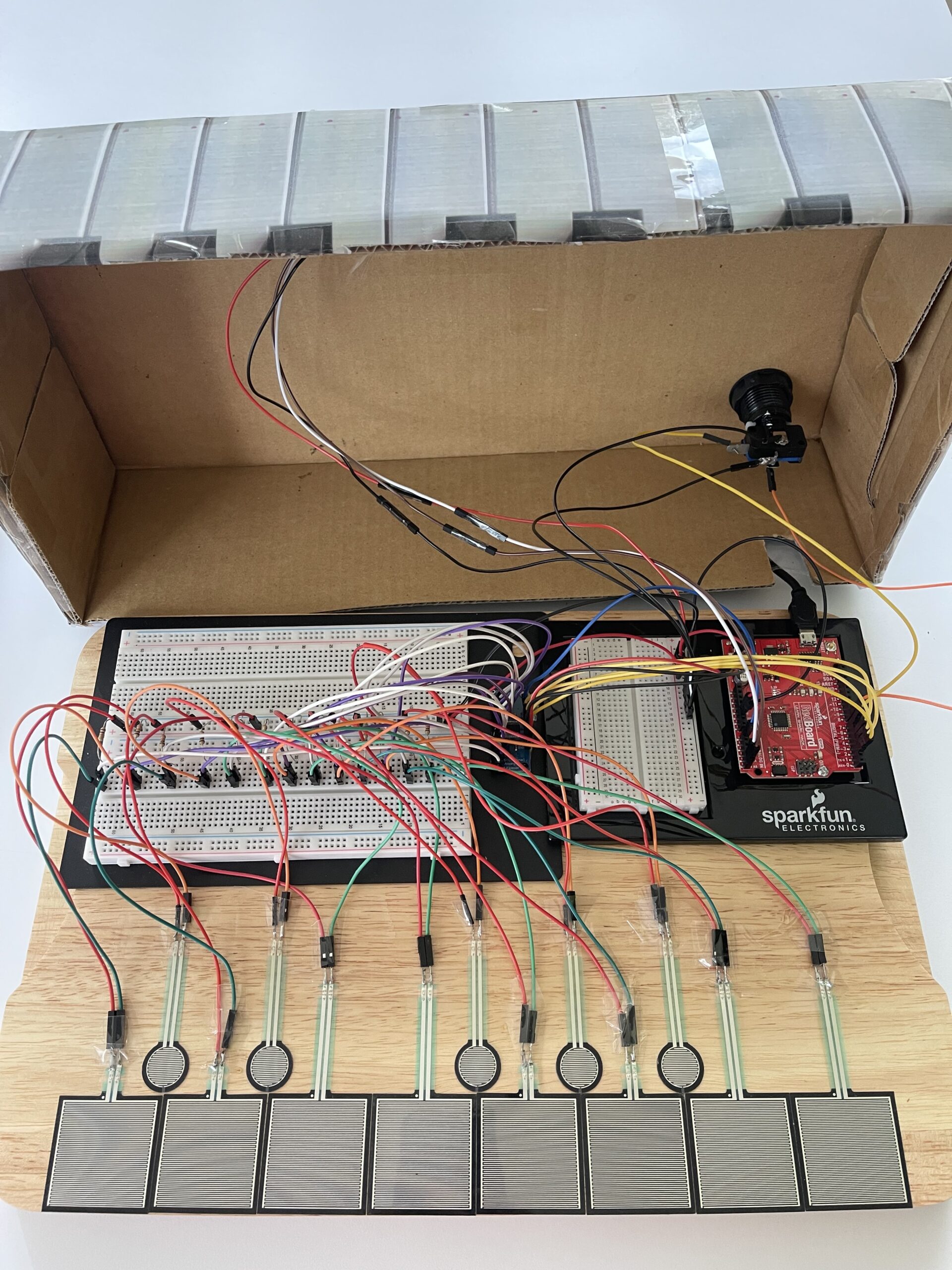
Wiring inside the cardboard box:

VDO of user testing(without giving any instruction):

https://youtu.be/GeI6QWZyzsk?si=tPqhPQI3fib59SSb


Interaction Design:

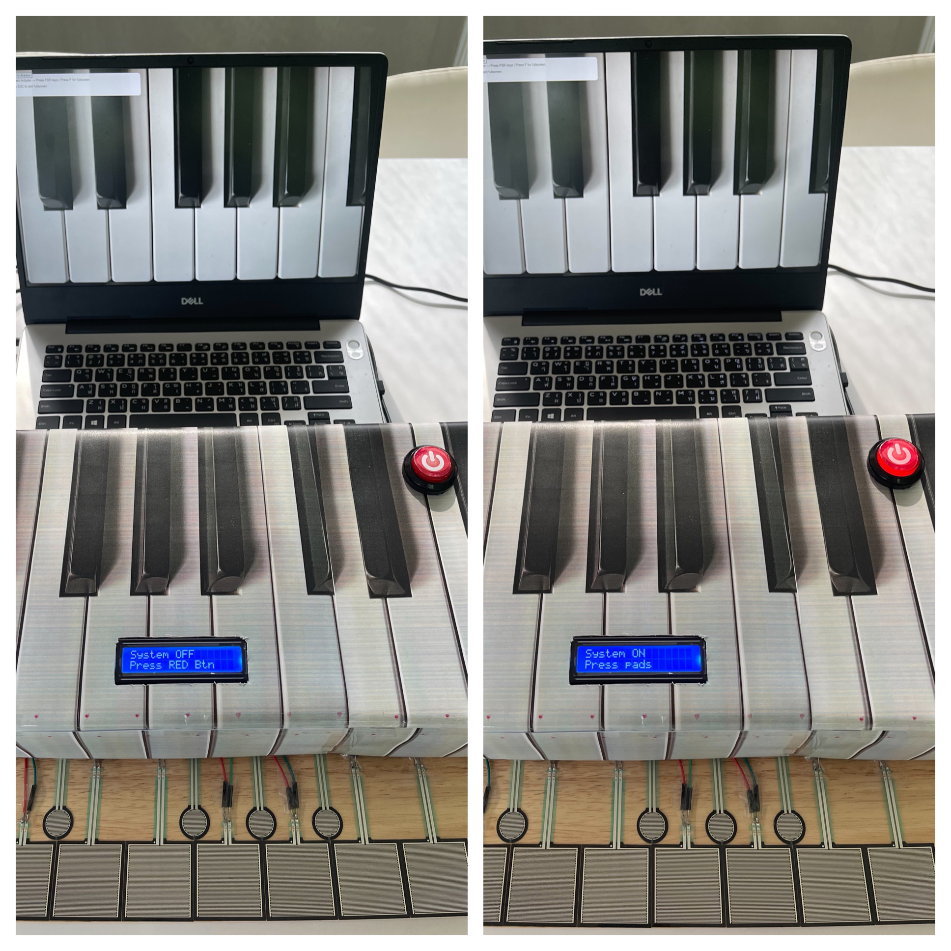
The interaction starts when the user presses the red arcade button. This turns the system ON, which is also shown on the LCD screen. The LCD then guides the user by displaying “Press pads”.

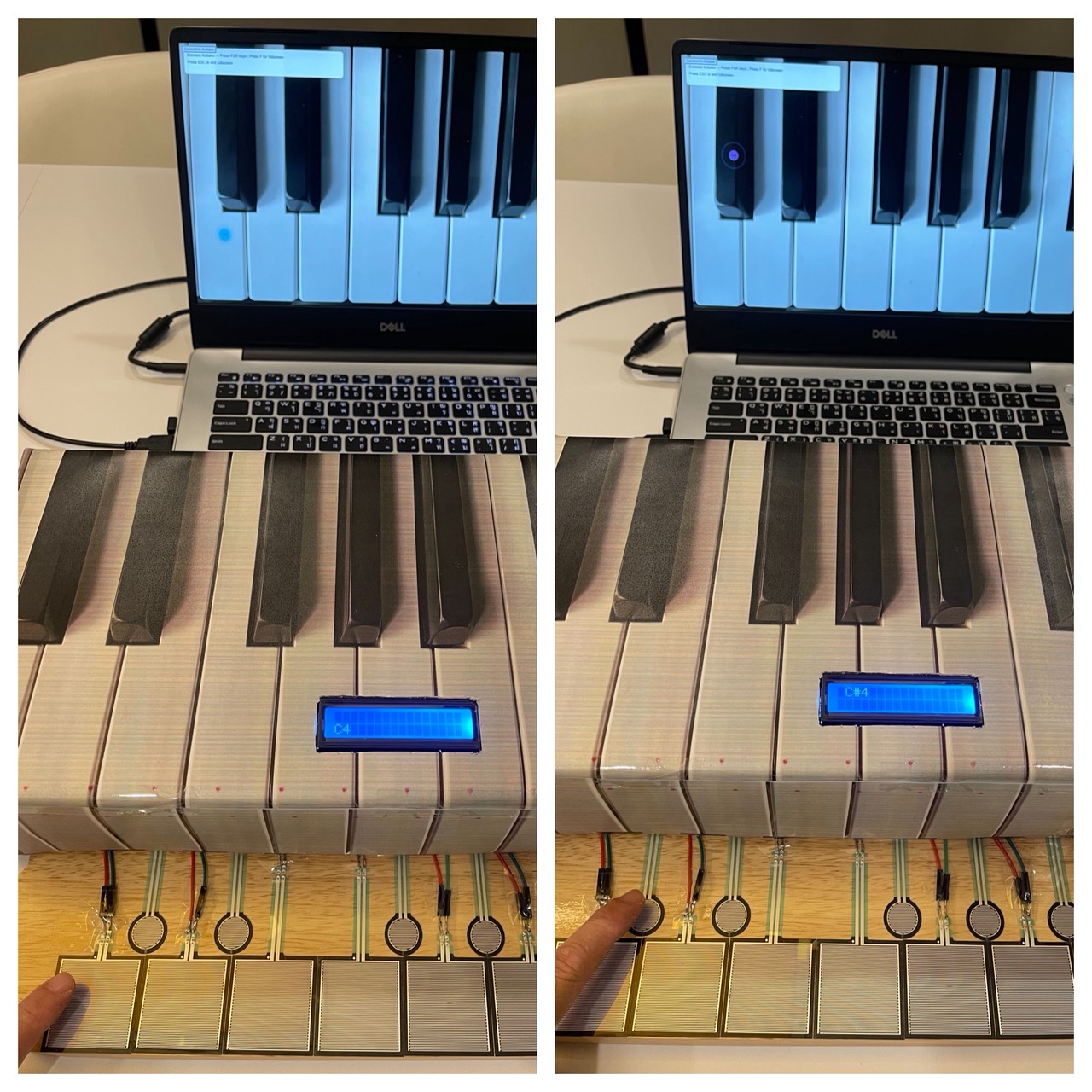
After that, the user can press any of the pressure sensors (FSR). Each sensor corresponds to a musical note (C4, D4, etc.). When a pad is pressed, the system sends the signal to p5.js, which plays a sound and shows a visual effect on the screen.

If no interaction happens for a few seconds, the system resets back to the default state, which helps new users understand what to do next.


Arduino code:

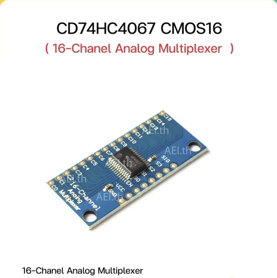
The Arduino is responsible for reading input from multiple FSR sensors using a CD74HC4067 multiplexer. This allows me to read many sensors using only one analog pin.

Each FSR is connected using a voltage divider with a resistor to produce stable analog values. The Arduino checks whether the value is above a threshold to determine if a pad is being pressed.

When a pad is pressed, the Arduino sends the index of the key through Serial communication to p5.js. It also receives note names back from p5.js and displays them on the I2C LCD screen.

The arcade button is used to control whether the system is ON or OFF, and the LED inside the button provides visual feedback.

Codes snippets:

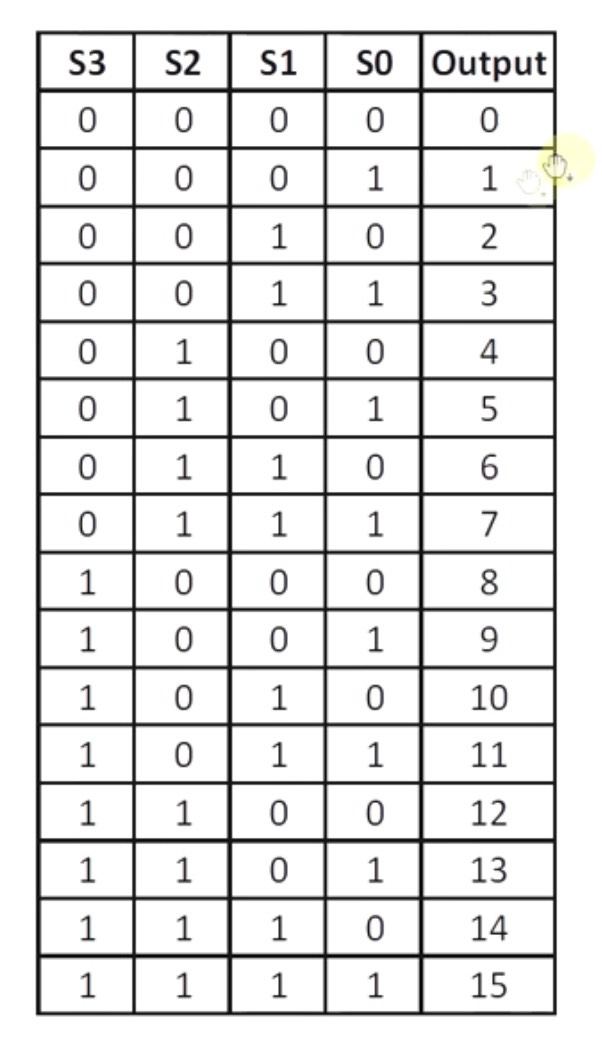
(1) Multiplexer reading

// Select channel on multiplexer
digitalWrite(S0, bitRead(channel, 0));
digitalWrite(S1, bitRead(channel, 1));
digitalWrite(S2, bitRead(channel, 2));
digitalWrite(S3, bitRead(channel, 3));

int sensorValue = analogRead(SIG);

This part selects which FSR is being read through the multiplexer and reads its analog value.

(2) Threshold logic

if (sensorValue > threshold) {
  Serial.println(channel);
}

This checks if a pad is being pressed and sends the index to p5.js.

(3) LCD display

lcd.setCursor(0, 0);
lcd.print("System ON");
lcd.setCursor(0, 1);
lcd.print("Press pads");

The LCD provides instructions to guide the user.

Arduino and p5.js GitHub:

https://github.com/skyorachorn/Intro-to-IM/tree/a7a5972712776f5ea0d3234a5193a3694f5a07d0/Final_Project


p5.js code:

The p5.js program receives data from Arduino using serial communication. When it receives a key index, it maps it to a specific note and plays the corresponding sound using an oscillator.

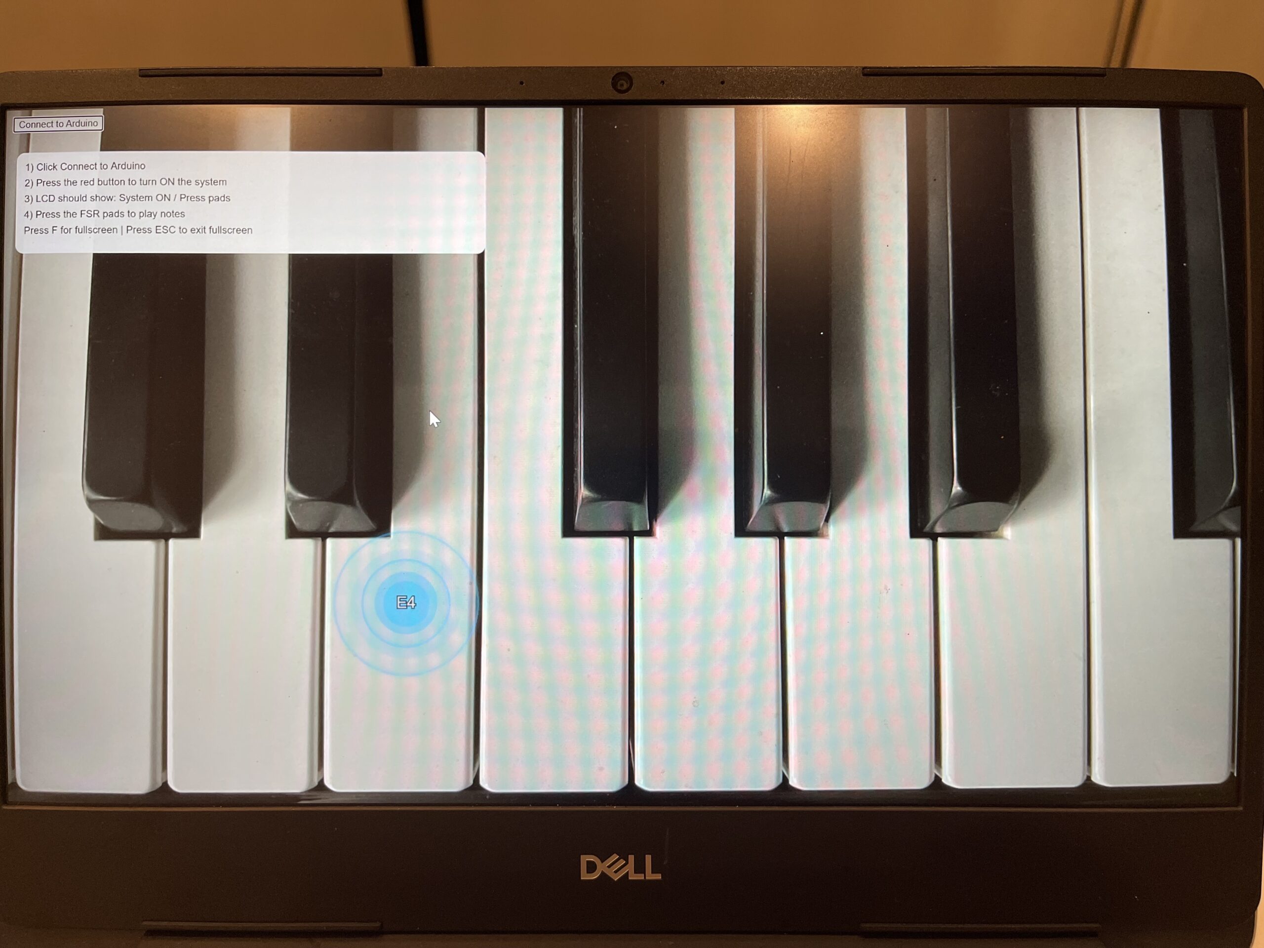
At the same time, a visual effect is generated at the position of the key. The visual consists of expanding circles with glow effects and fading animation.

I also added instructions on the screen to guide the user, especially for first-time interaction. The canvas is responsive and can switch to full screen mode for a better experience.

Codes snippets:

(1) Serial receive

let str = port.readUntil("\n");

if (str.length > 0) {
  let keyIndex = int(trim(str));
}

p5.js reads incoming data from Arduino.

(2) Trigger sound

osc.freq(note.freq);
env.triggerAttack(osc);

This plays the sound when a pad is pressed.

(3) Visual effect

balls.push({
  x: sx,
  y: sy,
  size: 28,
  alpha: 255
});

This creates the visual feedback on screen.

Communication between Arduino and p5.js:

The communication between Arduino and p5.js is done through Serial communication.

Arduino sends:
– Key index (0–12) when a pad is pressed
– -1 when the key is released

p5.js sends:
– The note name (e.g. C4, D#4) back to Arduino

This allows Arduino to display the correct note on the LCD screen while p5.js handles sound and visuals.


What I am proud of:

One part I am particularly proud of is how the physical and digital systems are connected together. The interaction feels responsive, and the combination of sound, visuals, and LCD feedback creates a complete experience.

I am also proud of the user guidance system using the LCD and on-screen instructions, which helps users understand what to do without needing verbal explanation.

Finally, I think the visual effects in p5.js improved the overall experience, making the interaction more engaging.
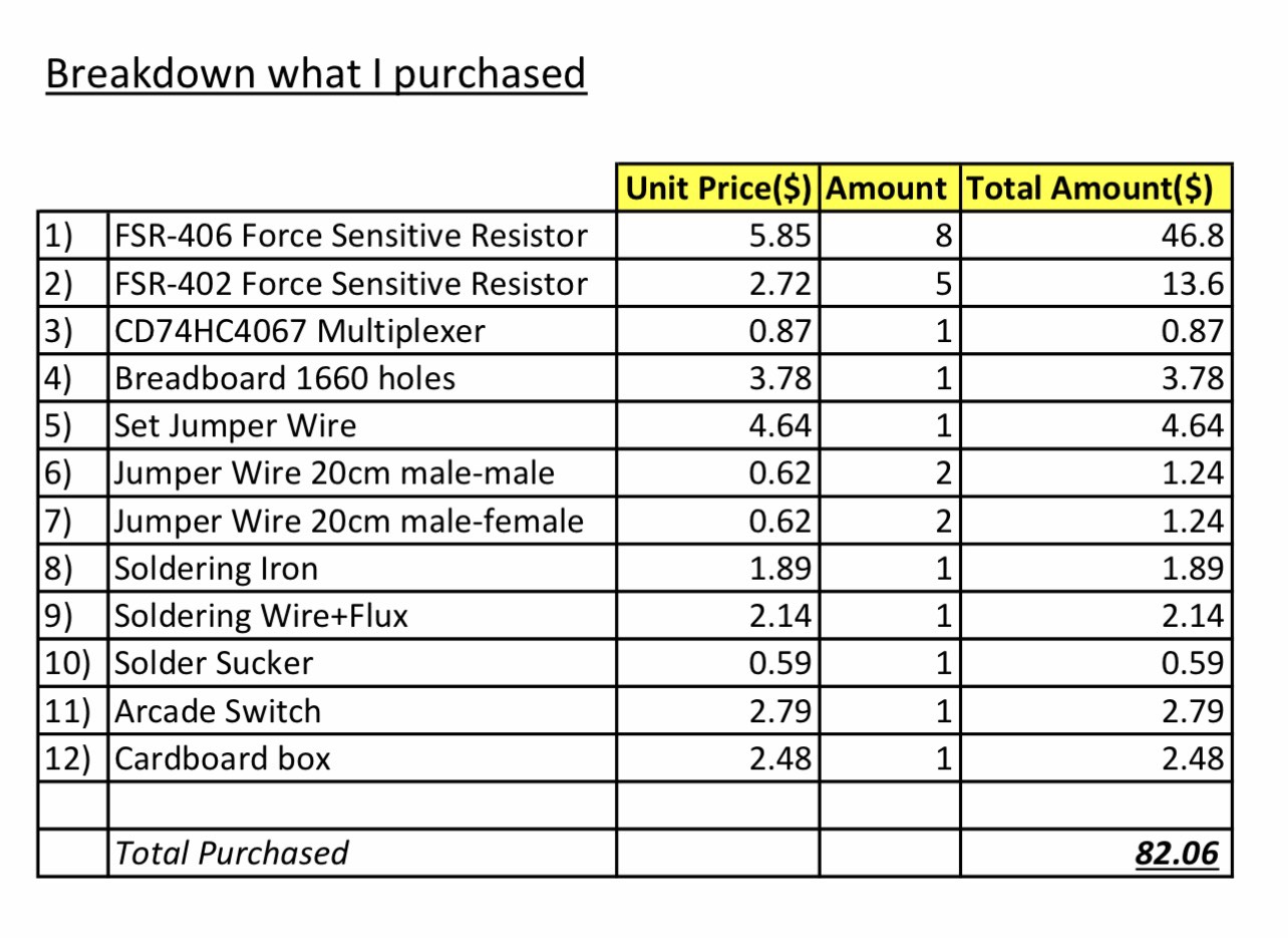
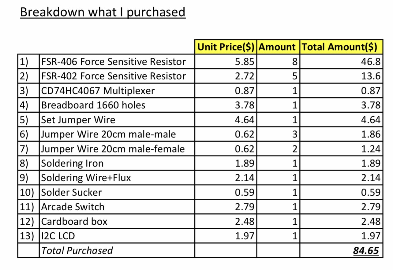
 

Breakdown cost:


Resources and References:

I used online resources such as YouTube tutorials to understand how to use the I2C LCD and arcade button wiring. I also referred to Arduino and p5.js documentation for serial communication and sound generation.

Some tutorials were used as references and then adapted to fit my project.

p5.js Sound Library (official reference)

https://p5js.org/reference/#/libraries/p5.sound

Basic FSR (Force Sensitive Resistor) guide
https://learn.adafruit.com/force-sensitive-resistor-fsr

Multiplexer(CD74HC4067)

https://learn.sparkfun.com/tutorials/multiplexer-breakout-hookup-guide

Multiplexer(CD74HC4067)

https://youtu.be/XAOo8DEbvck?si=oO7VKZ046IhJgHwh

Sounds

https://youtu.be/b_MMGJiUcbM?si=z7di2mc-pPGQBt1R

Triangle wave

https://kjh.ypj.mybluehost.me/glossary/triangular-wave/

I2C LCD

https://youtu.be/4o9VM7Nl9Os?si=hwz3Y6-QvSkRbGje

https://youtu.be/-jiHul1kQh4?si=WqZlRTMM3psv217o

https://youtube.com/watch?v=QIdERbxDVuM&feature=shared

Arcade button

https://youtu.be/Pkm8nRCSsIY?si=sFWSKIZpOXYXWQXT


AI assisting:

AI tools were used mainly to assist with debugging and improving code structure, especially for serial communication between Arduino and p5.js.

However, the overall design, concept, wiring, and implementation decisions were developed and tested by myself. I also modified and adapted any suggestions to fit my own project requirements.


Challenges:

One challenge was reading multiple FSR sensors reliably. Using a multiplexer required careful wiring and debugging to ensure each channel worked correctly.

Another challenge was the communication between Arduino and p5.js. At first, the data was inconsistent, but after adjusting the threshold and improving the logic, it became stable.

I also faced challenges in user experience, since users were initially confused about what to do. This led me to add instructions on the LCD and on the screen.


Future Improvements:

In the future, I would improve the design of the pads to be closer in size and spacing to a real piano keyboard, since some users mentioned that the pads felt too large.

I would also improve the visual system by making it more noticeable or adding more variation, so users might pay more attention to the screen.

Additional future improvement would focus on the hardware setup. The current prototype uses many exposed wires and breadboards, which can be messy and less stable. In the future, I would organize the wiring more cleanly and integrate the components into a more compact and durable enclosure.

Another improvement would be making the system wireless or more compact, instead of relying on a wired connection to a laptop.


Final Project – User Testing

PRESSYR – User Testing Reflection

VDO:

https://youtu.be/GeI6QWZyzsk?si=tPqhPQI3fib59SSb

For my final project, I created an interactive piano-inspired instrument called PRESSYR using Arduino, FSR pressure sensors, a CD74HC4067 multiplexer, an I2C LCD display, an arcade power button, and a p5.js visual and sound interface. The project allows users to press pressure-sensitive pads to play musical notes while also generating sound and visuals on a computer screen.

User Testing Process:

I conducted user testing with four participants. During the testing session, I intentionally did not give them detailed instructions at first because I wanted to observe how naturally they could understand and interact with the project on their own.

One thing I noticed immediately was that almost every participant was initially confused about what the device actually was. However, most of them could somewhat guess that it was related to a piano or music instrument because the cardboard enclosure visually resembled piano keys. In addition, my house already contains a real piano, and everyone who participated already knew that I play the piano, so this context may also have influenced their assumptions.

The main confusion at the beginning was understanding what to press first and how to start interacting with the system. Fortunately, the LCD screen helped guide users by displaying “Press RED Button” when the system was off. This instruction helped participants understand that the red arcade button was the actual starting point for interaction.

After turning the system on, some participants were still slightly confused about what to do next. I think this happened for two reasons. First, the instructions on the LCD were written in English, and second, some participants did not immediately understand what the word “pads” referred to. Even so, after a short moment of exploration, every participant eventually understood that the pressure-sensitive pads were musical inputs that played notes like Do, Re, Mi, Fa, Sol, La, Ti, Do.

Observations During Interaction:

One interesting observation from the testing session was that participants rarely looked at the computer screen visualizations while playing. Instead, they focused almost entirely on the physical pads and their hand movements.

I believe this happened mainly because users had to concentrate on pressing the pads accurately and listening to the melody from each key being produced. Since the sound feedback already confirmed that the interaction was working, participants did not feel a strong need to constantly look at the screen. The laptop screen was also positioned slightly farther away from the pads, which may have reduced visual attention even more.

Although it is possible that the visual effects on the screen were not large or attention-grabbing enough, I personally think the stronger reason was that users naturally prioritized the physical interaction and audio feedback over the visual component.

What Worked Well:

Several aspects of the project worked successfully during testing:

– The arcade power button clearly communicated the ON/OFF state of the system.
– The illuminated LED inside the arcade button provided immediate visual feedback.
– The LCD instructions helped guide users through the interaction process.
– The pressure-sensitive pads successfully triggered sound and visuals consistently.
– Users eventually understood the interaction flow without requiring direct explanation.
– The piano-inspired physical design helped communicate the musical concept of the project.

Areas for Improvement:

Some participants commented that the pressure pads felt larger than actual piano keys. This feedback was valuable because it highlighted how the scale of the interaction affected the realism of the experience.

In future versions of the project, I would like to:
– Reduce the size of the pads to better resemble real piano keys.
– Improve the visual prominence of the p5.js animations so users notice them more easily.
– Add clearer visual labels or symbols for first-time users.
– Experiment with different layouts and materials for a more polished interaction experience.
– Explore using velocity-sensitive audio or multiple sound layers for more expressive musical interaction.

Reflection:

This user testing session helped me realize how important clarity and interaction flow are in physical computing projects. Even though the project technically functioned correctly, small design decisions such as wording, placement of instructions, and physical scale strongly affected how users understood the experience.

Overall, the testing process was extremely useful because it revealed areas where the interaction was intuitive and areas where users still needed additional guidance. It also helped me think more carefully about how people naturally approach unfamiliar interactive objects for the first time.

Final Project – Finalized Concept and Progress


Pressure-Based Digital Musical Instrument – Progress Update

For my final project, I am developing a physically interactive digital musical instrument that combines Arduino and p5.js. The main idea is to simulate a small piano-like interface using pressure sensitive sensors (FSRs) as keys. Each key corresponds to a musical note, and when pressed, it triggers both the sound and visual feedback on the computer.

The system is designed to feel closer to a real instrument rather than just a simple button interface. Instead of using traditional push buttons, I chose Force Sensitive Resistors (FSR406 for white keys and FSR402 for black keys) so that the interaction feels more natural when placing fingers on the surface.

The project also includes a visual component in p5.js, where each note triggers a graphical response (such as expanding shapes or bursts) aligned with the keyboard layout.


Arduino System Design (Input & Output)

On the Arduino side, the main responsibility is to read input from multiple FSR sensors and send that data to p5.js through serial communication.

Since I am using 13 keys (8 white + 5 black), I needed a way to expand the number of analog inputs. To solve this, I am using a CD74HC4067 multiplexer, which allows me to read multiple sensors using a single analog pin.

Inputs

* 8 × FSR406 (white keys)
* 5 × FSR402 (black keys)

Each FSR is connected through the multiplexer channels (C0–C12). The Arduino cycles through each channel, reads the analog value, and determines whether a key is being pressed based on a threshold.

Processing

* Scan each multiplexer channel
* Detect press events (based on pressure threshold)
* Map each sensor to a note index

Outputs (to p5.js)

* Sends serial data representing which key is pressed
(e.g., key index or note trigger)


p5.js System Design (Sound & Visual Output)

The p5.js side handles both sound synthesis and visual feedback.

Input from Arduino

* Receives serial data from Arduino (note index or trigger)
* Interprets incoming data as note events

Sound Output

* Uses p5.sound to generate tones
* Each note is mapped to a frequency (C4 → C5 range)
* Oscillator is used to produce sound (triangle waveform for smoother tone)

Because of browser audio restrictions, the user must click once on the screen before sound can play. This is an important part of the interaction design.

Visual Output

* Background image of a piano keyboard is displayed
* When a note is triggered:
* A visual “burst” or circle appears at the corresponding key position
* The animation fades out over time

This creates a synchronized audio-visual experience.


System Interaction Flow

Overall system flow:

1. User presses an FSR key
2. Arduino reads the sensor via multiplexer
3. Arduino sends note data through serial
4. p5.js receives the data
5. Sound is generated
6. Visual feedback appears on screen

This creates a continuous loop of input → processing → output.


Current Progress

So far, I have:

* Set up the basic circuit with some FSR sensors and breadboard
* Soldered to connect and tested the CD74HC4067 multiplexer
* Implemented initial Arduino code to read multiple inputs
* Keyboard mapping
* Sound generation
* Visual feedback system
* Tested interaction using keyboard input as a temporary replacement for hardware input

* Make cardboard box to cover and protect wirings

VDO of Current Progress:

On Arduino side, only test Voltage-Divider on 2 FSRs to see the correct circuit and their threshold and on p5 side only test sound oscillator and visual effect by computer keyboards

https://youtu.be/MlDVwkXKKx0?si=0aQA0kxDGdNnhAR8

Github of testing FSR:

https://github.com/skyorachorn/Intro-to-IM/blob/b0862f67a54b640df9c8442db31b8cd9b5a48c83/Test_FSR.ino

p5:

I have also started integrating real sensor input, though I am still refining the stability of readings and mapping.


Diagram:

Next Steps

For the next stage of development, I plan to:

* Fully integrate all 13 FSR inputs with stable readings
* Improve serial communication between Arduino and p5.js
* Add the arcade switch as a system control (on/off interaction)
* Refine visual feedback to better align with physical key positions
* Shorter components such as resistors to avoid short circuit


Reflection

One challenge so far has been managing multiple inputs with limited Arduino pins, which is why the multiplexer became an important part of the design. Another challenge is balancing hardware reliability with software responsiveness.

At the same time, combining Arduino and p5.js has made the project more interesting, since it allows both physical interaction and digital visualization.


References:

https://youtu.be/b_MMGJiUcbM?si=z7di2mc-pPGQBt1R

https://youtu.be/XAOo8DEbvck?si=oO7VKZ046IhJgHwh

https://kjh.ypj.mybluehost.me/glossary/triangular-wave/

Final Project: Pressure-Based Digital Musical Instrument

Preliminary Concept: Pressure-Based Digital Instrument

For my final project, I plan to create a physically interactive musical instrument using Arduino and p5.js. The idea is to build a simple keyboard-like interface where users can play notes by touching pressure sensors.

Instead of using buttons, I will use Force Sensitive Resistors (FSRs) so that the interaction feels softer and more natural, similar to placing fingers on a piano. Each sensor will represent one note (C, D, E, F, G, A, B, C, including sharps/flats).   Below picture will have only 4 FSR406 and 4 FSR402, I will buy them more and also 16 channel analog multiplexer to complete my project soon. 

Arduino will read the sensor values and send the data to p5.js through serial communication. In p5, the input will be used to generate sound and simple visual feedback. I will use the computer’s speaker for audio output instead of a buzzer to improve sound quality.

Since I need to use multiple sensors, I will use a CD74HC4067 multiplexer to expand the number of inputs. This allows Arduino to read many FSRs efficiently.

The system will also include a feedback loop. For example, when a note is played, p5 can send a signal back to Arduino to turn on an LED. This creates a simple two-way communication between Arduino and p5.

The goal of this project is to explore how physical touch can be translated into digital sound and visual feedback in a clear and responsive way.


Inspiration

This project is inspired by different types of interactive musical interfaces:

* Digital MIDI controllers and touch-based instruments
* Piano keyboards, especially the idea of soft and responsive touch
* Interactive installations where physical actions directly control sound
* Simple expressive systems that focus on user interaction rather than complexity

I am particularly interested in how small physical gestures, like lightly touching a surface, can create meaningful digital outputs such as sound.


References / Tutorials

Here are some references and tutorials that informed my idea:

* p5.js Sound Library (official reference)

https://p5js.org/reference/#/libraries/p5.sound

* Basic FSR (Force Sensitive Resistor) guide
https://learn.adafruit.com/force-sensitive-resistor-fsr

* Multiplexer (CD74HC4067) explanation
https://learn.sparkfun.com/tutorials/multiplexer-breakout-hookup-guide


Sketch Description

The system will be arranged like a simple keyboard:

* FSR406 → white keys (main notes)
* FSR402 → black keys (sharps/flats)

Reading Reflection – Week 9 Design meets disability

Reading Design Meets Disability made me rethink what I previously considered “good design.” I used to associate good design with aesthetics and general usability, but this reading challenged my assumption by showing how design is deeply tied to social attitudes toward disability. The section on “discretion” stood out to me, where assistive devices like hearing aids are designed to be hidden in order to avoid stigma. This made me question whether invisibility is actually a positive goal, or if it reinforces the idea that disability should be concealed. I found myself reflecting on how design choices are not neutral and that they reflect cultural values about what is considered “normal.” The tension between fashion and disability also left a strong impression on me. While making assistive devices more fashionable can empower users, it also risks emphasizing appearance over accessibility. This contradiction made me realize that design often operates between competing goals rather than clear solutions.

This reading also connected to my previous understanding of user-centered design but expanded it in a way I had not considered before. It made me realize that “the user” is often imagined as a narrow, able-bodied group, which doesn’t take into account many real experiences. The idea of “simple meets universal” raised an important question for me that is it actually possible to design something that works for everyone, or does inclusivity inevitably introduce complexity?   This challenges the assumption that simplicity is always better. Personally, this reading shifted my perspective from seeing design as purely functional problem-solving to understanding it as a more cultural and ethical practice that shapes how people are perceived and included. It also made me more aware of the limitations in the designs I encounter daily and how they really reflect broader biases rather than just technical decisions.

Week 11 Ex03 Bi-Directional Communication

Github:

https://github.com/skyorachorn/Intro-to-IM/blob/5c35d686b16c8ad6965f1755d6dd0e0c786ab2c4/Ex03_Bi_Directional_Com.ino


Youtube:

https://youtu.be/9bqEiR_zGJM?si=Mm7S7kV4fjWl15sk

Circuit:


Hand Written Circuit:

In this exercise, we extended our work from the previous tasks by implementing bi-directional communication between Arduino and p5.js. The goal was to use an analog sensor to control the wind force in a physics simulation, and at the same time send data back from p5 to Arduino to control an LED.

We started from the gravity and wind example provided in class and kept the structure mostly unchanged. Instead of using keyboard input to control the wind direction, we replaced it with a joystick connected to Arduino. The horizontal axis of the joystick was read using analogRead() and sent to p5 through serial communication.

On the p5 side, the incoming value was read using port.readUntil(“\n”), then converted into an integer. We mapped this value to a range between -1 and 1, which was used as the horizontal wind force. As a result, moving the joystick left or right directly influenced the movement of the ball in the simulation.

To complete the bi-directional interaction, we added a simple condition in p5 to detect when the ball bounces on the ground. Whenever a bounce occurs, p5 sends a value back to Arduino. On the Arduino side, this value is read using Serial.parseInt(), and the LED is turned on or off accordingly.

This allowed us to create a system where Arduino sends sensor data to p5, and p5 responds by sending control signals back to Arduino.

What We Learned:

* How to implement bi-directional serial communication
* How to use an analog sensor (joystick) to control a physics simulation
* How to send control signals from p5 back to Arduino
* How physical and digital systems can interact in both directions

Code I’m Proud Of:

One part we are particularly satisfied with is how the system detects a meaningful bounce and avoids triggering unnecessary signals.

p5.js (bounce detection + sending data)

let bounced = 0;
  let floorY = height - mass / 2;

  // bottom bounce
  if (position.y > floorY) {
    position.y = floorY;

    if (velocity.y > 2) {
      velocity.y *= -0.9;
      bounced = 1;
    } else {
      velocity.y = 0;
    }
  }

  // send LED state back to Arduino
  if (port.opened()) {
    port.write(bounced + "\n");
  }

This section is important because it defines what counts as a “real” bounce. By using a velocity threshold, we ensure that only stronger impacts trigger the LED, while small movements at the ground are ignored.

Arduino (receiving and controlling LED)

int ledState = Serial.parseInt();

    if (Serial.read() == '\n') {
      digitalWrite(ledPin, ledState);
    }

This part connects the digital signal from p5 to a physical output. It shows how a simple value sent through serial communication can directly control hardware.

Challenges:

One issue we encountered was that the LED flickered rapidly when the ball reached the ground. Even though the ball appeared to be at rest, the system continued to detect small movements due to gravity and drag.

At first, this made the LED stay on or flicker continuously, which was not the intended behavior.

To solve this, we introduced a simple velocity threshold. Instead of triggering a bounce whenever the ball touched the ground, we only considered it a valid bounce when the downward velocity was greater than a certain value. After testing, we found that using a condition of velocity.y > 2 provided a stable and clear result.

This helped us better understand how physics simulations can produce small continuous movements, and why additional conditions are sometimes needed to define meaningful events.

Future Improvements:

If we were to continue developing this project, we would consider:

* Adding a dead zone to the joystick to reduce unwanted drift
* Using both axes of the joystick to control more complex motion
* Adding more LEDs or outputs to represent different events
* Improving the visual feedback to better match the physical response


Reference:

https://youtu.be/6LkqhQ1-vJc?si=E_jhX4XUAnMQBCrY

https://youtu.be/pD2JUNUWJGU?si=xgiGR7X3Bhdkyi6W

Week 11 Ex02 P5 to Arduino Communication


Github:

https://github.com/skyorachorn/Intro-to-IM/blob/0f3767a9cc4fe21946d8b84a76a020a09abacbbd/Ex02_P5_to_Arduino_Com.ino


Youtube:

https://youtu.be/BT8Y9AafPIk?si=77WJciHPNwpz8n2J


Picture of Circuit:

Hand Written Diagram:

In this exercise, we explored serial communication in the opposite direction, from p5.js to Arduino. The main objective was to control the brightness of an LED on Arduino using an interaction created in p5.

We again started from the class example and kept the overall structure close to what was introduced by professor Aya. However, for this exercise, we simplified the communication so that p5 sends only one value instead of multiple values. This made it easier to focus on the main idea of sending data from the browser to Arduino.

On the p5 side, we used the p5.webserial library and the same button-based connection method as in the previous exercise. Once the serial connection is opened, p5 continuously sends a brightness value based on the horizontal position of the mouse. This value is mapped into a range between 0 and 255, which matches the range used by analogWrite() on Arduino.

On the Arduino side, we used Serial.parseInt() to read the incoming integer sent from p5. After checking for the newline character \n, the value is applied to an LED connected to a PWM pin. This allows the LED to gradually brighten or dim instead of simply turning on and off.

This exercise helped us better understand how p5 can be used not only to receive data from Arduino, but also to actively control physical outputs on the hardware side. Compared to Exercise 01, this made the communication feel more interactive because the browser was no longer only displaying data, but also sending instructions back to Arduino.

Through this process, we gained a clearer understanding of how serial data can be used to control physical output in real time, and how important it is for both the code structure and the wiring to match the intended behavior.

What We Learned:

* How to send data from p5.js to Arduino through serial communication
* How to use Serial.parseInt() on the Arduino side
* How to control LED brightness with analogWrite()
* How browser-based interaction can directly affect hardware output

Code I’m Proud Of:

One part we are particularly satisfied with is how the p5 sketch and Arduino sketch work together to control LED brightness in real time. This section clearly shows how a visual interaction in the browser becomes a physical output on the Arduino side.

p5.js (sending brightness value)

let brightness = int(map(mouseX, 0, width, 0, 255));
  brightness = constrain(brightness, 0, 255);

  // show the current value on screen
  fill(brightness);
  rect(100, 150, 200, 100);

  fill(0);
  textSize(16);
  text("Brightness: " + brightness, 120, 130);

  if (port.opened()) {
    port.write(brightness + "\n");
  }

This part is meaningful because it translates a simple mouse movement into a numerical value that can be understood by Arduino. It also helped us see how p5 can act as the controlling side of the communication.

Arduino (receiving + controlling LED)

int brightness = Serial.parseInt();

    if (Serial.read() == '\n') {
      analogWrite(ledPin, brightness);
    }

We found this section especially important because it shows how Arduino receives a value from p5, processes it, and immediately applies it to a physical output. In this case, the output is the LED brightness controlled through PWM.

Problems We Encountered:

One issue we encountered was that the LED did not appear to brighten or dim smoothly at first. Even though the value on the p5 side was clearly changing, the LED response did not look correct. After checking both the code and the circuit, we realized that the LED needed to be connected to a PWM pin in order for analogWrite() to work as expected. Once we moved the LED to the correct pin, the brightness control became much more visible.

Another thing we paid attention to was keeping the communication format simple. Since this exercise only required brightness control, we kept the message to a single value followed by a newline character. This made the program easier to understand and reduced confusion while testing.

Future Improvements:

If we were to continue developing this exercise, we would consider:

* Replacing mouse control with a more interesting p5 interaction, such as dragging, key presses, or etc.
* Adding multiple LEDs and sending more than one value from p5
* Expanding the system into bi-directional communication so Arduino could also send sensor data back to p5
* Improving the visual design in p5 so that the screen feedback more closely matches the physical LED behavior

Week 11 Ex01 Arduino to P5 Communication

Github:

https://github.com/skyorachorn/Intro-to-IM/blob/38f5a920179feadd602c862571956198fbb9e0cf/Ex01_Arduino_to_P5_Com.ino


Youtube:

https://youtu.be/dvRseX6c4VU?si=mKZLcT-Lm9T1LGMQ

Handwritten Diagram:

Picture of Circuit:

In this exercise, we explored serial communication between Arduino and p5.js. The main objective was to use a single sensor on Arduino and translate its input into visual movement in p5, specifically controlling an ellipse moving horizontally across the screen.

We began by following the example demonstrated in class and gradually adapted it to better understand the data flow. On the Arduino side, we used a potentiometer as an analog input. The sensor value (0–1023) was mapped to a smaller range (0–255) before being sent through the serial port using Serial.println(). This ensured that the data could be easily interpreted on the p5 side.

For p5.js, we adopted the structure introduced by professor Aya using the p5.webserial library. The connection process is handled through a button (connectBtn), and the serial port is opened using port.open(baudrate). This approach helped us clearly understand how communication between Arduino and the browser is initiated manually rather than automatically.

Inside the draw() loop, we used port.readUntil(“\n”) to read incoming serial data line by line. The received string is then cleaned and converted into a number using trim() and int(). We then used map() to convert this value into a position across the canvas width. As a result, the ellipse moves smoothly from left to right, and when the input value decreases, it naturally moves back from right to left, creating a responsive and continuous motion.

Through this process, we gained a clearer understanding of how physical input can directly influence digital visuals in real time. It also highlighted the importance of consistent data formatting and timing in serial communication.

What We Learned
• How to send analog data from Arduino using Serial.println()
• How to receive and interpret serial data in p5.js
• How to map sensor values into visual output
• How hardware and software can interact in real time

Code I’m Proud Of

One part we are particularly satisfied with is how the sensor data is processed and translated into visual movement. This section demonstrates how raw data from Arduino becomes meaningful interaction in p5.

int potentiometer = analogRead(A1);

 // map the value from 0-1023 to 0-255
 int mappedPotValue = map(potentiometer, 0, 1023, 0, 255);

 // send value to p5 as a string with newline
 Serial.println(mappedPotValue);

This part is important because it simplifies the raw sensor data into a range that is easier to use on the p5 side.

let str = port.readUntil("\n");

if (str.length > 0) {
  let val = int(trim(str));   // convert string → number

  // map value to screen position
  x = map(val, 0, 255, 0, width);
}

We found this section especially meaningful because it clearly shows the full pipeline: sensor → serial → processing → visual output.

Future Improvements

If we were to continue developing this project, we would consider:
• Using different sensors such as FSR or ultrasonic sensors for more dynamic interaction
• Adding smoothing to reduce noise in sensor readings
• Expanding the visuals to control multiple elements instead of a single ellipse
• Exploring bi-directional communication between Arduino and p5

Week 10 Mini Piano assignment

Arduino Mini Piano Using FSR Sensors (Analog & Digital Interaction)

Github:

https://github.com/skyorachorn/Intro-to-IM/blob/7363a1a2ac99fb91f95ab5c65de378ffd1688e4b/Week10_Piano_R4_assign.ino


Youtube:

https://youtu.be/HsH6VOBfLoQ?si=giDxkueRMkSCnZ7J


Picture of Mini Piano:


Concept

In this project, we created a simple interactive mini piano using Arduino. The system combines both analog and digital inputs to control LEDs and sound output. The main goal was to explore how analog sensor data can be translated into both visual and auditory feedback in a way that feels responsive and engaging.

The project brings together multiple components working at the same time:

  • Analog input through Force Sensitive Resistors (FSRs)
  • Digital input using a switch for overall control
  • Analog output through a PWM-controlled LED for brightness variation
  • Digital output using a red LED and a buzzer for clear feedback

Each FSR functions like a piano key. When pressure is applied, it changes the resistance, which affects the analog value being read. This value is then used to control both the pitch of the sound from the buzzer and the brightness of the LED, making the interaction feel more dynamic depending on how hard the user presses.

All FSRs are connected using a voltage divider with a 10kΩ resistor, and their values are read through analog pins A0 to A3. The system also includes several indicators:

  • The yellow LED shows when the system is turned on
  • The green LED represents the analog output, adjusting brightness based on input
  • The red LED lights up when a stronger pressure threshold is reached
  • The buzzer produces sound corresponding to the input
  • The switch acts as the main ON/OFF control

Circuit Design:

Each FSR is connected using a voltage divider with a 10kΩ resistor. The analog values are read from pins A0–A3.
• Yellow LED → System ON indicator
• Green LED → Analog output (PWM brightness)
• Red LED → Hard press indicator
• Buzzer → Sound output
• Switch → Turns system ON/OFF

The switch is connected with a 10kΩ pull-down resistor to ensure a stable digital input.

How It Works:

The system starts by checking the switch. When it is OFF, everything stays inactive, so no LEDs light up, and no sound is played. Once the switch is turned ON, the yellow LED lights up to show that the system is active, and the Arduino begins reading the values from all the FSR sensors. It then compares these readings to figure out which sensor is being pressed the most. Based on how much pressure is applied, the input is grouped into three levels: light, medium, and hard. Each level is mapped to a different note, where a lighter press produces a lower pitch and a stronger press produces a higher pitch. At the same time, the outputs respond to these changes. The green LED adjusts its brightness using PWM depending on the pressure, the red LED turns on when a strong press is detected, and the buzzer plays the corresponding note.

Tinkercad Link | Demo | Code


1. When the switch is OFF:
• All LEDs are off
• No sound is played
2. When the switch is ON:
• Yellow LED turns on
• Arduino reads all FSR values
3. The system finds the strongest pressed sensor
4. The pressure is divided into 3 levels:
• Light
• Medium
• Hard
5. Each level maps to a different note:
• Lower pressure → lower pitch
• Higher pressure → higher pitch
6. Outputs:
• Green LED brightness changes (analog)
• Red LED turns on if pressure is high
• Buzzer plays the corresponding note

Smoothing & Timing:

To improve stability:
• Sensor readings are averaged to reduce noise
• A smoothing formula is used:

smoothed = (old * 3 + new) / 4, which corresponds to 75% of the previous value and 25% of the new reading.

• millis() is used instead of delay() to control reading intervals (~8ms)

This allows continuous sensor reading without blocking the program.

Interaction Design:

This project demonstrates:
• Continuous analog interaction (pressure → brightness + sound)
• Discrete digital interaction (switch ON/OFF, red LED threshold)
• Real-time responsiveness using non-blocking timing

Code highlight:

This section of the code is the one I am most proud of, because it shows how analog input from the FSR sensors can be translated into both sound and LED behavior in real time.

// ---------- Find strongest press ----------
int strongestIndex = 0;
int strongestValue = smoothVals[0];

for (int i = 1; i < 4; i++) {
  if (smoothVals[i] > strongestValue) {
    strongestValue = smoothVals[i];
    strongestIndex = i;
  }
}

// ---------- No press ----------
if (strongestValue < PRESS_THRESHOLD) {

  analogWrite(GREEN_LED, 0);      // green LED off
  digitalWrite(RED_LED, LOW);     // red LED off
  noTone(BUZZER);                 // stop sound
  currentNote = 0;                // reset note

  return;
}

// ---------- Determine pressure level ----------
int level;

if (strongestValue <= LEVEL_1_MAX) {
  level = 0;   // light press
} 
else if (strongestValue <= LEVEL_2_MAX) {
  level = 1;   // medium press
} 
else {
  level = 2;   // hard press
}

// ---------- Select note ----------
int nextNote = NOTES[strongestIndex][level];

// ---------- Play sound ----------
if (nextNote != currentNote) {
  tone(BUZZER, nextNote);   // play note
  currentNote = nextNote;   // update
}

// ---------- Analog output (PWM LED) ----------
int clipped = constrain(strongestValue, PRESS_THRESHOLD, MAX_PRESS);  // limit range
int brightness = map(clipped, PRESS_THRESHOLD, MAX_PRESS, 0, 255);    // map to PWM
analogWrite(GREEN_LED, brightness);   // set brightness

// ---------- Red LED (hard press) ----------
if (strongestValue > HARD_THRESHOLD) {
  digitalWrite(RED_LED, HIGH);   // turn on red LED
} else {
  digitalWrite(RED_LED, LOW);    // turn off red LED
}

Reflection

We both thought about adding a piano-like element to our Arduino for this week’s project, so we then decided to move forward with that idea. It was really interesting to see how different inputs could change the sound and how that made the interaction feel more alive. Instead of just having one tone, being able to play different pitches made it feel more responsive and a bit more like an actual instrument.

We really enjoyed the whole process and how the project turned out. Setting up the code in Arduino and Tinkercad helped us see how the system fits together step by step. It was also fun to be able to actually try it out after, since we could clearly see and hear how our inputs directly affected the output.

Overall, this project gave us a better sense of how input values can be interpreted and used in different ways. It made us more aware of how even simple changes in input can lead to noticeable differences in how a system responds. Because of this, we would definitely consider integrating sound into our future projects as well.

Future Improvements:

There are several possible improvements for this project.

1) each FSR could have its own LED instead of using a single shared LED. This would provide clearer visual feedback for each key and make the interaction more intuitive.

2) the sound quality could be improved by using a better speaker module instead of a basic buzzer, which would produce a richer and more musical output.

3) the system could be expanded to support more notes or a full musical scale, allowing more complex songs to be played.

Conclusion:

This project shows how simple components like FSR sensors can create an interactive musical instrument. By combining analog and digital inputs and outputs, we can design expressive and responsive interfaces.

References:
• Arduino Documentation
https://www.arduino.cc/reference/en/
• Analog Input Tutorial
https://www.arduino.cc/en/Tutorial/BuiltInExamples/AnalogInput
• PWM (analogWrite)
https://www.arduino.cc/en/Tutorial/PWM
• Voltage Divider Explanation
https://learn.sparkfun.com/tutorials/voltage-dividers

https://docs.arduino.cc/language-reference/en/functions/time/millis/

https://youtu.be/JZ44h-jy0p4?si=LTeRxI9Gy2SYuQWJ

https://youtu.be/QYYigxRwXfc?si=fmBr9DmXWSOYV1rm

https://youtu.be/CvZ-SGJ8fGo?si=kRXJ7upESpJA1Qsh


Reading Response- Week 10 reflection A Brief Rant

In reading A Brief Rant on the Future of Interaction Design, I liked the author’s argument that current “visions of the future” are not truly innovative but instead reinforces a limited interaction entered on “pictures under glass”. This challenged my previous assumption that modern touchscreens represent cutting-edge interaction design. I always thought sleek, minimal interfaces with progress, but the reading made me realize that these designs may actually ignore a fundamental aspect of human capability being our sense of touch. The passage describing how hands “feel things and manipulate things” (page 4) resonated with me because it reframed interaction not as something just purely visual, but as something deeply understood. Reflecting from my own experience especially using devices for creative work such as  music or design so I now notice how limited these interactions feel compared to real-world engagement. This raises an important question for me which is Why does mainstream design continue to prioritize visual aesthetics over sensory cues? Even when it contradicts how humans naturally interact with the world.

At the same time, this reading expanded my understanding of what “innovation” in interaction design actually means. The author highlights on human capabilities, rather than just needs or technology, shifted my perspective toward a more human-centered framework. I found the example of hands performing more complex, such as intuitively opening a jar or making a sandwich. This is powerful evidence because it illustrates how sophisticated human interaction already is without digital mediation (page 8). This connects to my own work in interactive media, where I often think about how to make projects more engaging, yet I realize I have mostly relied on screens and visual outputs. The reading makes me question whether I am unconsciously limiting my designs by staying within familiar digital conventions. It also challenges me to think more ambitious way. As the author argues, then designers like myself have a responsibility to explore interfaces that incorporate touch, movement, and the full body.