
Github:
Youtube:
https://youtu.be/9bqEiR_zGJM?si=Mm7S7kV4fjWl15sk
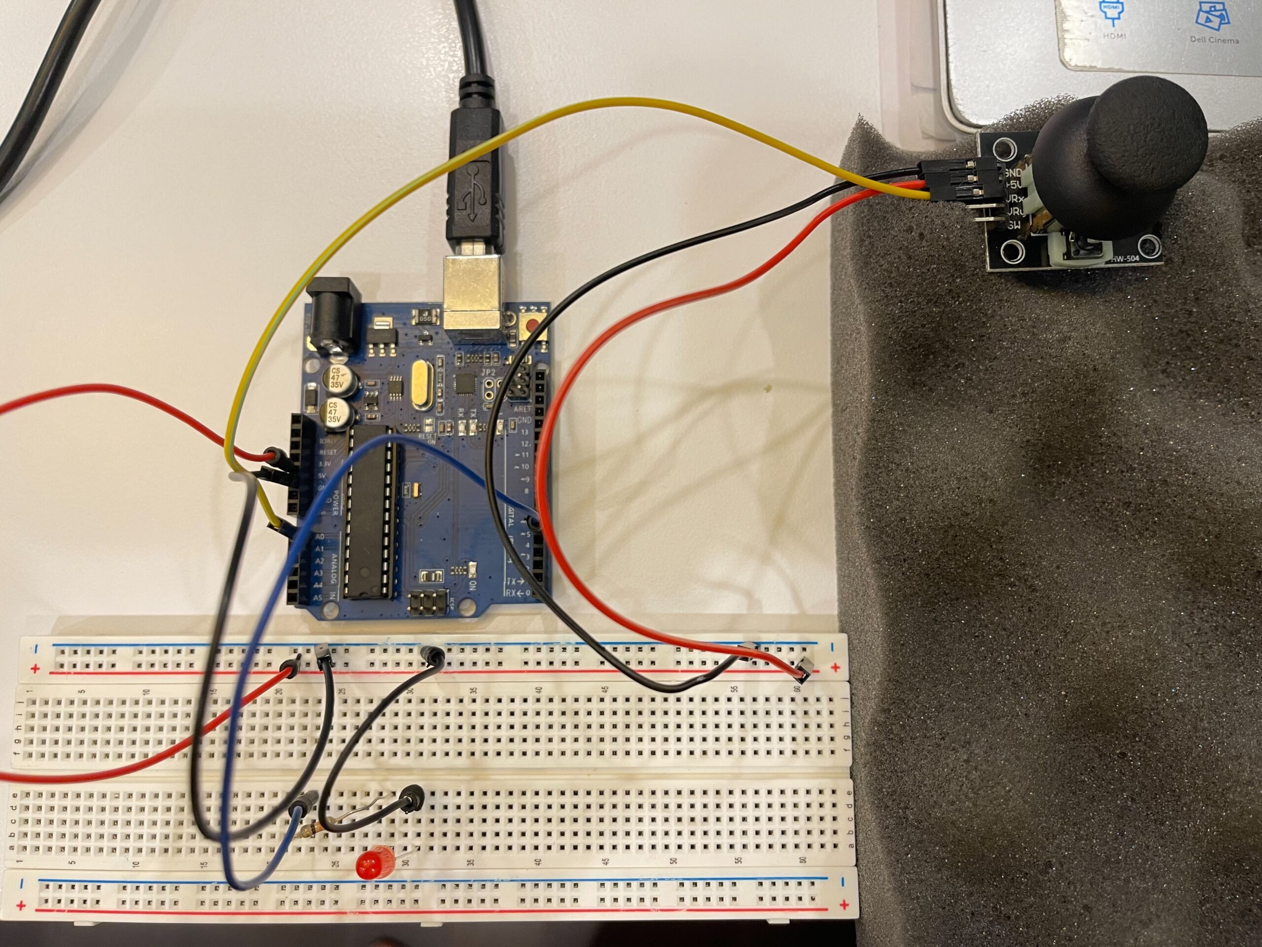
Circuit:
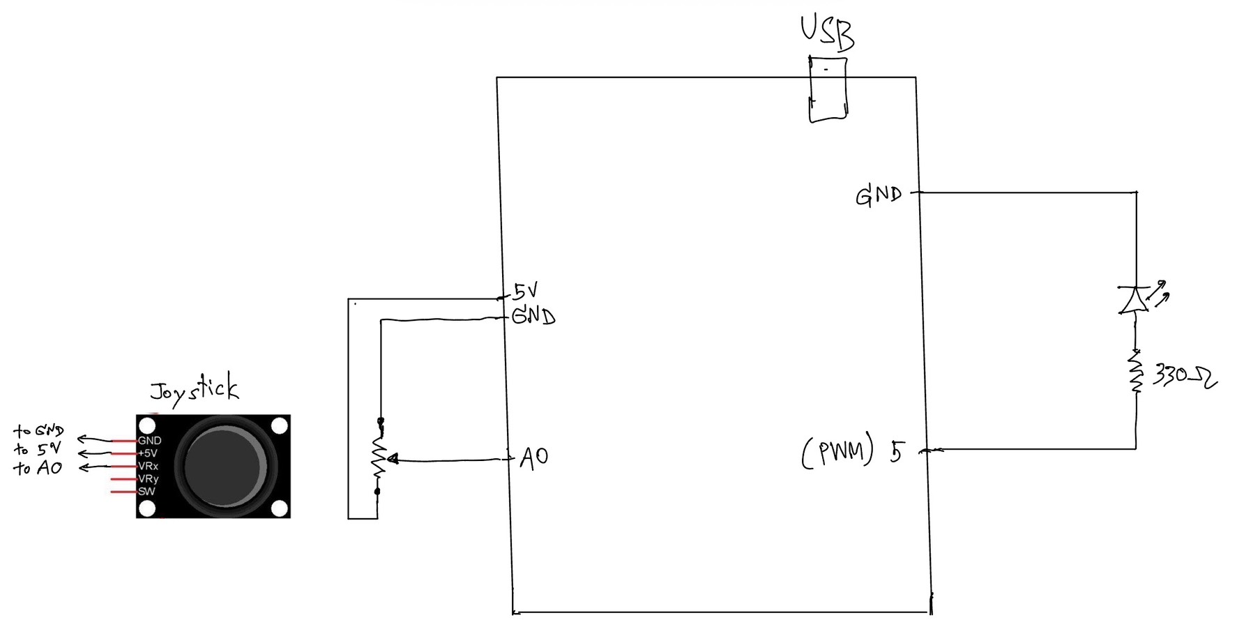
Hand Written Circuit:
In this exercise, we extended our work from the previous tasks by implementing bi-directional communication between Arduino and p5.js. The goal was to use an analog sensor to control the wind force in a physics simulation, and at the same time send data back from p5 to Arduino to control an LED.
We started from the gravity and wind example provided in class and kept the structure mostly unchanged. Instead of using keyboard input to control the wind direction, we replaced it with a joystick connected to Arduino. The horizontal axis of the joystick was read using analogRead() and sent to p5 through serial communication.
On the p5 side, the incoming value was read using port.readUntil(“\n”), then converted into an integer. We mapped this value to a range between -1 and 1, which was used as the horizontal wind force. As a result, moving the joystick left or right directly influenced the movement of the ball in the simulation.
To complete the bi-directional interaction, we added a simple condition in p5 to detect when the ball bounces on the ground. Whenever a bounce occurs, p5 sends a value back to Arduino. On the Arduino side, this value is read using Serial.parseInt(), and the LED is turned on or off accordingly.
This allowed us to create a system where Arduino sends sensor data to p5, and p5 responds by sending control signals back to Arduino.
⸻
What We Learned:
* How to implement bi-directional serial communication
* How to use an analog sensor (joystick) to control a physics simulation
* How to send control signals from p5 back to Arduino
* How physical and digital systems can interact in both directions
⸻
Code I’m Proud Of:
One part we are particularly satisfied with is how the system detects a meaningful bounce and avoids triggering unnecessary signals.
p5.js (bounce detection + sending data)
let bounced = 0;
  let floorY = height - mass / 2;

  // bottom bounce
  if (position.y > floorY) {
    position.y = floorY;

    if (velocity.y > 2) {
      velocity.y *= -0.9;
      bounced = 1;
    } else {
      velocity.y = 0;
    }
  }

  // send LED state back to Arduino
  if (port.opened()) {
    port.write(bounced + "\n");
  }
This section is important because it defines what counts as a “real” bounce. By using a velocity threshold, we ensure that only stronger impacts trigger the LED, while small movements at the ground are ignored.
⸻
Arduino (receiving and controlling LED)
int ledState = Serial.parseInt();

    if (Serial.read() == '\n') {
      digitalWrite(ledPin, ledState);
    }
This part connects the digital signal from p5 to a physical output. It shows how a simple value sent through serial communication can directly control hardware.
Challenges:
One issue we encountered was that the LED flickered rapidly when the ball reached the ground. Even though the ball appeared to be at rest, the system continued to detect small movements due to gravity and drag.
At first, this made the LED stay on or flicker continuously, which was not the intended behavior.
To solve this, we introduced a simple velocity threshold. Instead of triggering a bounce whenever the ball touched the ground, we only considered it a valid bounce when the downward velocity was greater than a certain value. After testing, we found that using a condition of velocity.y > 2 provided a stable and clear result.
This helped us better understand how physics simulations can produce small continuous movements, and why additional conditions are sometimes needed to define meaningful events.
⸻
Future Improvements:
If we were to continue developing this project, we would consider:
* Adding a dead zone to the joystick to reduce unwanted drift
* Using both axes of the joystick to control more complex motion
* Adding more LEDs or outputs to represent different events
* Improving the visual feedback to better match the physical response
Reference: