Conway’s Prism – Final Project Blogpost!!!

Concept:

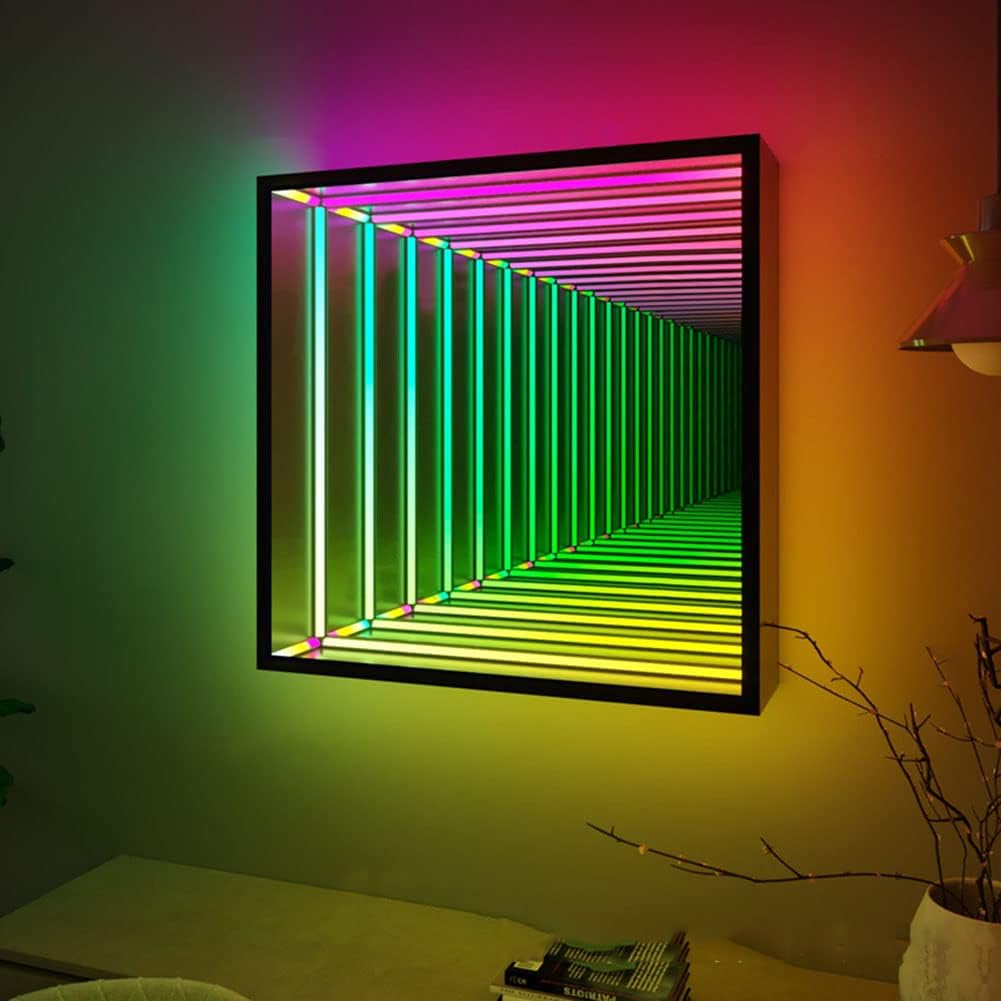
Infinity Mirror’s are a cool thing I came across while scouring the internet for inspiration for my final project, but I needed to add some sort of spice to it, and not just leave it with some rainbow hue that rotates in the mirror. That’s where Conway’s game of life comes in, each LED strip acts as a cell, and there’s nothing more perfect for it than a Conway’s game of life visualization.

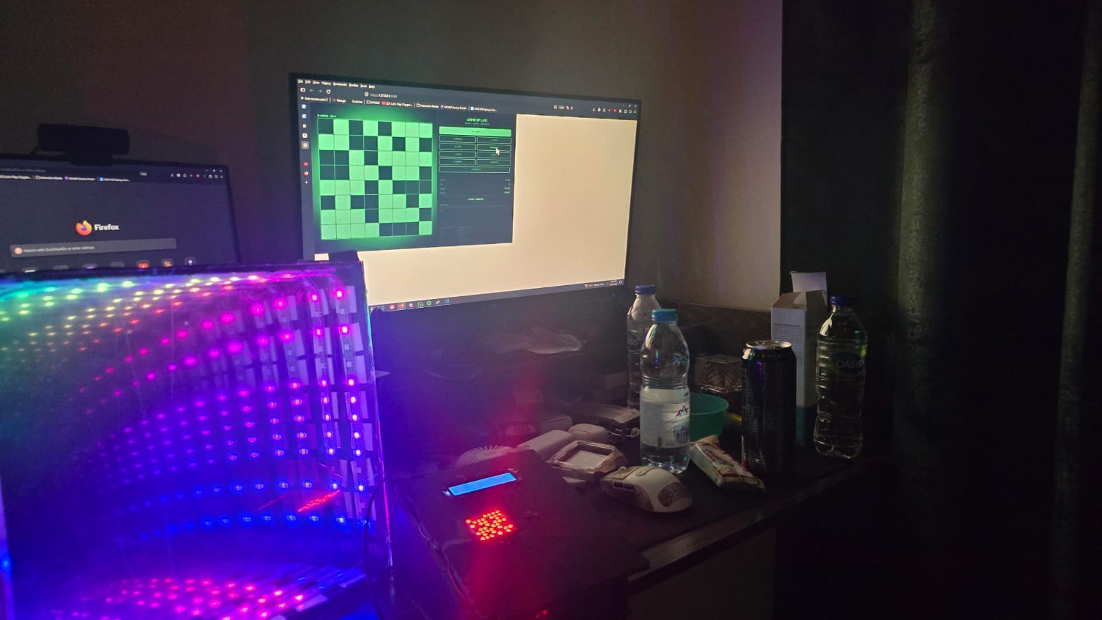
Demo:
Implementation:

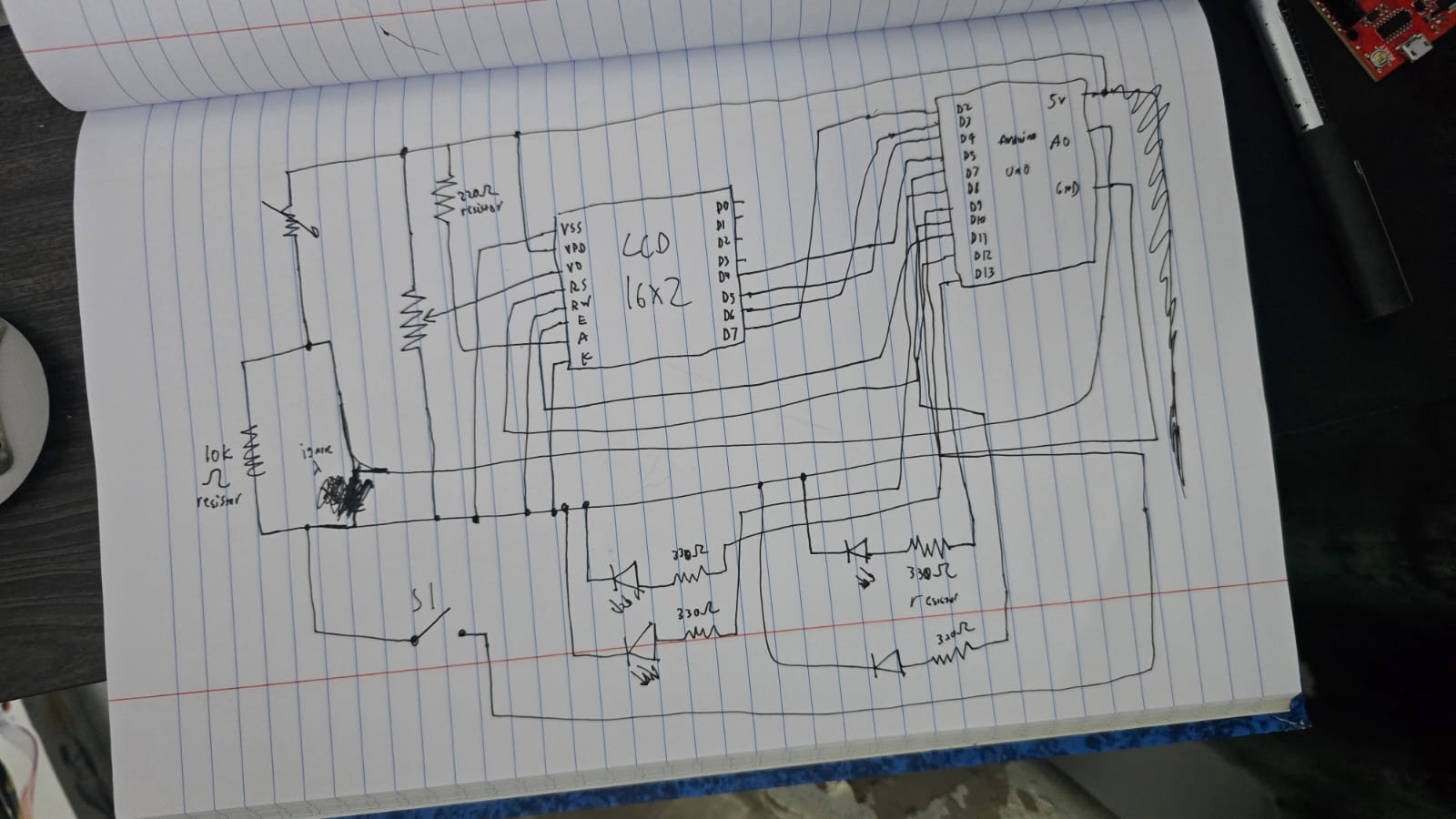
Sketch:

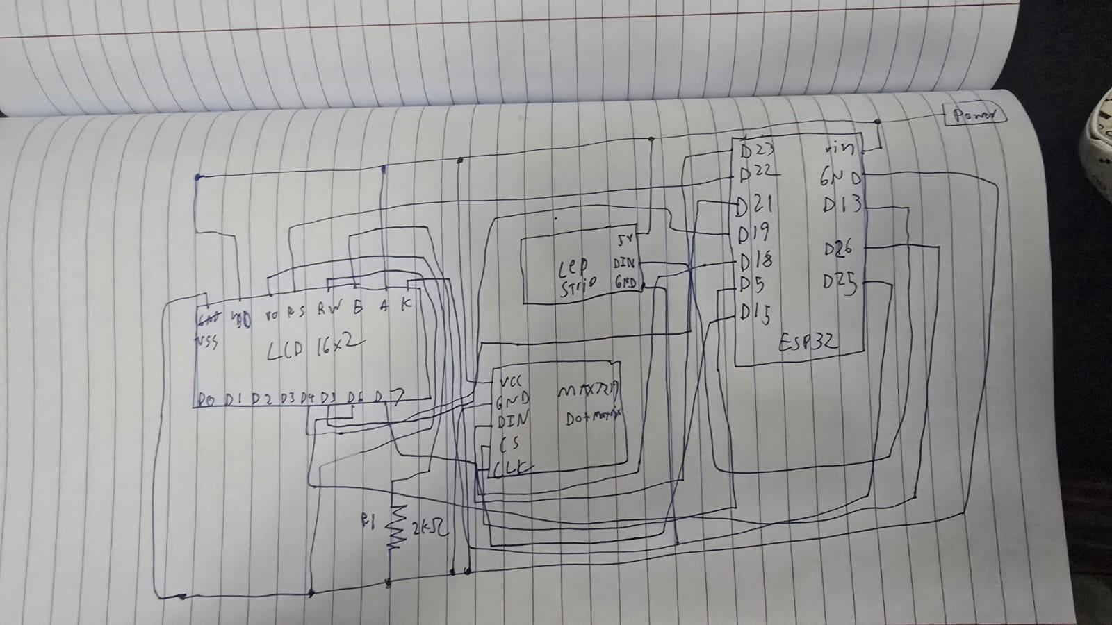
Schematic:
ESP32 Snippets:
WiFi.begin(SSID, PASSWORD);
while (WiFi.status() != WL_CONNECTED && tries < 30) {
    delay(500);
    tries++;
}
lcd.print(WiFi.localIP().toString());

The ESP32 connects to an exisiting Wi-Fi network and prints its assigned IP address on boot. The IP only needs to be read once and then hardcoded into sketch.js. The 30-attempt timeout prevents the firmware from hanging forever if credentials are wrong and returns and error message instead.

unsigned long lastLEDUpdate  = 0;
unsigned long lastLCDUpdate  = 0;
unsigned long lastMatrixBeat = 0;

if (now - lastLEDUpdate > 20)  { updateLEDs();   lastLEDUpdate = now; }
if (now - lastLCDUpdate > 500) { updateLCD();    lastLCDUpdate = now; }
if (now - lastMatrixBeat >


max(80, simSpeed / 4)) { updateMatrix(); lastMatrixBeat = now; }

There is 3 completely independant timers running concurrently with zero blocking. Each one records when it last fired and only acts again once enough time has elapsed. This is using the blink-without-delay pattern we learnt in class since delay would freeze the entire micro controller. With this approach the LEDs animate at 50fps, the LCD refreshes every 500ms, and the matrix beats at a rate derived from simulation speed.

if (now - lastMatrixBeat > max(80, simSpeed / 4)) {
    updateMatrix();
    lastMatrixBeat = now;
}

When paused, the matrix runs its own idle animation, a border with a pulsing center block. The rate of that animation is derived from simSpeed/4, meaning if you’ve set the simulation to run fast, the idle animation also pulses quickly. This makes the physical hardware feel responsive to your settings even when nothing is simulating. The max (80,…) floor prevents it from updating faster than ~12fps at maximum speed.

void onWSEvent(uint8_t num, WStype_t type, uint8_t* payload, size_t length) {
  switch (type) {
    case WStype_CONNECTED:
      wsServer.sendTXT(num, "HELLO:ESP32_READY");
      lcdFlash("p5.js Connected");
      matrixFlash();
      break;
    case WStype_DISCONNECTED:
      lcdFlash("Client Left    ");
      break;
    case WStype_TEXT:
      parseMessage(String((char*)payload));
      break;
  }
}

Websocket connections have lifecycle events. WStype_CONNECTED fires when p5.js first connects, and the ESP32 immediately sends a handshake back confirming its ready. WStype_DISCONNECTED fires if the browser closes or Wi-Fi drops, letting the hardware react gracefully rather than freezing on the last received frame. Only WStype_TEXT actually carries simulation data.

void parseMessage(String msg) {

  if (msg.startsWith("GRID:")) {
    int gridEnd  = msg.indexOf(',');
    String cells = msg.substring(5, gridEnd);

    int genStart = msg.indexOf("GEN:") + 4;
    int genEnd   = msg.indexOf(',', genStart);
    generation   = msg.substring(genStart, genEnd).toInt();

    int spStart = msg.indexOf("SPEED:") + 6;
    int spEnd   = msg.indexOf(',', spStart);
    simSpeed    = msg.substring(spStart, spEnd == -1 ? msg.length() : spEnd).toInt();

    int thStart = msg.indexOf("THEME:") + 6;
    if (thStart > 5) {
      themeIdx = constrain(msg.substring(thStart).toInt(), 0, 5);
    }

    // Decode the 64-char string into the grid array
    if (cells.length() == 64) {
      for (int r = 0; r < 8; r++)
        for (int c = 0; c < 8; c++)
          grid[c][r] = (cells[r * 8 + c] == '1') ? 1 : 0;
    }

    renderGridToLEDs();

  } else if (msg.startsWith("CMD:")) {
    String cmd = msg.substring(4);

    if (cmd == "PLAY") {
      simRunning = true;
      lcdFlash(">> RUNNING     ");
      matrixFlash();
    } else if (cmd == "PAUSE") {
      simRunning = false;
      lcdFlash("|| PAUSED      ");
    } else if (cmd.startsWith("SPEED:")) {
      simSpeed = cmd.substring(6).toInt();
    } else if (cmd.startsWith("THEME:")) {
      themeIdx = constrain(cmd.substring(6).toInt(), 0, 5);
    }
  }
}

This function is the backbone of the hardware side, it’s what parses the commands received from p5.js. The first part is “GRID: …”: This carries the full 64-character cell string plus metadata (generation step, or whenever the grid changes) The next part “CMD” is a lightweight command fired when a button is pressed in p5.js without a grid change, so pressing pause doesn’t redundantly re transmit all 64 cells. The ESP32 parses by prefix rather than a fixed schema, making it easy for me to extend with new commands later.

char genBuf[7];
sprintf(genBuf, "%06lu", generation % 1000000UL);
lcd.print(genBuf);
lcd.print(simRunning ? "  RUN" : "  PSE");

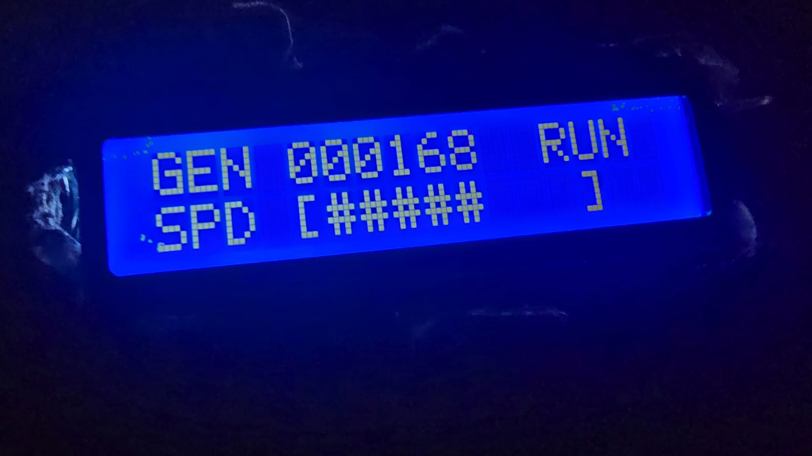
“%06lu” formats the generation count as exactly 6 zero-padded digits, so generation 42 displays as “000042” rather than shifting all the other text on the line (This fixes the issue where the LCD will keep past text if that specific position isn’t changed, so it will lead to a lot of gibberish if positions kept changing). The “% 1000000UL” wraps a tone million, preventing overflow on the display. For the speed part of the LCD, we print genBuf, which uses a map to convert the raw millisecond speed value into a visual bar of # characters (a progress bar).

if (simRunning) {
for (int r = 0; r < 8; r++)
for (int c = 0; c < 8; c++)
mx.setPoint(r, c, grid[c][r] == 1);
}

We take the grid we got from p5.js, and in the MAX7219 matrix, we simply turn on the point in that matrix wherever the grid is turned on to show the simulation on the dot matrix.

if (simRunning) {
    // mirror the actual grid
    for (int r = 0; r < 8; r++) { ... mx.setRow(0, r, rowByte); }
} else {
    // border + pulsing center block
    matrixFrame++;
    uint8_t f = matrixFrame % 16;
    mx.setRow(0, 0, 0xFF); mx.setRow(0, 7, 0xFF);
    if (f < 8) { mx.setPoint(3,3,true); mx.setPoint(3,4,true); ... }
}

When the simulation is paused the matrix doesn’t go blank, it switches to an idle animation: a solid border with a 2×2 block in the center that blinks at half the matrix update rate (f < 8 out of a 16 frame cycle). This makes it immediately obvious from the hardware alone whether the simulation is running or paused, without needing to read the LCD.

leds[i] = CHSV(baseHue + hue + (i * 6), 255, 255);
// dead cells:
leds[i] = CHSV(baseHue + hue + (i * 6), 200, 18);

Every LED gets a unique position in HSV colorspace, i*6 spreads 64 LEDs across 64×6 = 384 degrees of the color wheel, nearly a full rotation. As the global hue++ increments every 20ms the entire gradient rotates. baseHue shifts the starting color per-theme so each theme has its own dominant color family. Dead cells aren’t black, they get value:18, a very dim glow at the same hue, which inside an infinity mirror creates subtle depth between live and dead cells rather than a hard on/off contrast.


p5.js Snippets:
[grid, nextGrid] = [nextGrid, grid];

I took this optimization from my assignment 2 code, it has been a really long time so I will mention why this simple line really optimizes the algorithm by a lot. The GoL rules require all births and deaths to happen simultaneously, you can’t modify the grid you’re currently reading or updated cells corrupt neighbor counts of cells not yet processed. nextGrid is written during the step, then this single destructuring line swaps the two array references in O(1) with no copying. The old nextGrid becomes the write target for the next generation automatically.

let nc = (c + dc + COLS) % COLS;
let nr = (r + dr + ROWS) % ROWS;

Without wrapping, cells on the edge checking out-of-bounds neighbors return undefined, which correlates to 0 in arithmetic, silently giving border cells fewer neighbors than they should have. The “+ COLS” and “+ ROWS” before modulo is non-negotiable: in JavaScript -1 % 8 returns -1, not 7, so the addition ensures the value is always positive before wrapping. The top edge connects to the bottom, left to right, so the grid is a torus.

for (let [c, r] of born) {
    let px = GRID_X + c * CELL_SIZE + CELL_SIZE / 2;
    let py = GRID_Y + r * CELL_SIZE + CELL_SIZE / 2;
    for (let i = 0; i < 4; i++) particles.push(new Particle(px, py));
}

“born” is populated during “stepLife(),” only newly created cells (dead->alive) trigger particles, not cells that were already alive. Four particles spawn at the cell’s center pixel coordinates and fly outward. This gives the simulation visual feedback about where activity is happening, dense birth events create bursts of particles, stable still life produces nothing.

function sendStateToESP32() {
  let cells = "";
  for (let r = 0; r < ROWS; r++)
    for (let c = 0; c < COLS; c++)
      cells += grid[c][r];
  ws.send(`GRID:${cells},GEN:${generation},SPEED:${simSpeed},THEME:${themeIdx}`);
}

function sendCmd(cmd) {
  ws.send("CMD:" + cmd);
}

The grid is serialized as a flat 64-character string of 0 and 1s. A full state message looks like “GRID:0010011100…., GEN:42, SPEED:300, THEME:2.” Lightweight commands like “CMD:PAUSE” or “CMD:SPEED:180” skip the cell string entirely, pressing pause doesn’t re transmit the 64 characters redundantly. The ESP32 reads the prefix to know which parser to run.

let speedLabel = nf(map(simSpeed, 30, 900, 1, 0.03), 1, 2);
drawStat("SPEED", speedLabel + "x", ...);

Internally simSpeed is raw milliseconds between steps, easier to work with in timing logic. But displaying 300ms to a user is meaningless. map(0 convers the range 30-900ms to 1-0.03, so the UI shows a human-readable multiplayer like 0.50x or 1.00x. The inversion (low ms = higher multiplier) is intentional, fast simulation = high number feels intuitive.

function applyPreset() {
  initGrid();
  generation = 0;
  let key = presetKeys[presetIdx];
  if (key === "RANDOM") {
    for (let c = 0; c < COLS; c++)
      for (let r = 0; r < ROWS; r++)
        grid[c][r] = random() > 0.55 ? 1 : 0;
  } else {
    let pts = PRESETS[key];
    for (let [c, r] of pts) {
      if (c < COLS && r < ROWS) grid[c][r] = 1;
    }
  }
}

Each preset is stored as absolute [col, row] coordinates rather than offsets, sized to fit the 8xx grid. The “if (c < COLS && r < ROWS) guard means a badly defined preset can never write out of bounds and corrupt memory. RANDOM gets its own branch, each cell independently has a 45% chance of being alive. That specific threshold was tuned: lower than ~35% and the grid dies out almost immediately, higher than ~55% and it suffocates just as fast. 45% tends to produce a chaotic but sustainable starting population.

Proud moments:

Honestly I did not originally like this idea, it was like 3 am and I just wanted to put an idea and go to sleep. However it turned out so much better than I expected and I ended up really liking with what I came up with. Finishing the mirror and turning it on for the first time to see the effect actually working made me really happy and proud of myself, as well as running the code for the first time with p5js to see everything working just how I intended and look even better than I expected. Overall I am really happy and proud of this project.

Future improvement:

– Sound reactivity: I was considering using my microphone module on the ESP32 to inject new live cells in sync with audio, but I did not know if I had time.

– Saved patterns: Letting users save their favorite starting configurations to flash memory so they persist between sessions would be a really nice addition.

– HUD Tutorial: A real-time tutorial over the HUD would be a nice addition to get new users started with how a simulation works and how my simulation works.

– Population graph: I originally wanted to add an LED strip that would show the current population with different colors (green, yellow, red) but I did not have an LED strip connector, and my DIY attempts and connecting the wires to the copper pads did not work out successfully sadly.

Links:

github.com/Links2004/arduinoWebSockets

docs.espressif.com/projects/arduino-esp32/en/latest/api/wifi.html

https://developer.mozilla.org/en-US/docs/Web/API/WebSocket
GitHub Link


Conway’s Prism – User Testing

Brother 1 User Testing:

Explained info: Rules of con way’s game of life

Project Walk Through:

Bonus – 9 year old brother test subject:

Conclusion:

From my first brother, he didn’t really know how to navigate the website, and I think this is due to the lack of knowledge of how simulations work in general, and I only briefly explained what Conway’s game of life is to him. To be more nitpicking, the paused and running text on the top left of the grid doesn’t seem to be very noticeable by both siblings and I had to tell them both the simulation was paused when they were just clicking the grid hoping to start something. The rest of the buttons aren’t really used either unless I explicitly tell them about it, maybe one part is just them not knowing what to do at all for the video. But what I think the core issue is the fact most people aren’t familiar with how simulations work.

The experience itself works pretty well, it does its purpose in showing something cool entirely made by the user, I however wish I was able to add more external controls, but my potentiometer pins broke while I was trying to add that and the joystick module just would not fit with my design, so I had to resort to controlling the simulation through p5js (I did add some keyboard shortcuts).

For how to solve the issue of the lack of knowledge, I think If I had time I would add some tutorial overlay when the website is first loaded in, so like when you first launch you get a short brief explanation of what every button does in a speech bubble style, have the user do what the tutorial is asking them to do before moving on to get them familiar with the controls. I should also make the pause/running indication more visible, maybe by changing the grid outlines or the background from red -> green or something along the lines, something more “obvious.” A big fat “PAUSED” in the middle of the grid could work too!

The buttons aren’t really intuitive for anyone who isn’t aware of simulations in general, fast, slow, random, clear, presets all were buttons ignored unless I explicitly mentioned, so this should also be fixed with my how to use overlay tutorial type of thing. However the process of clicking on the grid and seeing stuff react when the simulation started seemed to make them understand the mapping pretty instantly! So I think I would call this project a success, just simply lacking some intuitive upgrades to the UI.

Final Project Concept – Conway’s Prism

My concept:

I want to do a visualization of Conway’s game of life in real life, but I didn’t want it to be something boring or just simple, so after a long while of searching for inspiration, I landed on infinity mirrors.

The way these work is that there is LED lights sandwiched between 2 mirrors, the back mirror is fully reflective, and the front mirror is a two-way mirror, where its partially reflective and partially transparent. The way it creates this illusion with a single line of LED is:

– LED’s inside emit light.
– Some light goes straight out through the front
– Some light reflects off the back mirror
– The reflected light hits the front mirror again, part of it escapes to your eyes and part of it reflects back inside
– This keeps bouncing back and forth

Each bounce loses a bit of intensity, so you see a chain of dimmer and dimmer reflections that look like they’re going deep into the mirror.

So the main idea is the simulation of the game of life, however the user can decide which cells to start with, or make it random, or add new cells while the simulation is running.

Arduino:

The Arduino is going to be controlling which LED lights turn on, I bought WS2812B LED strip lights which allows me to control each led in a strip individually. I might add a potentiometer and buttons for reset or changing the light brightness or speed of simulation, however I will decide on this depending on how building the project goes.

P5:

This will handle the simulation aspect of it, it will calculate what cells live or die in the next generation and sends these updates to the Arduino so it turns on or off the respective LED’s, if I can’t manage to have an external control panel, then my backup plan will just be having the panel be done in p5js with a UI a user can control.

Progress:

I used the stipend to buy the resources needed for this project which are:

– Black foam boards for the base: https://www.amazon.ae/dp/B0D3Y656M2?ref=ppx_yo2ov_dt_b_fed_asin_title

– 5 Meter WS2812B LED strips: https://www.amazon.ae/dp/B0D1Y995V6?ref=ppx_yo2ov_dt_b_fed_asin_title

– Reflective mirror stickers: https://www.amazon.ae/dp/B0FY2GBZ2S?ref=ppx_yo2ov_dt_b_fed_asin_title

– Clear acrylic sheet: https://www.amazon.ae/dp/B0CK4XFZ8D?ref=ppx_yo2ov_dt_b_fed_asin_title

– One way privacy film: https://www.amazon.ae/dp/B0GCYXYK5L?ref=ppx_yo2ov_dt_b_fed_asin_title

Week 11 – Final Project

For the final project, I was thinking of mixing in one of my old p5 assignments, assignment 2 if I remember correctly, the one with conway’s game of life, now, I want to make an infinity mirror, but what you see inside is the process of conway’s game of life instead of standard colors, with some buttons or some external stuff to change how the cells behave and add some variety.

This will require me to buy a picture frame, for the frame and the acrylic, and also get a one way window film to attach to create that infinity mirror effect, along with buying LED lights also. I plan on adding a lot of interactivity with the user to change how the cells live and die so its less of just a show and more of something interactive. The p5js will handle the processing of the game of life, and maybe provide a UI to handle it or I might pivot towards using hands with ml5js. The Arduino will take the data from p5js and turn on the led’s when they need to be turned on.

Week 11 – Creative Reading

This reading shifted my understanding of accessible design by challenging my assumption that discretion is the ultimate goal when designing for disabilities. Previously, I always believed that successful medical devices were those that blended in, much like the “pink plastic” hearing aids the author talks about. However, the text highlights how prioritizing invisibility subtly reinforces a culture of shame. Understandably so, a lot of the texts I read during my first year writing seminar talked about how invisibility can be used to have power over certain groups of people or take away power from such groups, although not exactly the same, the negative connotation is there even with disability. I was particularly struck by the discussion of Aimee Mullin’s intricately carved wooden prosthetic legs. It led me to the realization that when designers move beyond mere clinical problem-solving, they allow users to project a bold, positive image. By treating prostheses as a canvas for self-expression rather than deficit to conceal, design becomes an empowering tool.

A pretty popular design I can think of that follows the author principles is Nike’s FlyEase sneaker line. It was originally engineered to help people with mobility disabilities put on shoes hand-free. Because the design is sleek and fashionable, it became a mainstream success desired by the public. It makes me wonder, if fashion and visibility are so crucial to de-stigmatizing disability, how do we convince competitive consumer markets to prioritize aesthetic investment in specialized products without commodifying the disability itself?

Week 11 Assignment

Exercise 1:

Demo:

Schematic:

Implementation:

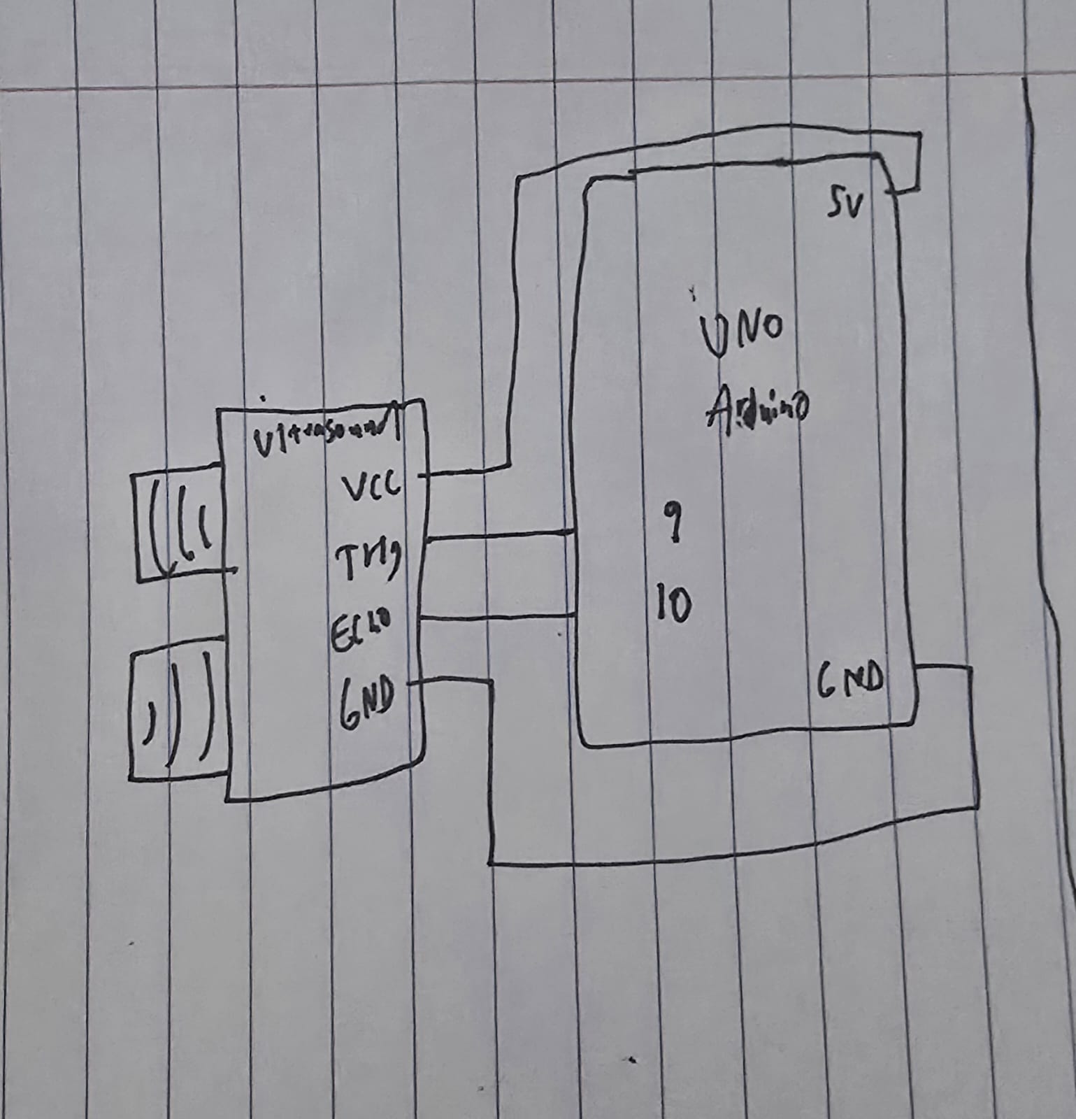
I used an ultrasound sensor for this exercise, so the ellipse moves depending on how close or far my hand is from the sensor.

void loop() {
  // Trigger the sensor
  digitalWrite(trigPin, LOW);
  delayMicroseconds(2);
  digitalWrite(trigPin, HIGH);
  delayMicroseconds(10);
  digitalWrite(trigPin, LOW);

  // Measure the bounce back time
  long duration = pulseIn(echoPin, HIGH);
  
  // Calculate distance
  int distance = duration * 0.034 / 2;

  // Send just the number to p5.js
  Serial.println(distance); 

  delay(50);
}

The code for using the sensor is pretty standard, trigger it so often, measure the duration using the formula (speed * time), and then send that to p5js.

Speed is the speed of sound (0.034 cm per microsecond) and time is duration / 2 since it is a round trip.

// Read from serial
    let str = port.readUntil("\n");
    if (str.length > 0) {
      let val = int(str);
      // Validate value
      if (!isNaN(val)) {
        sensorValue = val;
      }
    }


    // Map the value
    let xPos = map(sensorValue, 5, 50, 0, width);
    // Constrain the ellipse to canvas
    xPos = constrain(xPos, 0, width);

    fill(0, 255, 200);
    noStroke();
    ellipse(xPos, height / 2, 50, 50);

From p5js side, we take the value, validate it, then create a mapping of the value to x position as well as constraining it, then finally draw the ellipse.

Exercise 2:

Demo:

Schematic:

Implementation:

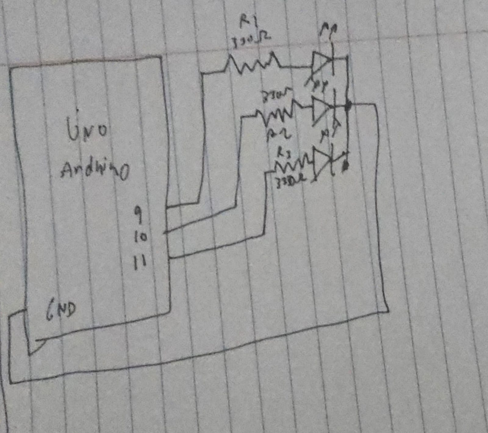
In p5js, I have 3 sliders, 1 for R, 1 for G, and 1 for B, I am using an RGB LED, so we can switch around the sliders to get our custom color from the LED.

// Read the three integers sent from p5.js
// parseInt() looks for digits and skips non-digits
int r = Serial.parseInt();
int g = Serial.parseInt();
int b = Serial.parseInt();

// Look for the newline character to confirm the end of the message
if (Serial.read() == '\n') {
  // Apply the brightness to each pin
  analogWrite(redPin, r);
  analogWrite(greenPin, g);
  analogWrite(bluePin, b);

On the Arduino side the code is pretty simple, just read each color and write it to the LED.

// Send to Arduino
port.write(r + "," + g + "," + b + "\n");

This is really what’s doing the work, it takes the values from the slider and sends them to the Arduino in such a format that it could read it easily.

Exercise 3:

Demo:

Schematic:

Implementation:

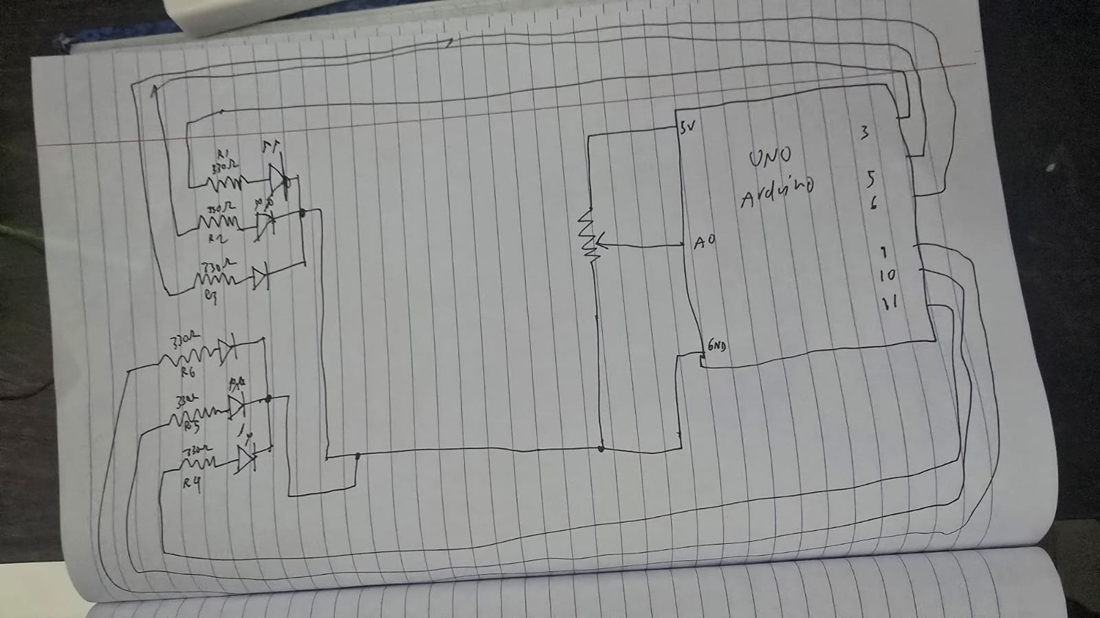
I copied the basic implementation of the wind mechanics from the code, however instead of left and right buttons, I switched out with a potentiometer:

let windForce = map(sensorValue, 0, 1023, -0.5, 0.5);

I have 2 RGB LED’s, and each light up depending on what side of the “wall” the ball hits.

// Left Wall
if (position.x < mass/2) {
velocity.x *= -0.9;
position.x = mass/2;
sendColor("L");
}
// Right Wall
if (position.x > width - mass/2) {
velocity.x *= -0.9;
position.x = width - mass/2;
sendColor("R");
}

The code to send the colors itself to the Arduino is:

// Sending color + direction
function sendColor(side) {
  if (port.opened()) {
    let r = floor(random(255));
    let g = floor(random(255));
    let b = floor(random(255));
    // Sending: Side,R,G,B (e.g., "L,255,0,0")
    port.write(side + "," + r + "," + g + "," + b + "\n");
  }
}

We create a random number for each color and then send it to the Arduino along with the direction.

if (side == 'L' || side == 'R') {
  Serial.read(); // Skip the comma
  int r = Serial.parseInt();
  int g = Serial.parseInt();
  int b = Serial.parseInt();

  if (side == 'L') {
    flash(L_red, L_green, L_blue, r, g, b);
  } else {
    flash(R_red, R_green, R_blue, r, g, b);
  }
}

From the Arduino side, we read the colors like how we read it in exercise 2, then depending on the side we light up the left or right side.

P5js code

GitHub Code

Week 10 – Creative Reading

“Vision of the Future” videos have been a thing since the early 21st century, the amazing hologram screen, or people waving their hands in the air to move digital windows around (I mean we have augmented reality for that now). It looks futuristic, sophisticated and innovative, but from an interaction perspective, it is actually incredibly timid.

I agree with what Bret is saying, a tool is supposed to amplify human capabilities, converting what we can do into what we want to do, and if that entire principle is gone, then it isn’t just not a good tool, it is not a tool at all.

Most modern devices ignore the two things hands do best, feeling and manipulating, so how can we call these ideas revolutionary if its going backwards?

Bret’s point about “finger-blindness” is actually terrifying to think about, what we do for granted the future generation may struggle with. If we do not use our hands to feel texture, weight, and pliability, we lose the ability to understand the “inner meaning” of objects. We are building a world where we can spend our entire lives immobile, starting at a “hokey visual facade” that has no physical connection to the work we are doing.

If the future of interaction does not let us see, feel, and manipulate space simultaneously, then it is not a future worth building or investing it.

Week 10 – Piano

Demo Below:


Concept:

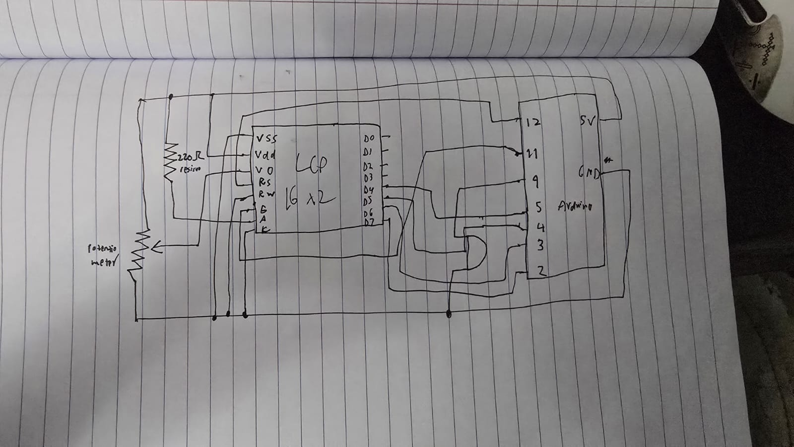
We came up with a piano that utilizes your keyboard presses and a buzzer, using keys from A-L allows you to play 9 different notes. We added an LCD that displays the note of each key and the frequency of that note.

Implementation:

Schematic:

The components used are pretty simple, just being an LCD device and a buzzer. We wrote 2 files of code for this, a python file and an c++ file. As typing the letter into the serial monitor every time you wanted to play a note would be counter-intuitive, we wrote a python file that listens to your key presses, and if you press a key between A and L, then it will send that key press to the arduino which ends playing the note that correlates to that key press.

try:
    arduino = serial.Serial('COM11', 9600, timeout=1)
    ...
except:
    ...

while True:
    if keyboard.is_pressed('a'):
        arduino.write(b'A')
        time.sleep(0.15) 
    elif keyboard.is_pressed('s'):
        arduino.write(b'S')
        time.sleep(0.15)
    elif keyboard.is_pressed('d'):
        arduino.write(b'D')
        time.sleep(0.15)
    elif keyboard.is_pressed('f'):
        arduino.write(b'F')
        time.sleep(0.15)
    elif keyboard.is_pressed('g'): 
        arduino.write(b'G')
        time.sleep(0.15)
    elif keyboard.is_pressed('h'):
        arduino.write(b'H')
        time.sleep(0.15)
    elif keyboard.is_pressed('j'):
        arduino.write(b'J')
        time.sleep(0.15)
    elif keyboard.is_pressed('k'):
        arduino.write(b'K')
        time.sleep(0.15)
    elif keyboard.is_pressed('l'):
        arduino.write(b'L')
        time.sleep(0.15)

    if keyboard.is_pressed('esc'):
        print("Closing...")
        break

arduino.close()

Here we first try to connect to the arduino using the port and the buad rate that is on the arduino IDE, then until the program stops, we check for any key presses, and if it matches one of our conditional statements, we write that letter to the arduino.

switch (key) {
  case 'A': frequency = 262; noteName = "C4"; break;
  case 'S': frequency = 294; noteName = "D4"; break;
  case 'D': frequency = 330; noteName = "E4"; break;
  case 'F': frequency = 349; noteName = "F4"; break;
  case 'G': frequency = 392; noteName = "G4"; break;
  case 'H': frequency = 440; noteName = "A4"; break;
  case 'J': frequency = 494; noteName = "B4"; break;
  case 'K': frequency = 523; noteName = "C5"; break;
  case 'L': frequency = 587; noteName = "D5"; break;
  default: return; // Ignore any other keys
}

Here we have a switch statement which checks whether we got a matching letter, which then returns the respective frequency and note. We got these frequencies for each note from here: https://en.wikipedia.org/wiki/Piano_key_frequencies as we wanted it to sound as similar as possible to a piano. The LCD shows the note you play and the frequency of that note when you play it. A potentiometer is used to control the contrast of the LCD!

GitHub Link!

Reflection:

Currently this is a single press piano meaning you can’t play multiple multiple notes at once, so an improvement that can be made is to find some way to be able to play multiple notes at once, otherwise this works perfectly, and is simple and accessible to anyone!

Week 9 – Light Show Charging

Demo Below:

Concept:

The idea of this is that, you “charge” up a light show by shining a really bright light on the photo resistor, once you charged it up for a good 10 seconds, a light show happens! A yellow RGB light slowly brightens up as the percentages reaches to a 100 while charging. I implemented a physical button that resets everything to stop the light show and so that you are able to charge it again.

Implementation:

Schematic:

The components used are RGB lights, a photo resistor, a 2×16 LCD and a potentiometer.

#include <LiquidCrystal.h>

// RS, E, D4, D5, D6, D7
LiquidCrystal lcd(12, 11, 5, 4, 3, 2);

const int ldrPin = A0;
const int btnPin = 7;     // Button
const int ledAnalog = 9;  // The fading LED
const int ledA = 13;      // Light show LED
const int ledB = 10;      // Light show LED
const int ledC = 8;       // Light show LED

int threshold = 600;
unsigned long startMs = 0;
bool charging = false;
bool done = false;

Here we initialize everything, since LCD has its own module and example code, I took the initialization and syntax from there, we assign pins, the threshold and set everything to false since the program just began.

// Reset logic
  if (digitalRead(btnPin) == LOW) {
    // Set variables to original values
    startMs = 0;
    charging = false;
    done = false;
    // Turn off everything
    digitalWrite(ledA, LOW);
    digitalWrite(ledB, LOW);
    digitalWrite(ledC, LOW);
    analogWrite(ledAnalog, 0);
    lcd.clear();
    lcd.print("System Reset");
    delay(500);
  }

This is the reset code for when the button is pressed, it just turns off everything, and sets charging and done false to enter the mode it originally started with and just reset everything to the origin.

if (!done) {
    // When light above threshold start counting
    if (light > threshold) {
      if (!charging) {
        startMs = millis();
        charging = true;
      } ...
  }
}

We have nested if statements here, to first check if the charging is done, if it isn’t we check if the light crosses the threshold, and if we aren’t already charging, we should start. If the light passes down the threshold, the charge goes to 0 and we restart.

  // Light show time
  lcd.setCursor(0, 0);
  lcd.print("FULLY CHARGED!  ");
  lcd.setCursor(0, 1);
  lcd.print("   100 PERCENT  ");
  
  // Blink Pattern
  digitalWrite(ledA, HIGH); delay(100);
  digitalWrite(ledB, HIGH); delay(100);
  digitalWrite(ledC, HIGH); delay(100);
  digitalWrite(ledA, LOW);  digitalWrite(ledB, LOW); digitalWrite(ledC, LOW);
  delay(100);
}

When it has charged for 10 seconds or more, we set done to true, which calls the else commands and starts the light show till stopped by the button or simply turned off.

Code here:
GitHub link

Reflection:

Some ways I thought of improving this is having a proper choreography of the lights that go along with some music, maybe manually do it or write up an algorithm that works for any song, either way I think that would improve this project. It was fun learning about the LCD however, and I am glad that I am able to use it now.

Week 9 – Readings Responses

Reflection 1: On “Physical Computing’s Greatest Hits (and Misses)”

This reading really challenged how I think about originality in my projects. It is easy to feel discouraged when you realize a project you are excited about has already been done thousands of times. This is something I have experienced in my past assignments too, where it often felt like I was just making a copy of something else. However, as Tigoe points out, these classics are repeated because they tap into fundamental human expressions like movement and gesture.

This made me rethink my own approach to class projects. I realized that a project does not have to be a world-first to be successful. The value lies in the twist you add, how you refine the design, change the interaction, or make it feel unique to your own creative voice. I feel like this is something we all do unintentionally because we each have different styles and tastes.

Reflection 2: Making Interactive Art

The second reading shifted my perspective on the role of the designer in interactive art. I used to think that as a creator, I needed to explain exactly what my project was supposed to do so that people would not get confused. However, Tigoe suggests the opposite: build the environment, provide the context, and then shut up.

The idea that the audience completes the work through their own actions is powerful, but I think it is situational. Some projects are meant to do exactly what the creator intended, and there is not really anything else for the user to add. While I agree with Tigoe’s take for certain artistic pieces, I do not think it is universally true for every single project. Sometimes a clear, guided experience is exactly what is needed.