Week 14: Persian Rug Design

For my final project, I created an interactive textile pattern generator called Persian Rug Machine. The project lets the user create decorative rug-like compositions using a custom Arduino controller connected to p5.js. Instead of drawing directly on the screen, the user changes the design through six physical arcade buttons. I wanted the project to feel like a small textile machine where the user can build a visual composition through touch.


Github link
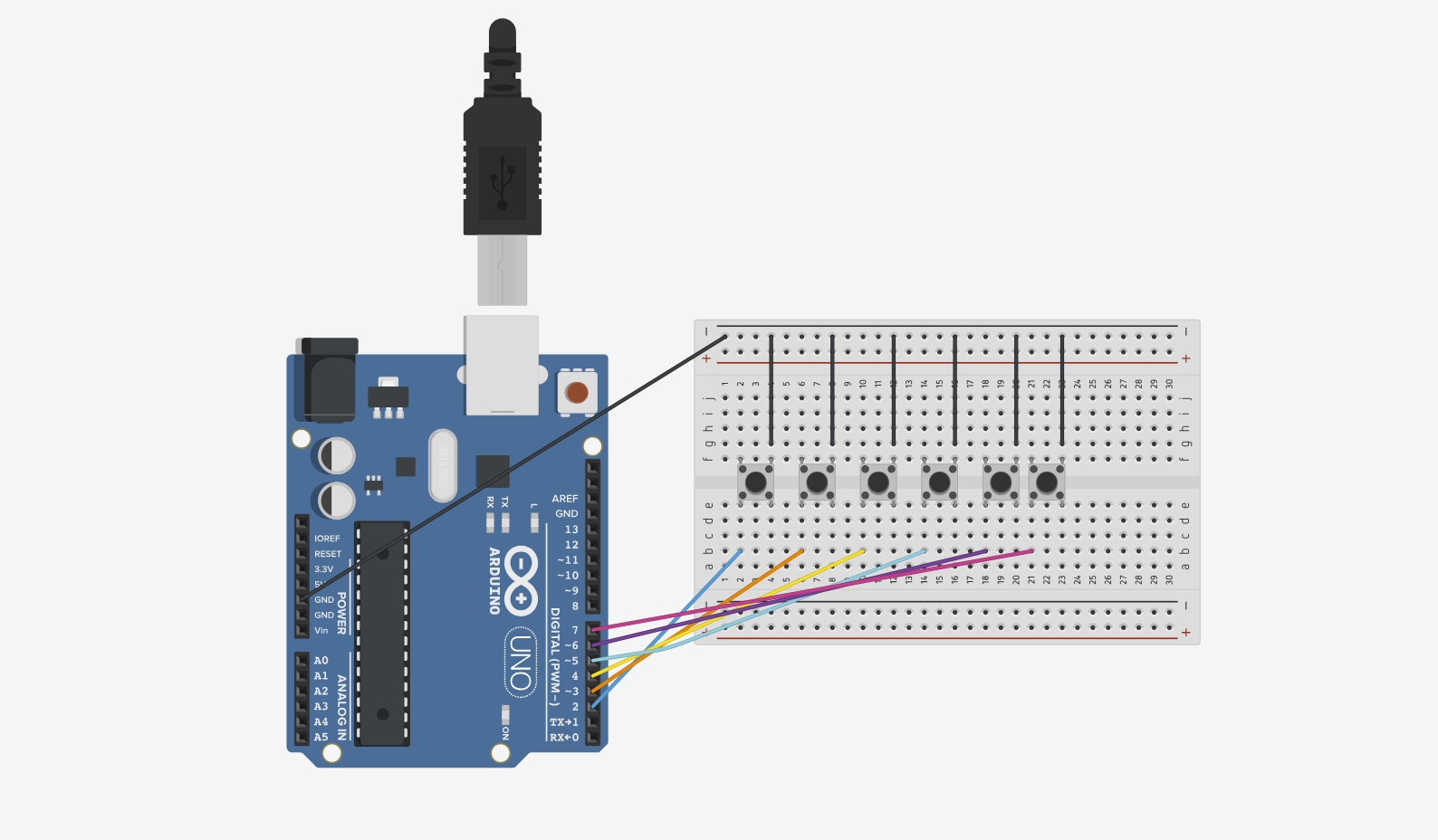
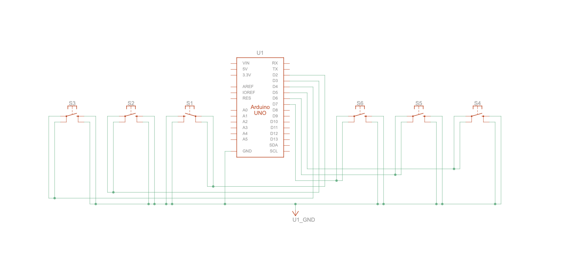
game demoTinkercad schematic
The project changed a lot while I was developing it. I first planned to use buttons, potentiometers, and a joystick. I also tested a fighting stick controller, but I eventually returned to Arduino because it matched the assignment better and made the physical communication with p5.js more central. I also decided not to use the joystick because the rug looked stronger when the center medallion stayed centered. Simplifying the controller made the interaction clearer and more intentional.

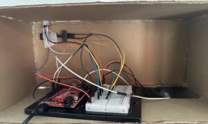
The final controller uses six buttons. Each button sends a command from Arduino to p5.js through serial communication. The buttons control motif shape, color palette, background color, line style, center medallion style, and finish/save. This gave the user enough creative control without making the interface too confusing.

The visual inspiration came from Persian rugs, embroidery, floral textile motifs, geometric ornament, and tiled decorative systems. I focused on repetition, symmetry, borders, central medallions, and controlled color palettes so the patterns would feel intentional instead of random. I wanted the final compositions to feel decorative and textile-like, not just like shapes moving on a screen.

The Arduino side reads the buttons using Input_Pullup. When a button is pressed, Arduino sends a text command such as “motif”, “palette”, or “finish” to p5.js. Then p5 reads the command and changes the rug design.

if (command === "motif") {
  patternMode = (patternMode + 1) % 3;
}

if (command === "background") {
  bgColorIndex = (bgColorIndex + 1) % bgColors.length;
}

if (command === "finish") {
  state = "final";
  setTimeout(() => {
    saveCanvas("DIY-Persian-rug", "png");
  }, 300);
}

One part of the code I am proud of is the repeated motif system. I used nested loops to place motifs across the screen in a structured grid, which helped the rug feel more like a textile composition.

for (let i = 0; i <= cols; i++) {
  for (let j = 0; j <= rows; j++) {

I also used distance from the center medallion to scale the motifs, which made the composition feel more layered and less flat.

let d = dist(x, y, centerX, centerY);
let s = map(d, 0, width * 0.7, tileSize, tileSize * 0.45);

I separated the motifs into different functions, such as drawDiamondMotif(), drawFloralMotif(), and drawStarMotif(). This made the code easier to organize and allowed the user to switch between motif styles in real time. I also included borders, straight lines, and zigzag lines to make the composition feel closer to woven or embroidered designs.

I added oud background music using p5.sound and a custom font to make the project feel more complete. I also removed the bottom instruction panel from the studio screen because the physical buttons are already labeled, so the screen can focus more on the rug itself.

The biggest challenge was balancing creative freedom with visual cohesion. At first, adding too many controls made the results feel chaotic. Simplifying the controller to six clear buttons made the project easier to use and made the final rug designs feel more intentional. Another challenge was making the Arduino-to-p5 communication clear, so I used labeled text commands instead of only sending numbers.

Overall, I am proud of how the project became a small custom textile machine. The user physically presses buttons to shape the rug, and the final button presents and saves the completed design. I like that the final version connects the physical controller and the digital pattern in a clear and direct way.

references:

Pinterest inspiration:

https://pin.it/T0fnQGXuC

https://pin.it/4DNaWlxmq

https://pin.it/1tYDm2dmi

https://pin.it/4xp7tjsH0

https://pin.it/30hUjJpG9

Week 13: Final project and User testing

For my final project, I focused on user testing. At that stage, my original Arduino circuit was not working properly, and the joystick I had first planned to use also did not work as intended. Because of that, I carried out the user testing using the fighting stick controller together with p5 through the Gamepad API. This meant that the testing phase focused mainly on the p5 interaction and the overall mapping of the controls, instead of the final Arduino-to-p5 system I had originally planned.

Even though I still wanted the final version of the project to include an Arduino component, the fighting stick allowed me to continue testing the interaction design and visual system instead of stopping the project completely. The main goal of the testing was to see whether users could understand how the controls changed the rug composition, whether the mapping felt clear, and whether the overall experience felt exploratory and engaging without needing much explanation.

user testing video

Overall, the p5 side of the project was working well during testing. My sister was able to press different controls and see clear visual changes in the textile composition. She could tell that different controls were changing things like the motif, palette, and other visual properties. The strongest part of the interaction was that the visual response happened immediately, so she understood that her input was directly affecting the rug design.

The main issue was not with the visual response itself, but with the text at the bottom of the screen. I had included button hints there to explain which control was mapped to what action, but that part was not working clearly enough. Because of that, my sister had to guess which button did what before she fully understood the system. Once she started experimenting, she was able to figure it out, but the labels and hint text were not as clear or reliable as they should have been for a first-time user.

This testing helped me understand that the p5 interaction and visual system were already strong enough to support the project, since my sister could still explore and generate designs successfully. It also showed me clearly which part needed more work, which was fixing the control mapping and the guidance text on screen. After the testing, I continued developing the project by fixing the interaction and working on a version that included Arduino, since the fighting stick was helpful as a temporary workaround for testing, but it was not the final interaction system I wanted for the project.

References:

https://developer.mozilla.org/en-US/docs/Web/API/Gamepad

https://developer.mozilla.org/en-US/docs/Web/API/Gamepad_API/Using_the_Gamepad_API


Final Project Post

Concept

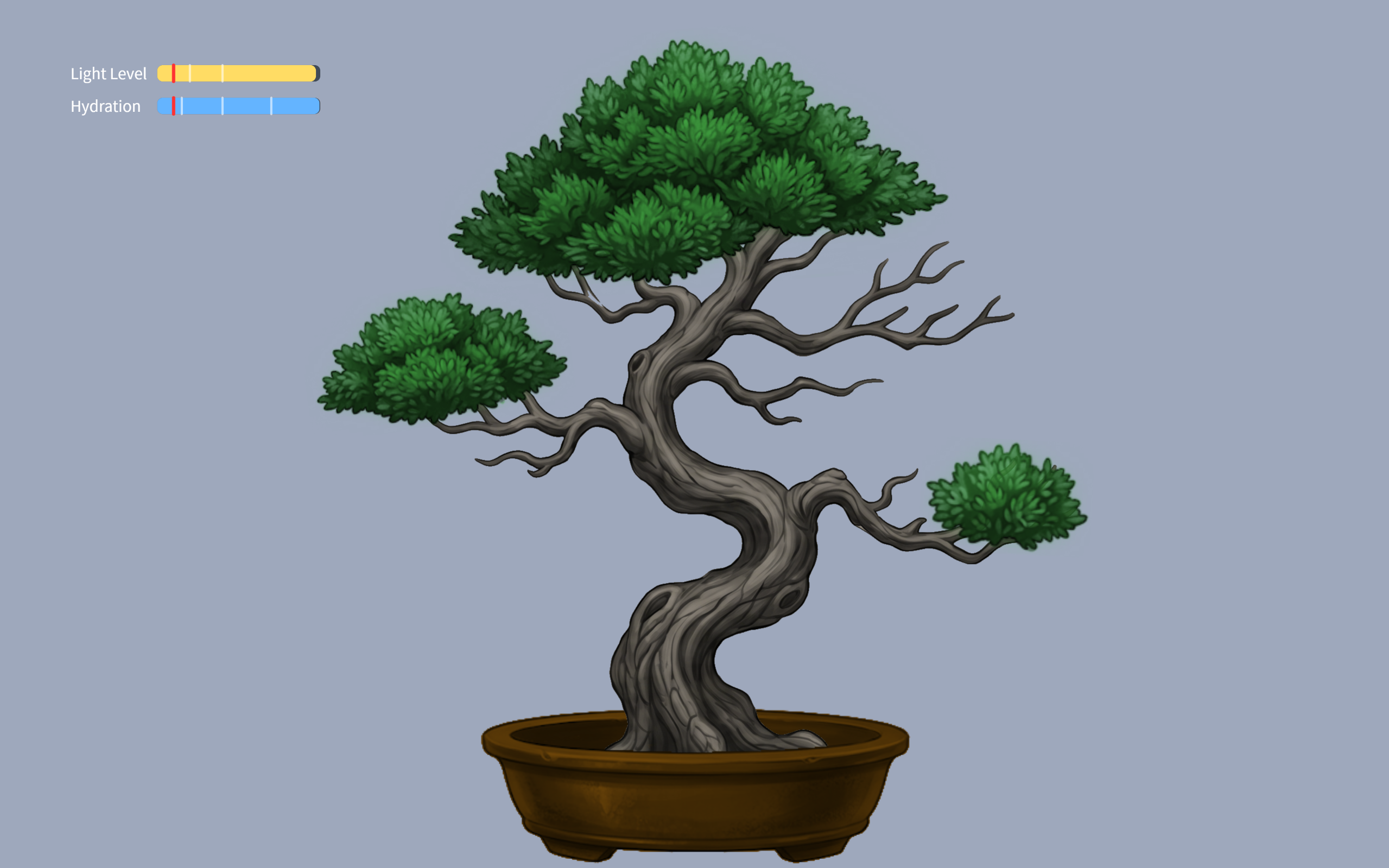
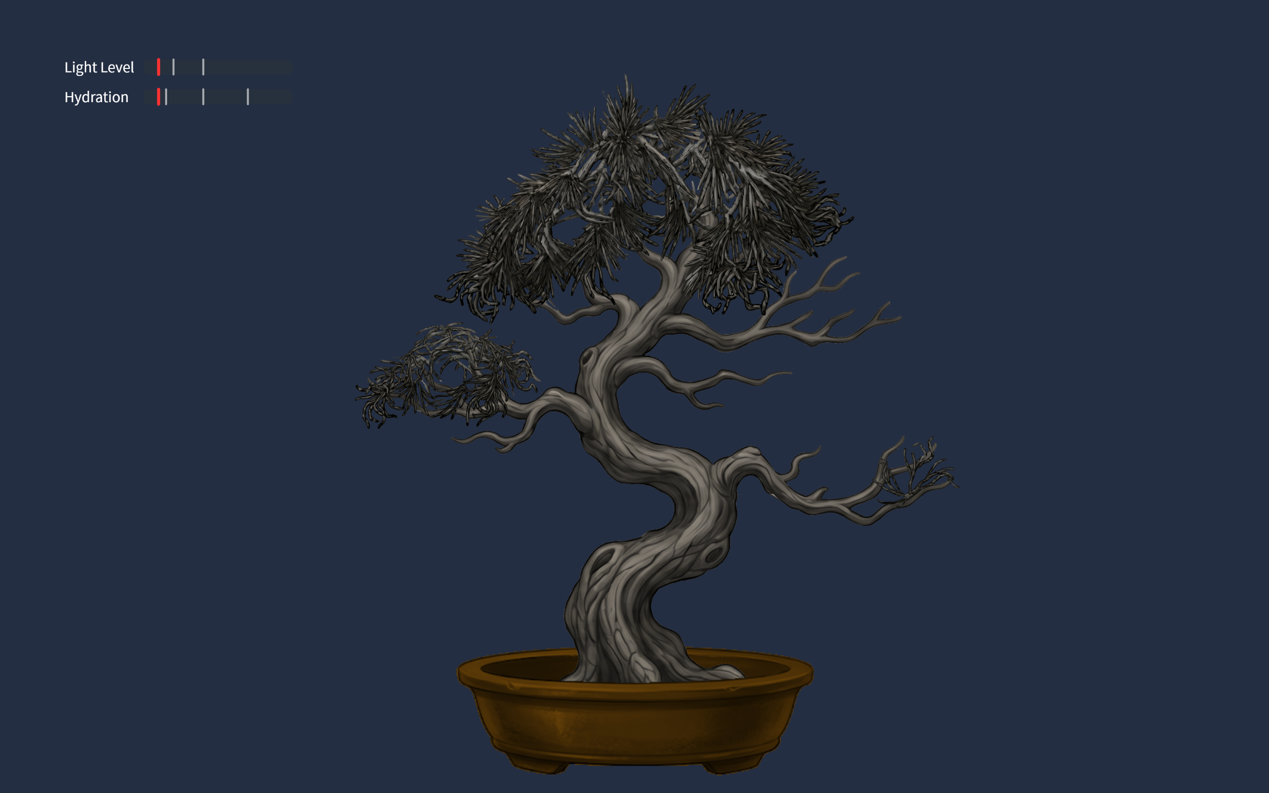
The final project is an interactive experience where the users physical body state and actions of caring for themselves will be interpreted to the growth of a digital Bonsai tree. The users breathing are monitored, to which the tree syncronizes, are interpreted into the growth of the tree. The act of drinking water will serve as hydration of the tree. The physical light conditions of the user’s environment will be reflected on the tree’s lighting conditions. This experience visualizes meditation and self care, turning it into something tangible and fun.

Images of experience

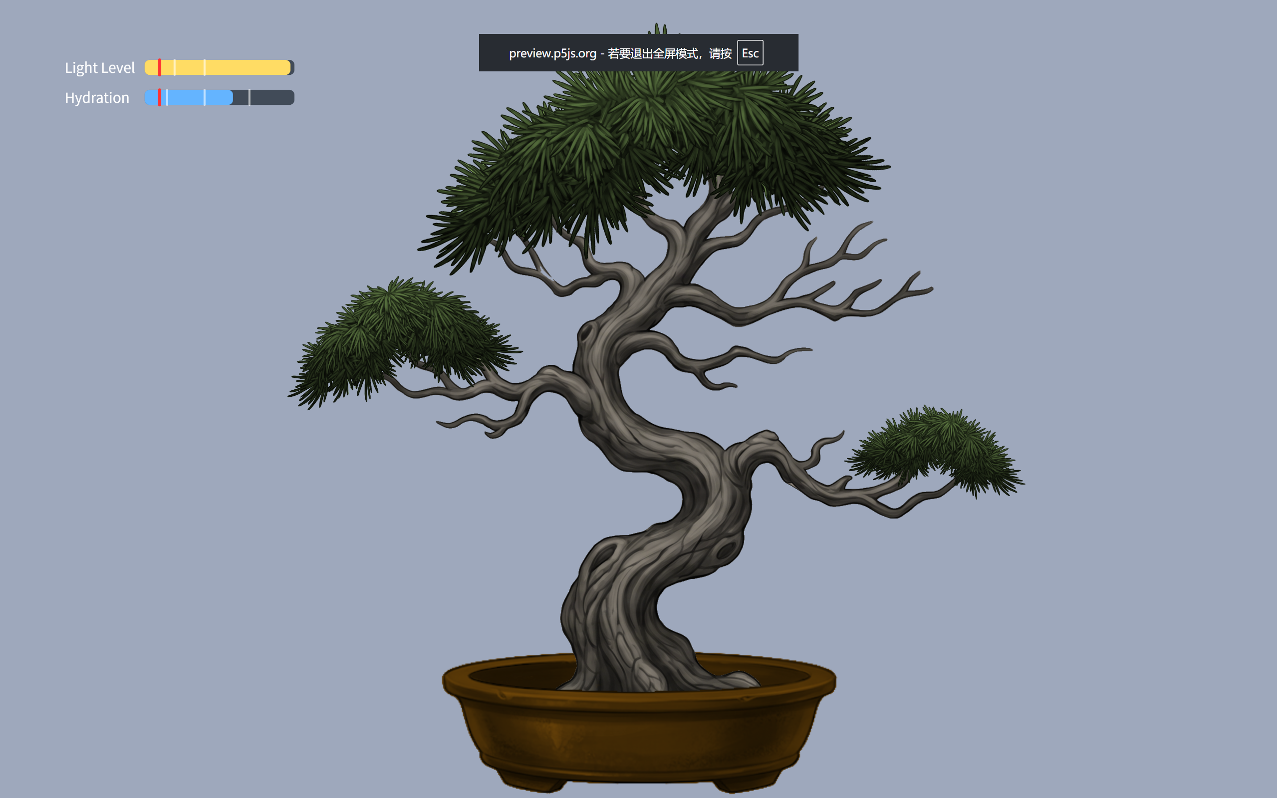
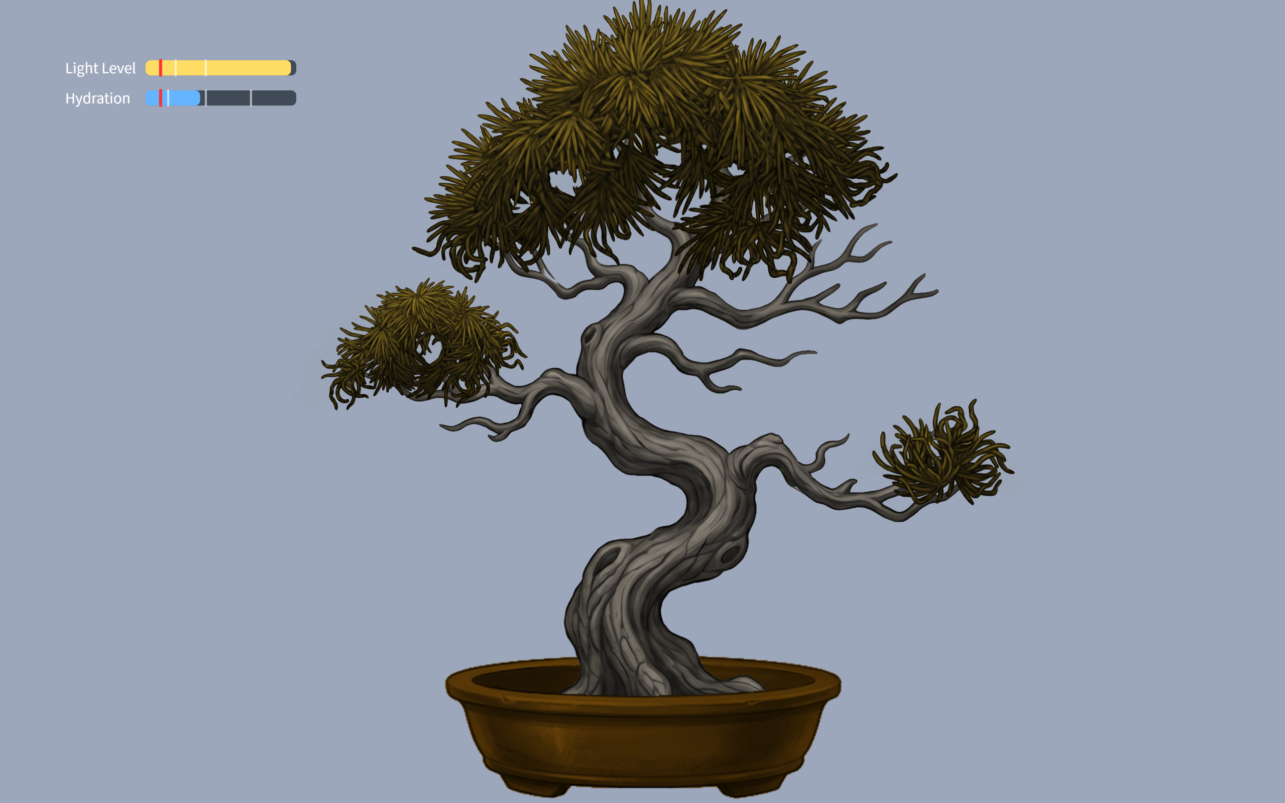
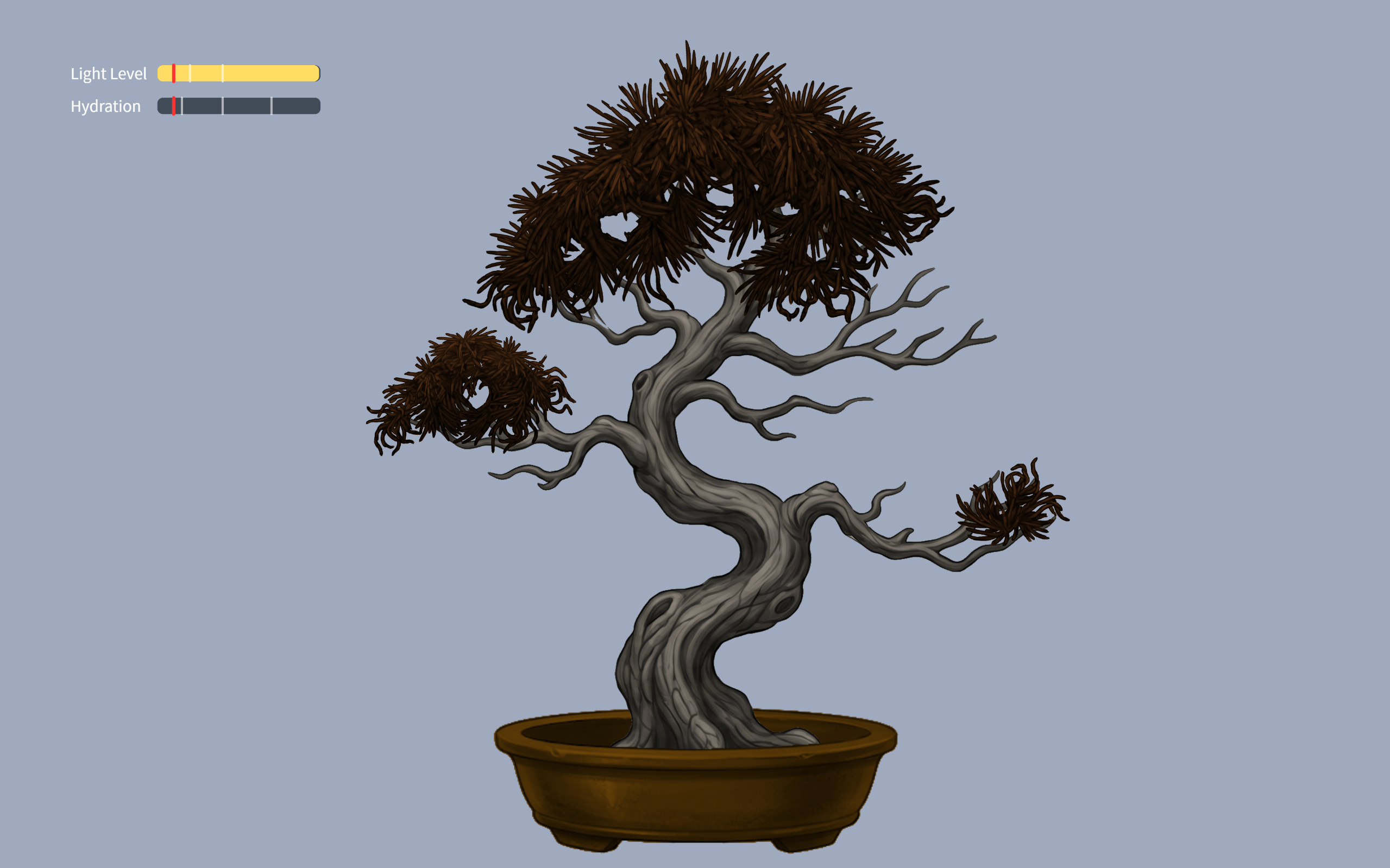
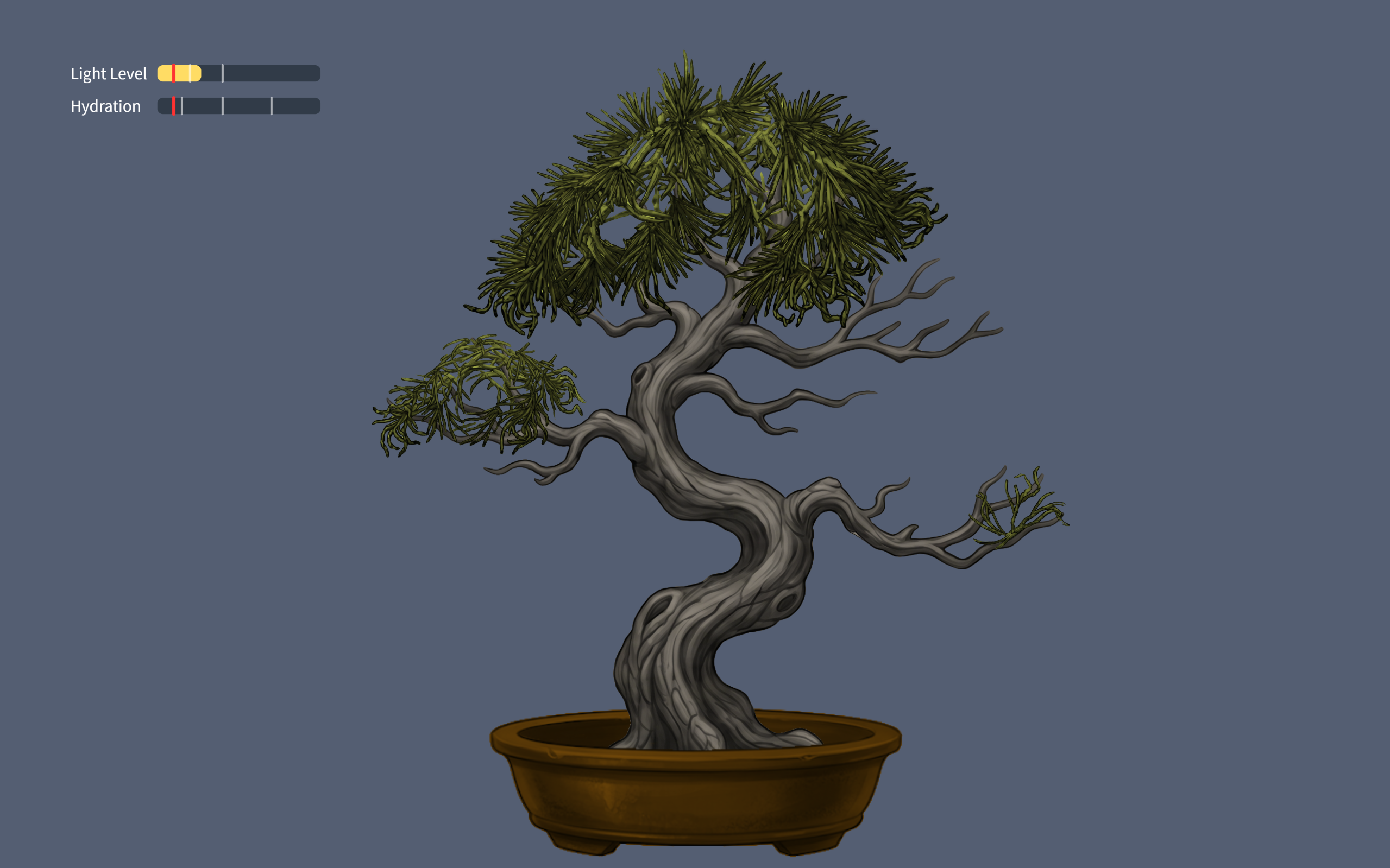
100-70% hydration tree70-40% hydration tree40-15%hydration tree15-0%hydration tree40-20% light tree
0-20% light tree

User testing

Implementations

The design is based on self care of a person, so I need to convert human actions to inputs to the interface. Inputs include the users breathing (analog input), user drinking (digital input), lighting (analog input).

  • Arduino code: My arduino code was realitively simple, it only inlcuded sensors sensing the inputs, and the bidirectional communication handshake.
if (Serial.read() == '\n') {
  digitalWrite(lightLedPin, lightState);
  digitalWrite(breathLedPin, breathState);
  digitalWrite(waterLedPin, waterState);

  // SEND TO P5
  int breathing = analogRead(A0);
  delay(5); 
  int light = analogRead(A1);
  delay(5);
  int sipping = digitalRead(2);
  int buttonState = digitalRead(buttonPin);
    
  Serial.print(breathing);
  Serial.print(',');
  Serial.print(light);
  Serial.print(',');
  Serial.print(sipping);
  Serial.print(',');             
  Serial.println(buttonState);
}

This is just the chunk for sending the data to p5.

github link: https://github.com/JingyiChen-jc12771/Intro-to-IM/blob/bc4afa47ce3d8aa52541bd046100ab28d2794849/final_project.ino

  • p5 code: p5 code is very illuistration heavy, all the animations are in p5. I included callibration to users breathing conditions, the change of tree appearance when parametera changed, and all special effects triggered when drinking or focusing for a certain amount of time.
if (gameState === "instructions") {
  if (breathingValue < userBreathMin) {
    userBreathMin = breathingValue;
  }
  if (breathingValue > userBreathMax) {
    userBreathMax = breathingValue;
  }
}

This is a simple chunk of code where I calibrate the upper and lower limits of users breath strength to each indicidual player behind the instructions. this allows the tree pulsiong to work for everyone, and no one has to worry about being too much a fast breather.

the communication between p5 and arduino is basically arduino sensors sensing the suroundings and sendinbg them to p5 to apply to the art, and when p5’s math calculates that parameters are below 10%, it sends signals to arduino to light up the corresponding LED.

Some aspects that I am proud of

function checkFlowState() {
  if (lightPercent > 80 && hydrationLevel > 80) {
    return true;  
  } else {
    return false;
  }
}
if (checkFlowState() === true) {
   isFlowing = true;
   spawnOrbs();
   growTreeToMax();
} else {
   isFlowing = false;
}

I am sort of proud of this piece of code. I am also proud of the breathing calibraation. This code here is the little “Easter Egg” effect I coded for player who are doing well. As long as they keep themselves and the tree in a good state, little magical balls of forest magic will flout up the screen, as an unexpected surprise.

Sources

https://www.youtube.com/watch?v=WDRokF_ZW9A

https://www.sciencebuddies.org/science-fair-projects/project-ideas/HumBio_p054/human-biology-health/train-belly-breathing?ytid=WDRokF_ZW9A&ytsrc=description

https://www.youtube.com/watch?v=KkyIDI6rQJI

https://www.youtube.com/watch?v=Qf4dIN99e2w

google gemini for image generation

AI use

Google gemini pro 3 helped me with: lerp() to create smoothing of breathing signals, virtual canvas to keep image sizes proportional, fade in fade out effects, understanding the breathing sensor reference code I found, finding correct speeds for parameters, and most importantly finding the cause of bugs.

Challenges

The most difficult part is actually debugging. It was not first writing the code itslef, it is how everything started failing once I initiated the running of the code. The serial communication produced some unexpected problems like not communicating at all or p5 and arduino screaming at each other and calsing the whole game to freeze. the fact that I am relatively new to both, especially arduino, makes it really hard to figure out what is going on in the code.

Future Improvement

What I would want to imporove in the future might be the animations. My current experience is based on images generated by gemini, and the fade in/ fade out effects were not the mast ideal. Though the tree pulses with the user this lack of animation stilkl makes the experience feel less lively. I would hope to ba able to upgrade that to make it more immersive.

Final Project

Concept:

The concept of my game is a ballet opera simulation where the user controls the ballerina’s movements. Using padding on their finger tips, whenever the user presses their fingers together, the ballerina changes positions. If the user is idle or as they call it AFK for too long, the ballerina will fall and the buzzer connected with make a noise

Sketch:

https://editor.p5js.org/da3755/sketches/Za6gDoYXq


Arduino Code:

https://github.com/da3755-ui/intro-to-im/blob/da20ed409cd10566c8e7bb00e641c957f72e08c1/IntrotoImfinalproject_.ino

User Testing:

User Testing 2:

Visuals and More User Testing and Circuit Set Up:

https://drive.google.com/drive/folders/1mwulAEwvxRT4E3LnXxp-2LjqP0v3otrT?usp=drive_link

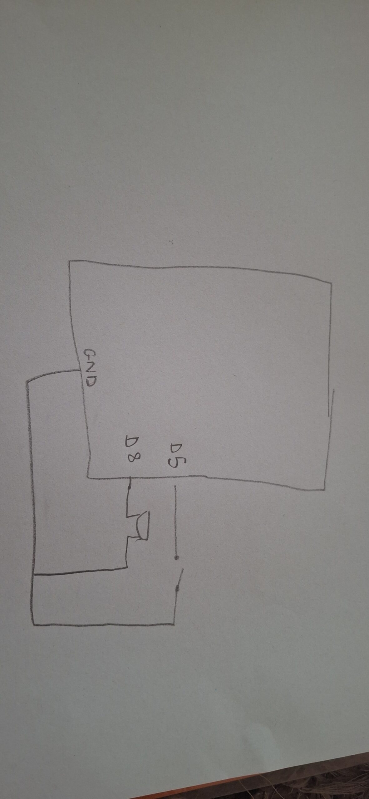
Schematic

Description of interaction design

The game follows a typical bi-directional sequence. The pads of the fingertips are wires connected to aluminum foils that act as a switch when in contact. Once they make contact, for each contact, the spritesheet iterates through itself and plays the next sprite in order.

From p5’s side, I have designed it so that if you go idle for 10 seconds or more, a new spritesheet plays where the ballerina falls, and I send a signal to Arduino to play the buzzer as a “warning”

My p5 code relies on the same game state functions we had in our midterm project, where I move from start –> instructions –> game —> end. I did not use OOP in my project, which I realized a bit too late that it would have been better if I had. I used many, many if statements, which were confusing at times because of their frequency. For my first dancing spritesheet I used the typical nested loop structure we took in class, however for my second falling spritesheet I used a technique I found on YouTube that almost rapidly swipes through the sprites creating the seamless motion.

let data = port.readUntil("\n");

if (data.length > 0) {
  fromArduino = Number(trim(data));

  // Glove touched (movement detected)
  if (fromArduino === 0 && lastGloveState === 1) {
    lastTime = millis();       // reset inactivity timer
    step = (step + 1) % 6;     // advance animation
    gloveCount++;

    if (step === 0) {
      direction = (direction + 1) % 3;
    }
  }

  lastGloveState = fromArduino;
}

From Arduino, I actually faced a lot of problems with my buzzer, it was just constantly ringing the whole time, regardless of me uploading my code onto it or not. I was also initially using the tone() that we took in class but it was honestly just ringing throughout the entire house. I used ChatGPT to ask what the issue was, and it told me I have an active piezo buzzer. So I went on YouTube to understand how to use it and watched a tutorial I used.  I found out that active buzzers use digital readings.

int songStatus = digitalRead(changePoses);

Serial.println(songStatus);

delay(100);

if (Serial.available()) {
  digitalWrite(LED_BUILTIN, HIGH); // led on while receiving data

  int warning = Serial.parseInt();

  if (Serial.read() == '\n') {
    digitalWrite(buzzer, warning);
 
}

The most challenging part was getting both spritesheets to work. I watched several tutorials on how to iterate smoothly between the sprites but it was either they were using p5.play or something called canvas. I kept going through trial and error until I found the right video tutorial. Also sometimes the sprites would not have equal distance between them, so splitting up the spritesheet was difficulty and I had to manually do it using Canva and a spritesheet maker online. Another difficult aspect was the p5 to arduino connection that made the ballerina fall and the buzzer ring. I had the right logic but it was not working correctly until several trial and error and research.

I think I’m most proud of the finger touch detection because it took a lot of trial and error to figure out how to get the detection and I remembered the lastXstate we used in our musical instrument assignment.

An early challenge I had was that the page would not load ever. I tried switching to VS Code to test out if the problem is with p5 or the code. After switching over to VS it still didn’t work. I tried Googling what I could do but it didn’t work. I then played another audio instead to check if the issue is with p5 or with the file, and the other audio played. I then asked ChatGPT and it told its because my audio file’s name is too big.

I also watched a video about how to animate on JavaScript and tried implementing it but it did not work. That’s when I found out it’s because the user was using an application called Canvas which uses certain functions p5 does not have. The code is available on my sketch under index.js but it’s commented out.

Also my buzzer was just constantly constantly ringing without me doing anything, but I was messing around with the wiring before I fixed my code and realized that the buzzer activates itself with just wiring even if I don’t put in code. After I uploaded my code it stopped making a noise.

AND my ballerina refused to fall. After asking CoPilot it told me to incorporate a modulo which is similiar to my time elapsed feature. This way the frames don’t move too fast to see (approx changing in 0.08 seconds).

Future Reflection:

For the future I would love to implement a way to actually be able to assign beats to the finger presses, so the buzzer and falling is more linked to missing or adding a beat than just being idle.

I also wonder if there’s a way to wirelessly connect something to my Arduino, it would have made using the finger pads much easier without having to carry the breadboard and Arduino with me the whole time.

Also I will be fixing certain aesthetic elements such as the font.

References:

AI DISCLOSURE:

AI was used for the following:

  1. generating images, sprites, and backgrounds. It honestly didn’t do the best job with spritesheets. Every sprite was super stuck to the other and the spacing between the sprites were iconsistent, which I had to fix myself.
  2. detecting issues with buzzer. ChatGPT told me its an active piezo buzzer, and gave me ways to troubleshoot and figure out if my buzzer is broken, if there’s a wiring problem, or a problem with the code. It was none of them
  3. debugging code such as declaring booleans i forgot to declared before
  4. fixing animation timing (the ballerina would either never fall or fall then disappear or fall quickly)
  5. I tried using frameRate because that’s what I used when testing out my animation on another sketch, but AI (not sure whether it was ChatGPT or CoPilot) told me that I can’t use frameRate in my code because it resets it for everything in the sketch.
  6. My logic was correct, but not ordered correctly I’m assuming. Honestly, I’m not really sure, I used pretty much the same logic as CoPilot I had more things included but mine didn’t work. I think it’s because the CoPilot added a modulo feature in order to time the animation of falling correctly. This is because when I was adding and removing elements from my code and CoPilot’s, the modulo component was the one that made the difference.
  7. From my observations CoPilot helps better than ChatGPT

https://projecthub.arduino.cc/SURYATEJA/use-a-buzzer-module-piezo-speaker-using-arduino-uno-cf4191

https://forum.processing.org/two/discussion/12119/removing-an-image-once-it-s-drawn.html

https://stackoverflow.com/questions/52133058/how-to-make-my-countdown-timer-dont-start-from-the-beginning-when-refreshing-th

https://p5js.org/reference/p5/background/

https://p5js.org/reference/p5/frameRate/

https://p5js.org/reference/p5/image/

https://github.com/fahadhaidari/game-code-bites/blob/master/spritesheet-animation/index.html

https://forum.processing.org/two/discussion/23003/how-to-use-millis-to-display-images-every-x-seconds.html

https://forum.arduino.cc/t/counting-incoming-signal/663387

https://spritesheetgenerator.online/editor

https://docs.arduino.cc/built-in-examples/digital/toneMelody/

Final Project: Echo Move

CONCEPT

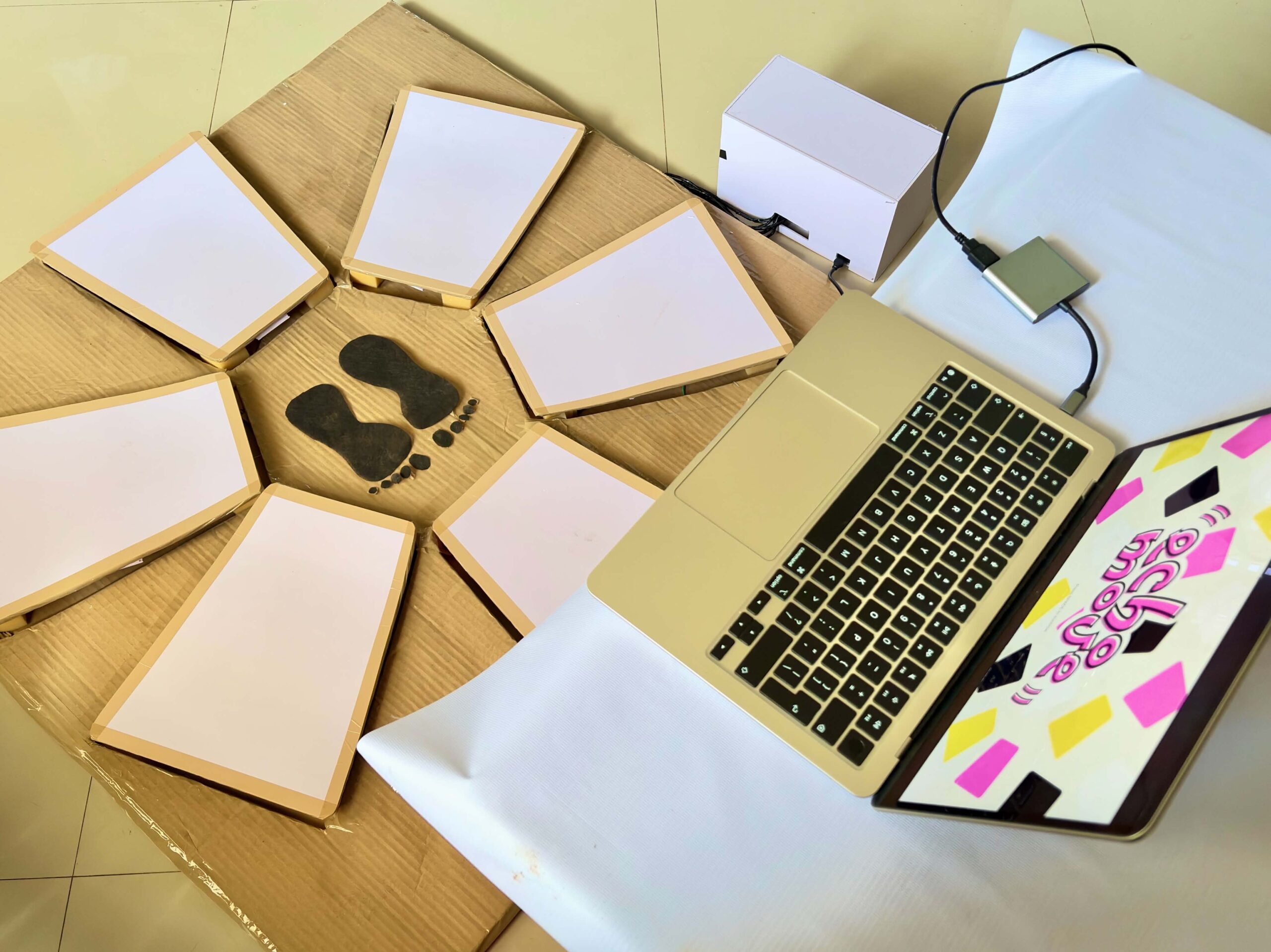
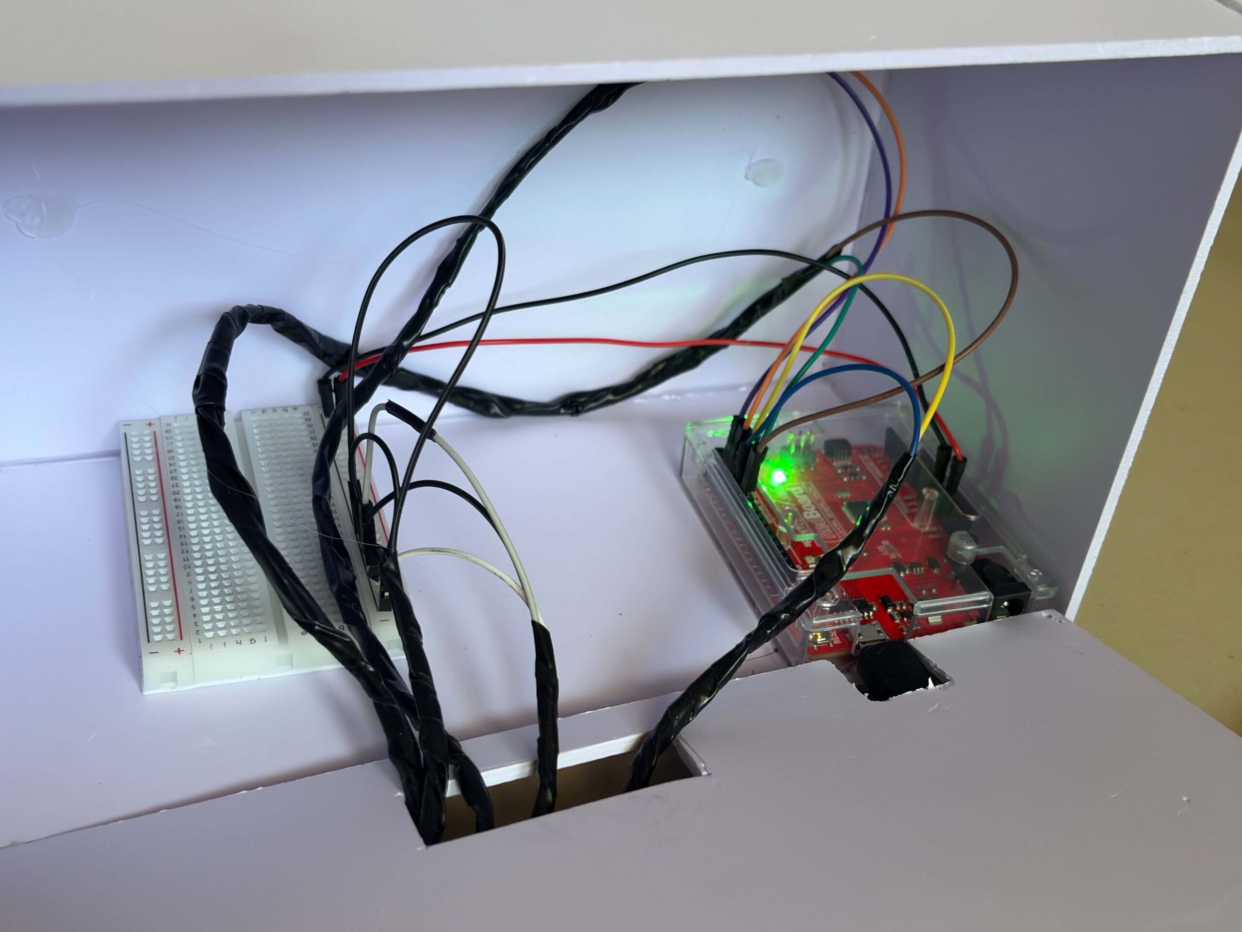
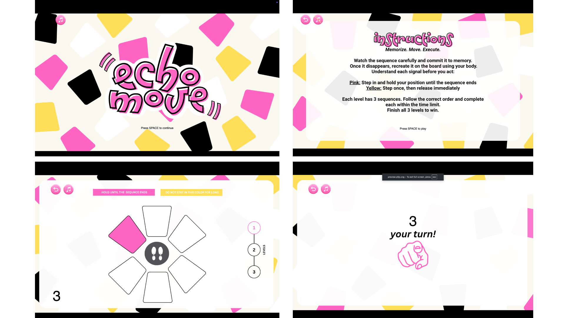
In Echo Move, players are shown a sequence of colored tiles on screen for a few seconds. Once it disappears, they have to recall and perform the sequence using any part of their body on the “Echo Move Board,” which is connected to an Arduino. The challenge is to remember the information and use it accurately on time.

The physical board itself has no colors, only neutral zones. All cues come from the screen, which means players must mentally map what they see onto the board. When the pink color appears in the sequence, the player should step into the zone and hold it until the sequence ends. If it’s yellow, the player should step once and remove it afterward. The game has three levels, and each level gets harder as it progresses. It adds more complex sequences, tighter timing, and trickier signals.


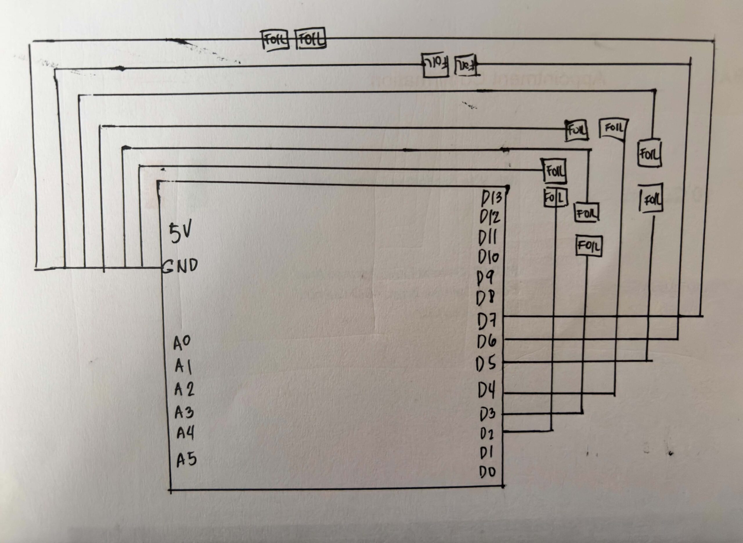
SCHEMATIC DRAWING:

USER TESTING:

HOW DOES IMPLEMENTATION WORK? 

INTERACTION DESIGN – For the interaction design, I first wanted the game to show all the sequences continuously before the player could input them. However, while coding and testing it, I realized it was too difficult, especially because some tiles require multiple holding actions. Because of this, I divided the gameplay into a show phase and an input phase so players can first memorize the sequence, then perform it more clearly one step at a time. I also added countdowns and timers to guide the player and make the gameplay more challenging.

Aside from the spacebar for transitions, most of the interaction happens through the Arduino board, making the experience more physical and interactive. I also added background music and used brighter visuals because I wanted the game to feel lighter and less like a typical arcade game.

ARDUINO | GITHUB

The Arduino code that I used for this project is really straightforward. The code snippet below shows that the Arduino continuously reads each sensor. When a sensor changes from unpressed to pressed, or from HIGH to LOW, it sends the sensor number to p5.js through serial communication.

for (int i = 0; i < 6; i++) { // loops and checks all 6 sensors one by one
   int current = digitalRead(sensors[i]); //checks if sensor is being pressed.

P5 & Code Highlight

The line of code that I was really invested in was this:

this.sequenceIDs = this.sequence.map(img => this.photos.indexOf(img));

I got help from ChatGPT with this code, and it really interested me because it showed me how the game could turn an image into a number that matched my sensors. It helped me understand that the program does not actually recognize the images themselves. Instead, this line turns each image into a number based on its position in the array, and that number is connected to a sensor on the board. This made me realize that behind the visuals, the game is really just comparing numbers between the screen and the Arduino input.

COMMUNICATION BETWEEN P5 AND ARDUINO

While the Arduino handles the physical interaction of the game, P5.js handles the game logic and visuals. The Arduino continuously reads the DIY Foil sensors on the Echo Move board to detect when the player steps or presses on something. Once an input is detected, Arduino sends the data to p5.js through serial communication in real time. When the data reaches P5, it handles the game logic and visuals. It shows the sequence the player needs to remember, reads the inputs coming from Arduino, and checks if the player followed the correct order and actions. Based on the player’s performance, p5.js decides if the player wins or loses and updates the game state on screen, and then sends it back to Arduino, which makes the arduino print it from the serial monitor.

ASPECTS OF THE PROJECT THAT I’M PARTICULARLY PROUD OF

One aspect of the project that I’m particularly proud of is building the circuit and the board itself. As someone who enjoys crafting and making things by hand, I really liked the process of physically putting everything together and planning the wiring underneath the board carefully. I also used my unusual switch setup from my previous assignment, where I used DIY foil sensors and foil as part of the base wiring. Even though I ran into some problems during the process, I’m still really happy with how it turned out. I’m also proud that I didn’t follow a tutorial for the wiring setup and instead figured out most of it on my own.

CHALLENGES FACED

Most of the challenges I faced were during the coding process, and it was the part that took me the longest to finish. Since I couldn’t find tutorials that matched exactly what I wanted to make, I had to combine different references from the p5.js library, past class slides, Arduino cheat sheets, and other online resources.

One of the hardest parts for me was assigning different rules for each color. Originally, I also had a black tile whose rule was to be ignored, but for some reason, it kept causing problems in the gameplay logic. I spent a lot of time trying to fix it, researching solutions, and asking ChatGPT for help, but it still was not working properly. To focus more on the parts of the project that needed more attention and to manage my time better, I decided to remove it from the final version instead.

AREAS FOR FUTURE IMPROVEMENTS

I would like to add more levels and make the sequences more complex. If I had more time, I would also create more animations directly in p5.js instead of designing some visual elements in Canva and loading them as images. This would make the game feel more dynamic and interactive.

SOURCES

https://p5js.org/reference/p5/millis/ , https://editor.p5js.org/enickles/sketches/MBgdwrdPB

https://github.com/liffiton/Arduino-Cheat-Sheet/blob/master/Arduino%20Cheat%20Sheet.svg

.https://www.youtube.com/results?search_query=p5js+memory+game+tutorial

past class slides & previous assignments

USE OF AI

AI tools such as ChatGPT and Claude were mainly used to help me debug and understand my code throughout the project. They helped me figure out why some parts of my code were crashing, locate missing mistakes like semicolons or misspelled words, and understand why some of the logic I wrote was not working the way I expected.

I also used AI to help me understand some code from past class slides and the p5.js library, especially when I was confused about why they did not fully match what I wanted to happen in my own project. In some cases, AI helped me figure out missing logic or missing lines of code that I overlooked while coding. Aside from debugging, I also used AI for cleaning and organizing parts of the code to make it easier for me to understand and manage. 

These are some of the lines of code and sections where AI assistance was directly used:

this.playerInput = (this.phase === "input") ? playerInput : -1;

This line of code really helped me organize the flow of the game better. It made sure that the board only accepts inputs during the input phase, so players won’t accidentally trigger sensors while the sequence is still being shown. I realized this made the interaction feel much clearer and less confusing, especially during testing.

let expected = this.sequenceIDs[this.seqIndex]; // the tile the player is supposed to press at the moment.

     // Hold logic
     if (this.playerInput === expected) {
       this.correctPressed = true; //if the player presses the correct tile, next sequence
       
     }

     if (elapsed >= this.inputTime) { // wait untill 6s ends

       if (this.correctPressed) { //
         this.seqIndex++; // show next sequence tile

         if (this.seqIndex >= this.sequence.length) {

I also had difficulty figuring out how to properly check if the player was stepping on the correct tile in the right order. ChatGPT helped me structure the game logic by comparing the player’s current input with the expected tile from the sequence array. It also helped me understand how to track the player’s progress using seqIndex and how to move to the next sequence only when the correct tile was pressed within the time limit.


Final Project – Brew Your Coffee

Concept:

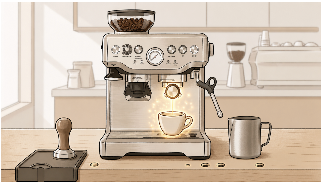
For my final project, I created an interactive simulation called Brew Your Coffee, which the title itself reflects clearly. Inspired by my love of coffee, and specifically the process of making a cup of coffee, I wanted to create an experience where the user could go through a fun and interactive coffee-brewing simulation using both a p5 sketch and Arduino physical components.

The project aims to create a realistic and engaging experience through a self-made coffee machine model that includes actual coffee-making objects and a sensor that detects the user’s physical movements. By following the provided guide and completing each step, the user gets to simulate brewing their own freshly made cup of coffee!

Visual Documentation:

For the main model, I mainly used cardboard. I measured and cut the pieces using a cutter, then assembled and attached them together using a hot glue gun.

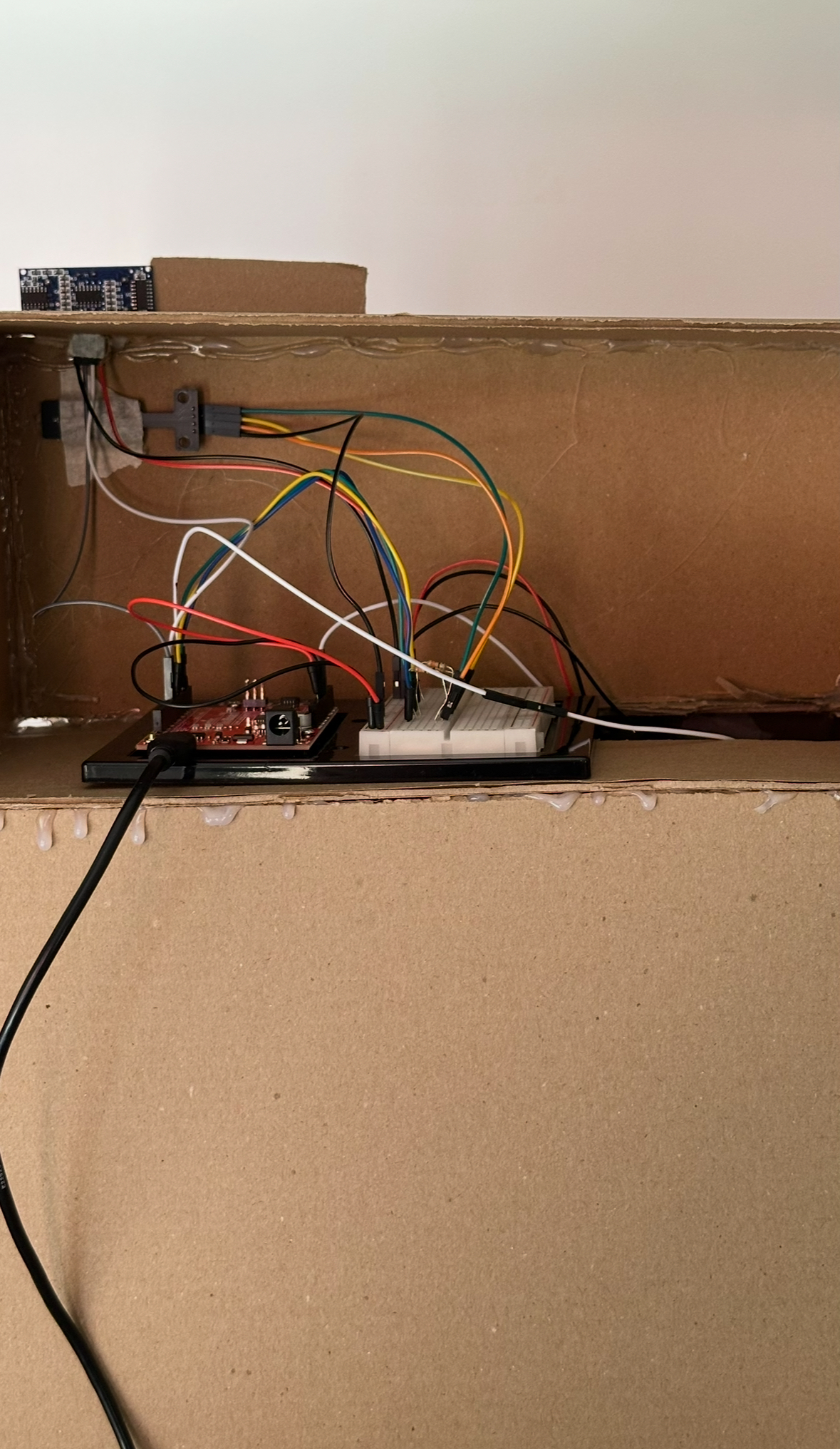
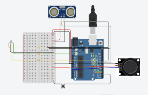
I first created openings for the visible components, including the button, joystick, LED module, and ultrasonic sensor, then started setting everything up using the Arduino, breadboard, jumper wires, and female-to-male jumper wires for the components that needed longer connections.

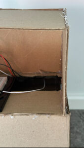
Here is the back of my model showing the wiring setup. The lower opening contains the joystick and button wires extending downward into the popped-out tilted section to make the controls more comfortable and easier for the user to interact with.
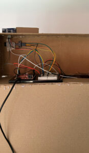
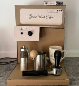
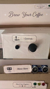
After securing the wiring and making sure the Arduino setup was functioning correctly, I assembled the structured pieces together into the coffee machine model I had envisioned. I then added the title of the simulation as the name of the machine, along with labels for the different components such as the controls, sensor, and LEDs to make the interaction clearer for the user. I also decided to include actual coffee-making objects that matched the visuals shown on the p5 sketch in order to create a more realistic and immersive experience.
Setup:

Fully aligned with the actual arduino:
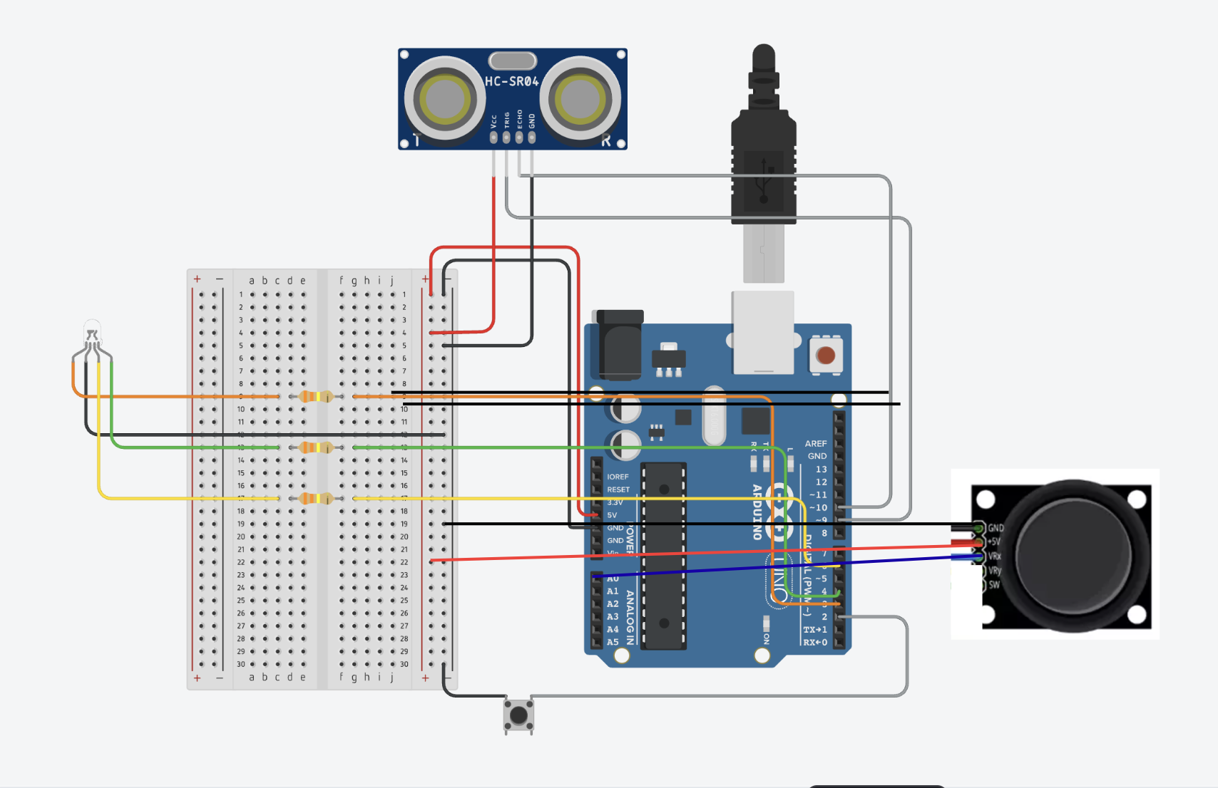
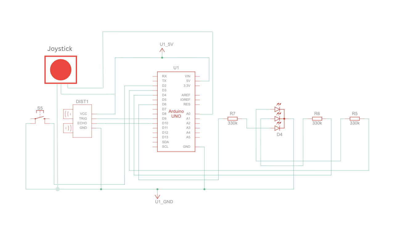
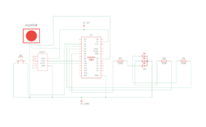
Schematic:
User Testing: 

Interaction design:

The interaction design of my project was created to make the experience feel simple, clear, and realistic for the user. I wanted the interaction to imitate the actual process of making coffee while still being easy and enjoyable to understand.

The user first moves through the different screens using the physical button and joystick attached to the Arduino setup. The joystick allows them to navigate between the coffee-making steps, while the button is used to confirm selections and move forward in the experience.

Once an action begins, the interaction changes from button-based navigation to physical movement. The ultrasonic sensor detects the user’s hand movements in front of the coffee machine model, which then progresses the animations on the p5 sketch with audio. This was designed to make the user feel more involved in the process rather than only pressing buttons on a screen.

The LED lights were also part of the interaction design and acted as visual feedback for the user. Red indicates that the action is ready to begin, yellow shows that movement is currently being detected, and green indicates that the step has been completed successfully. Along with the sprite animations and sound effects, these interactions helped make the experience feel more responsive and immersive.

Arduino code:

The Arduino code handles all the physical interactions of the project, including the joystick, button, ultrasonic sensor, and RGB LED module. It detects the user’s inputs, sends simple serial signals to the p5 sketch for navigation and movement interactions, and receives signals back from p5 to control the LED feedback colors during the experience.

Link to GitHub Code

One of the key parts of the code was the joystick navigation between the coffee-making options. The joystick continuously reads analog values from the X-axis, and depending on the direction the user moves it, the Arduino sends either L for left or R for right to the p5 sketch through serial communication. I also added threshold values and timing delays so the navigation would feel smoother and avoid rapidly repeating the same signal multiple times from one movement. This made the interaction more controlled and easier for the user to navigate.

// Joystick left & right navigation
  int joystickX = analogRead(joystickXPin);

  // Send "L" or "R" when joystick passes threshold, using delay to avoid rapid repeated signals
  if (millis() - lastJoystickTime > joystickDelay) {
    if (joystickX < joystickLeftThreshold) {
      Serial.println("L");
      lastJoystickTime = millis();
    } else if (joystickX > joystickRightThreshold) {
      Serial.println("R");
      lastJoystickTime = millis();
    }

Another important part of the code was the ultrasonic sensor interaction. The sensor measures the distance between the user’s hand and the coffee machine setup. To make the interaction feel realistic, I did not only check the distance itself, but also checked whether the distance was changing enough to count as actual movement. This avoids possible triggering and helped make the animations progress only when the user was actively moving their hand in front of the sensor. I also used threshold ranges and delays to make the motion detection more stable and responsive.

// Movement detection using ultrasonic sensor
  int distance = detectDistance();
  int difference = abs(distance - lastDistance);

  // Send "M" when an object is within range and its distance changes enough to indicate movement
  if (millis() - lastMotionTime > motionDelay) {
    if (distance > minMotionDistance && distance < maxMotionDistance && difference > motionChangeThreshold) {
      Serial.println("M");
      lastMotionTime = millis();
    }

P5.js code:

The p5 code controls the visual and interactive side of the project, including the screens, sprite sheet animations, audio, and overall experience flow. It receives signals from Arduino to activate the interface and progress the actions, while also sending signals back to Arduino to align the LED feedback with the current interaction state.

One of the major parts of the code was creating and controlling the sprite sheet animations for each coffee-making action. I created a class to organize the actions and make each animation easier to manage. The animations work by increasing a progress value whenever movement is detected from the ultrasonic sensor. That progress is then mapped to different frames of the sprite sheet using the map() function. I also used constrain() to make sure the frame number never goes outside the sprite sheet range. Once the action reaches its maximum progress, the animation locks onto the final frame and marks the action as completed.

// Map interaction progress to sprite sheet frames
   this.frame = floor(map(this.progress, 0, maxProgress, 0, this.totalFrames));
   this.frame = constrain(this.frame, 0, this.totalFrames - 1);

   // Lock animation on the final frame once complete
   if (this.progress >= maxProgress) {
     this.frame = this.totalFrames - 1;
     this.done = true;
   }
 }

Another important part of the code was combining audio and LED feedback with the movement interactions. Whenever the user performs movement detected by the ultrasonic sensor, the correct sound effect begins playing depending on the current action. At the same time, the p5 sketch sends signals back to Arduino to control the LED colors. Once the action is completed, the audio stops and the LED changes to green to visually indicate completion to the user.

// Progresses the current action when movement is detected
function handleMovement() {
  let action = getCurrentAction();

  if (action.done) return;

  // Different actions trigger different audio feedback
  if (currentAction === "grinder") {
    grinderAudio.loop();
  }

  if (currentAction === "steamer" && !steamerAudio.isPlaying()) {
    steamerAudio.loop();
  }

  if (currentAction === "coffee" && !coffeeAudio.isPlaying()) {
    coffeeAudio.play();
  }

  action.update();

  // Once the step is completed, stop audio and switch LED to green
  if (action.done) {
    stopAudios();
    sendLed("G");
  }
}

Note: For the audio if statements, the grinder action has slightly different feedback behavior compared to the other two actions. The steamer and coffee audio only begin once the ultrasonic sensor detects movement, while the grinder audio starts when the action screen appears. I made this decision based on the grinder audio file I used, since its first few seconds are mostly silent before the grinding sound begins, which ended up aligning naturally with the user’s interaction timing.

Communication between Arduino and p5.js:

The communication between Arduino and p5.js in my project works through serial communication. The Arduino is responsible for handling all the physical interactions, such as the joystick, button, ultrasonic sensor, and LED lights, while the p5 sketch controls the visuals, animations, states, and audio on the screen.

The Arduino continuously sends simple letter signals to p5 depending on the user’s interaction. For example, when the button is pressed, Arduino sends a signal to move between screens or confirm a step. The joystick sends left and right signals to navigate between the coffee-making options, while the ultrasonic sensor sends movement signals to progress the animations during the actions.

At the same time, p5 also sends signals back to Arduino to control the LED lights. Different letters are sent depending on the state of the interaction, such as red when an action starts, yellow while the user is actively moving, and green once the action is completed.

This communication allowed both the physical Arduino setup and the digital p5 sketch to work together as one interactive system.

Aspects of the project I’m proud of:

One of the aspects I am most proud of is being able to successfully combine the visuals, interaction, and physical setup into one engaging experience. I am especially proud of finalizing the images and coding the interaction between the p5 sketch and Arduino components in a way that felt smooth, interactive, and enjoyable for the user.

I am also particularly proud of using sprite sheets and audio together to visualize movement and actions throughout the coffee-making process. Since this was completely new to me, it required a lot of experimenting, troubleshooting, and problem-solving, but I was very happy to eventually make the animations and interactions work together in a realistic and immersive way.

In addition, I am proud of my physical coffee machine model and how it turned out visually. At first, building the structure felt very challenging and almost impossible, especially because I wanted it to resemble a real coffee machine. However, through patience, planning, and problem-solving, I was able to successfully complete the model and add visual details and labels that improved both the aesthetic and the user experience.

Challenges faced and how I tried to overcome them:

Honestly, working on this project was a rollercoaster ride. Some parts went smoothly, while others were much more challenging than I expected. Most of the challenges I faced were related to the visuals and animations of the p5 sketch, especially because I created all of the images and sprite sheets from scratch using AI while still trying to achieve a very specific vision and aesthetic.

At first, the visuals were not working well and did not look as appealing or consistent as I wanted, especially the sprite sheet animations. To overcome this, I became extremely specific with the prompts and references I provided. I used exact images of the real coffee-making items I had and carefully described the animation style and movement I was aiming for. Even after that, creating the sprite sheets required a lot of patience, since many results came out incorrect or inconsistent. Eventually, after multiple attempts and feedback from the professor, I was able to achieve a result that matched my vision much better.

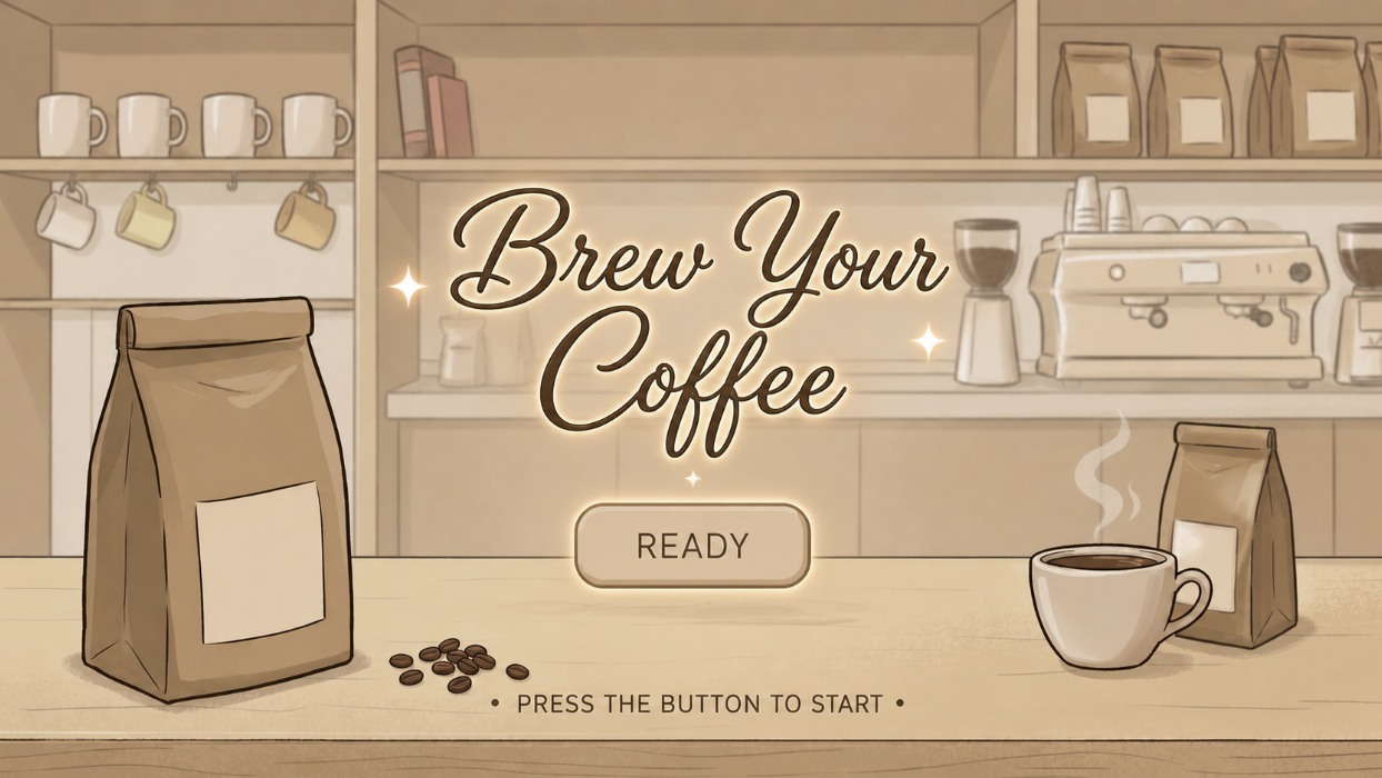
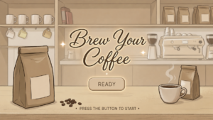
Here are some images from my p5 sketch. All of these screens and interactions can also be fully experienced directly through the embedded p5 sketch:
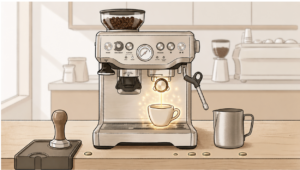
Another major challenge was aligning and displaying the sprite sheets correctly inside the p5 sketch. Some frames would shift position, go off screen, or get cropped incorrectly during the animations. At some points, multiple sprites would appear at once, while other frames looked unaligned or partially cropped. To solve this, I watched tutorials, reviewed references, and experimented with frame sizing, cropping, and scaling until I fully understood how sprite sheets and frame positioning worked within my code. This process helped me improve the consistency and quality of the animations.

// Frame widths based on each exported sprite sheet
  getFrameWidth() {
    if (this.name === "tamper") return 1040 / 7;
    if (this.name === "grinder") return 989 / 7;
    if (this.name === "coffee") return 612 / 6;
    if (this.name === "steamer") return 774 / 8;
  }

// Select the current frame from the sprite sheet
    let cropX = round(this.frame * frameW);
    let cropY = 0;
    let cropW = round(frameW);
    let cropH = frameH;

    let spriteW = cropW * scaleFactor;
    let spriteH = frameH * scaleFactor;

    // Center sprite on screen
    let spriteX = width / 2 - spriteW / 2;
    let spriteY = height / 2 - spriteH / 2;

    // Tamper sprite sheet needed slight position adjustment
    if (this.name === "tamper") {
      spriteX += 80;
      spriteY += 20;
    }

Note: For the frame widths, I used another website called Photopea to calculate how many pixels wide each sprite sheet was, then divided that value by the number of frames to calculate the width of each individual frame. I then continued experimenting and adjusting the positioning and scaling until the animations appeared more consistent on screen.

The tamper action also has an individual adjustment at the end to slightly change its X and Y position, since that specific sprite sheet frames were more visually unaligned compared to the others.

Implementing Feedback:

During the first user testing drafts, I had a user try my project and noticed two important improvements that I should make, which I then implemented into the final version.

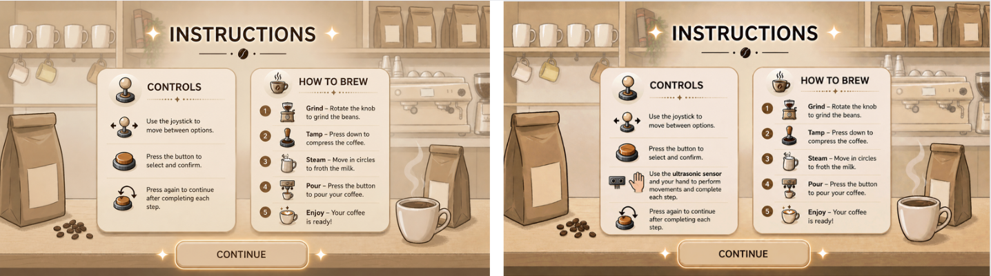
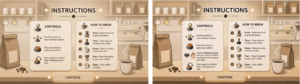
First, I added the ultrasonic sensor to the instructions page so the user would clearly understand where to place their hand and how to interact with the movement actions. Here is the before and after of the instructions page:
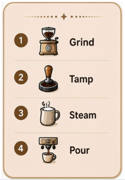
Second, I added a short step guide on the main setup screen so the user could quickly remember the coffee-making order in case they forgot the steps during the interaction. I created the mini guide visually, then coded it to only appear on the main setup screen and adjusted its position to fit naturally within the interface. Here is the mini guide and its code:
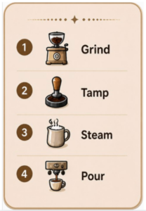
// Display mini guide only on the main setup screen
    image(miniGuide, width * 0, height * 0, width * 0.2, height * 0.35);
  } else if (state === "action") {
    getCurrentAction().display(bg);
  } else if (state === "end") {
    endScreen.display();
  }
}

Areas for future improvement:

Overall, I feel very satisfied with my final result, and I am proud of myself for making my idea work, especially because it was much more challenging than I initially expected. However, there are still areas that could be improved.

I think I could make the experience feel even more realistic by creating longer and more detailed sprite sheets with smoother movement to better represent the live coffee-making actions. I would also like to improve the physical setup by creating a more visually appealing coffee machine model and refining the overall presentation of the interaction.

Since I struggled a lot with the sprite sheets during this project, I think learning how to manually create and align them myself in the future would make it much easier to keep the animations more stable and consistent. It would also give me more control over the positioning, scaling, and overall quality of the animations.

For the future, I would love to create more simulations and interactive ideas using communication between p5 sketches and Arduino. I would also like to explore something more game-based to make the experience even more exciting, such as a café challenge game where the user has to prepare and serve orders for customers. I could even expand the idea further into a full restaurant simulation with multiple menu options and interactions.

Resources:

Arduino:

For my Arduino code, I mostly used the templates we were given in class to understand the structure, along with the official Arduino references to understand specific functions and actions I needed:

https://docs.arduino.cc/language-reference/en/functions/digital-io/pinMode/ 

https://docs.arduino.cc/language-reference/en/variables/constants/inputOutputPullup/ 

https://docs.arduino.cc/language-reference/en/variables/data-types/unsignedLong/ 

https://docs.arduino.cc/language-reference/en/variables/data-types/bool/

I also watched some tutorials for additional understanding:
https://youtu.be/KGwtit2bFyo?si=Fyh10tn7at7zFYyo https://youtu.be/vo7SbVhW3pE?si=PoRPErpxfsdc1cs5 

P5:

For the p5 code, I mostly looked back at our lecture slides and what we covered in class, and I also referred to some of my previous sketches. I used the official p5 references to review and better understand specific commands:

https://p5js.org/reference/p5/image/

https://p5js.org/reference/p5/floor/

http://p5js.org/reference/p5/constrain/

I also watched multiple tutorials to help me achieve the visual actions and sprite animations I wanted:
https://youtu.be/lT_q-ylhML0?si=pfqHTvgWGA_ONRQn https://youtu.be/i2C1hrJMwz0?si=QiOL9T3fHeHro-4e
https://youtu.be/Pn1g1wjxl_0?si=YPGGnEIVbr6oa3yt

Connections:

For the Arduino and p5 communication, I mainly referred to the serial communication slides we covered in class, along with these videos for additional understanding:
https://youtu.be/MtO1nDoM41Y?si=KiDzo6fA5sIav8xj https://youtu.be/MHJ6KpgE7j4?si=lm94nLPvr4QUqhRO 

Referencing of use of AI tools:

I also used AI for support once I faced issues with my code. One major example was when I had trouble with the sprite sheets, as mentioned above, since they would completely go off screen or get cropped during some frames no matter what I tried. After reviewing references and tutorials, AI specifically explained how sprite sheets worked in my context, and that the main issue was related to cropping and frame sizing within the sprite sheets. It guided me through the process of fixing and improving them.

After experimenting with frame calculations and sprite sizing myself, AI further helped explain how sprite sheet cropping, scaling, and frame positioning worked in my specific setup. AI further helped explain how sprite sheets function using total pixels divided by frames, and how functions such as getScaleFactor() could help visually adjust and balance each animation more consistently on screen.

Most of the actions improved after that except for the tamp action. I explained the issue I was still facing, and it walked me through it, leading me to use a specific if statement for the tamping action to adjust its X and Y position separately from the other animations. Here:

// Tamper sprite sheet needed slight position adjustment
    if (this.name === "tamper") {
      spriteX += 80;
      spriteY += 20;
    }

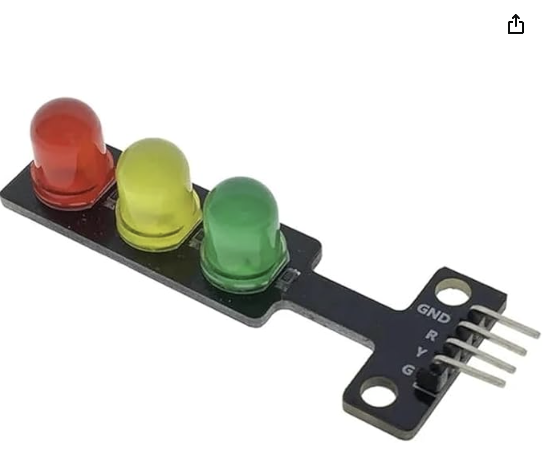
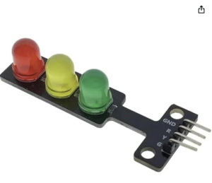
I also used AI assistance while working with the RGB LED module, since I could not find tutorials that matched the exact LED model and interaction style I wanted. It helped me understand how the 4-pin RGB LED worked in my specific setup, how to wire it correctly with Arduino output pins, and how to match the LED colors with the p5 states through serial communication. This is the one I used:
I also used AI to help generate the visuals for my project. I described the exact theme, colors, layout, and style I wanted, then kept refining each image until it matched my vision. This was mainly used for the instructions page, setup screen, and the detailed images for each step. I specifically directed what elements and style I wanted included in each visual.

In addition, I used AI to help create the sprite sheets because I could not find ready-made ones that matched the specific aesthetic and coffee-making actions I wanted for my project.

Final Project — The Grove

1. Sketch, Code, and Clips

Repository

2. Concept

The Grove started as a browser-based resource management game built in P5.js for the midterm. The player tends to a small world made up of five locations — a world map, a river, a forest, a pottery studio, and a greenhouse — collecting materials, crafting pottery, and growing plants in a chain of interdependent steps.

For the final, the question was how to make the act of playing feel less like operating a computer and more like tending to something real. The answer was to rebuild every major interaction as a physical action. Shaping a pot became a gesture over a sensor. Watering a plant became literally pouring water. Digging for clay meant pressing a shovel into a contact board on the table.

The design principle throughout was physical metaphor — every sensor and prop was chosen because the physical action it captures mirrors what it triggers in the game. The player never uses a mouse or keyboard during gameplay. The entire installation is built around five physical components, each assigned to a specific location and moment in the loop.

3. Interaction Design
Joystick — Universal Navigation

A standard analog thumbstick module is the only navigation device in the game, replacing the mouse entirely. It handles all scene transitions, menu navigation, and in-scene cursor movement.

    • On the Map, left and right cycle through locations (Studio, Greenhouse, Forest, River). Pressing the button enters the selected location.
    • In any scene, pushing up enters the upper HUD zone where Return to Map and Menu buttons are highlighted. Pushing down enters the lower HUD zone (inventory). The button confirms the highlighted element.
    • In the Studio, left and right switch focus between the pottery wheel and the furnace.
    • In the River and Studio (when carrying a pot), the joystick moves a virtual cursor freely around the scene rather than switching focus.
    • In the Greenhouse, the joystick navigates a 4×8 grid of planting slots. Pushing up from the top row enters the upper HUD; pushing down from the bottom row enters the lower HUD.
    • In menus, up and down cycle through options and the button confirms.
Proximity Sensor — Pottery Wheel

An HC-SR04 ultrasonic sensor is mounted face-up at the Studio zone. To shape a pot, the player holds both hands above it with palms facing down, mimicking the gesture of cupping clay on a wheel. The closer the hands, the faster the pot advances through its shaping frames — making the interaction feel responsive and skill-based rather than binary. Pulling hands away pauses progress mid-shape.

Potentiometer — Furnace

A rotary dial at the Studio zone controls the kiln. Turning it up starts the fire, which loops the furnace audio and begins cooking the pot. The player watches the pot sprite on screen and turns the dial down to stop firing. If turned off in the right window (10–15 seconds), the pot is finished and ready to collect. Leave it too long and it burns, then turns to ash. The pot can only be picked up once the fire is off.
Conductive Shovel & Digging Board — Forest

A hand-sculpted clay shovel with an aluminum foil tip is used to dig for resources. A flat board on the table has five aluminum contact points — four corners and a center — each wired to a separate Arduino pin. When the shovel tip touches a pad, the circuit closes and the Arduino registers which plot was hit. Each plot is randomly assigned as clay or soil on every spawn and respawn. The player checks the screen to see what is at each spot before digging. Contact must be held for 200ms to prevent false triggers from grazing.

[Include schematic or photo of the digging board here]

Water Sensor — Greenhouse

A water sensor sits under a cup with the bottom cut out. After placing a seed in a greenhouse slot using the joystick, the player physically pours water into the cup. This is the only thing that triggers the watering animation and starts the plant growing. Pouring before planting discards the pour — the water only counts if there is a seed waiting for it. A debounce suppression prevents the sensor from re-triggering while the cup is still draining.

4. Arduino Code
Overview

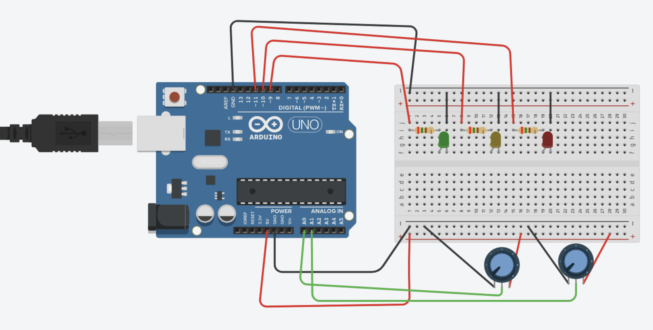
The Arduino acts purely as a sensor hub. It reads all five physical inputs every loop iteration and transmits them as a single comma-separated line over serial at 9600 baud. It contains no game logic — all decisions about what sensor values mean are handled in P5.

Serial output format (11 fields, newline terminated):

joyX, joyY, joyBtn, proximity, potValue, waterValue, dig0, dig1, dig2, dig3, dig4
Pin Assignments
    • A0 – Joystick X axis
    • A1 – Joystick Y axis
    • A2 – Potentiometer (furnace dial)
    • A3 – Water sensor
    • D2–D6 – Dig contact points (INPUT_PULLUP), dig0 through dig4
    • D7 – Joystick button (INPUT_PULLUP)
    • D8 – HC-SR04 TRIG
    • D9 – HC-SR04 ECHO
Key Design Decisions
    • Proximity sensor: a rolling average of 5 readings is taken per loop call rather than averaging in a single blocking call, keeping loop time below 30ms.
    • Shovel contact: each pin must read LOW for 200ms continuously before the event is sent, preventing false triggers from brief grazes.
    • Water sensor: readings are suppressed for 4 seconds after a valid pour, giving the cup time to drain before the sensor is re-read.
    • Joystick: values are sent raw (0–1023 on each axis). Debounce and direction interpretation are handled on the P5 side.
4. P5.js Code
Architecture

The game is structured across seven files. globals.js declares all shared state. classes.js defines Plant, WateringEvent, and ResourcePlot. input.js handles serial communication, joystick reading, and all interaction logic. screens.js handles all scene rendering. audio.js manages background music and plant updates. ui.js provides HUD helpers, button drawing, and the reset and instruction functions. sketch.js is the P5 entry point.

Two stacked state variables drive everything. gameState controls the meta level (title screen, instructions, gameplay, pause). currentLayer controls which physical location the player is in. Every frame, draw() reads both and routes rendering and input accordingly.

Focus System

Rather than tracking a mouse position, the game maintains a focusZone variable (MAIN, UPPER_HUD, or LOWER_HUD) and a focusIndex within that zone. The joystick moves focus between zones and elements. The button always triggers whatever is currently focused. Each scene defines its own focusable elements and navigation rules. A pulsating orb drawn at the focused element gives the player constant visual feedback about where they are.

Virtual Cursor

In the River scene and when carrying a pot in the Studio, the joystick operates as a free-moving virtual cursor rather than a focus selector. A joyVirtualX and joyVirtualY position is updated every frame by mapping joystick deflection to a pixel-per-frame speed. This gives those scenes a more direct, physical feel.

Greenhouse Watering

The plant growth system uses a waiting flag on the Plant class. A plant created by joystick button press sets waiting = true, which causes update() to return early — the plant is visible on screen but frozen. The waterPoured flag is set exclusively inside parseSerial() when the Arduino sends a water reading above the threshold, using rising-edge detection to fire only once per pour. When waterPoured is true and a pendingWaterPlot exists, the watering animation plays and the plant’s waiting flag is cleared, starting its growth timer from that moment.

Furnace State Machine

The furnace moves through six states: EMPTY, PLACED, FIRING, READY_TO_COLLECT, BURNT, and ASH. A pot placed in the furnace starts in PLACED and waits for the potentiometer to cross the threshold before FIRING begins. While firing, the timer runs and sprite frames advance. Turning the dial down while the timer is in the 10–15 second window moves the state to READY_TO_COLLECT. The pot can only be collected when the fire is off. Leaving the fire on past 20 seconds burns the pot.

5. Arduino–P5 Communication

Communication runs over USB serial using the p5.webserial library. On game startup, a Connect Controller button appears below the canvas. Clicking it opens the browser’s port picker. Once connected, the port reads data at 9600 baud using port.readUntil(‘\n’), called every frame from draw(). Complete lines are passed to parseSerial(), which splits the CSV string and populates the sensorState object. All game code reads from sensorState rather than directly from mouse or keyboard events.
The Arduino sends one line every 50 milliseconds, giving approximately 20 updates per second. This is fast enough that joystick input feels immediate and proximity sensor changes are smooth.

No data is sent from P5 back to the Arduino. The Arduino has no awareness of the game state — it only reads and transmits. All interpretation happens in P5.
6. What I’m Particularly Proud Of
    • The physical metaphor is consistent throughout. Every prop was chosen because the action it requires mirrors what it does in the game — pouring water waters the plant, shaping clay shapes the pot.
    • The proximity-to-speed mapping on the pottery wheel. The closer your hands, the faster the pot forms. It makes a sensor interaction that could have been a simple on/off feel genuinely expressive.
    • The digging board and shovel as a circuit. The shovel is hand-sculpted clay with foil on the tip. The board has five foil pads. It looks like a prop from the world of the game, not a piece of electronics.
    • The watering system once it was finally correct — requiring a physical pour after placing a seed, with no false triggers and no carry-over between plants.
    • The overall installation feel. The game is played at a table with different physical zones for each location. Moving between scenes means physically shifting attention to a different part of the table.
7. Areas for Future Improvement
    • A spinning pottery wheel. The original vision included a small DC motor mounted beneath the wheel prop that would spin when the player cupped their hands over the proximity sensor. The motor would start when hands are detected and stop when they pull away, making the physical prop respond to the same input that drives the on-screen animation. This felt like one of the most natural extensions of the project but was cut due to time and the complexity of integrating motor control alongside the existing sensor setup.
    • Better failure feedback. When a planting action fails due to missing resources, nothing happens. A soft error tone or a brief highlight on the backpack would communicate the missing ingredient without breaking the calm.
    • The laptop-on-wheels concept. A motorized platform that rolls the screen to whichever table zone the player enters was part of the original design. A wheeled platform with powerful motors and zone-to-zone timing is buildable but was scoped out due to time.
    • Coordinate normalization. Every scene position is a hard-coded pixel value on a 1024×576 canvas. Normalizing all coordinates to proportions of width and height would make every scene scale to any display automatically.

Final Blog Post :( Final Project Documentation

La Parisserie – A Parisian Croissant Bakery

*credits to my neighbor for the bakery name 🙂

Concept

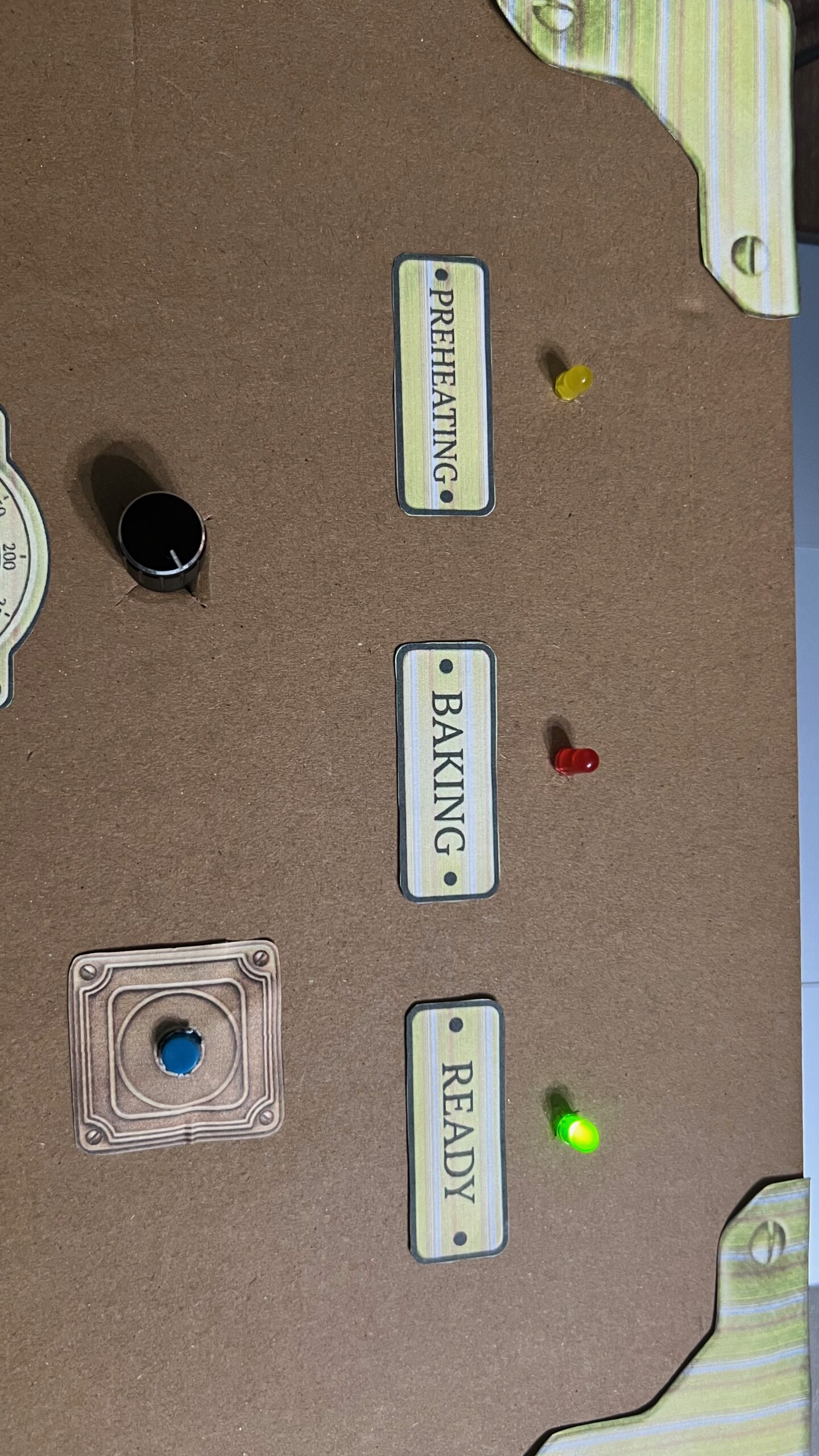
My final project is a croissant baking game, inspired by the best croissants I’ve ever had during my study abroad semester in Paris last year. The player’s task is to bake the croissant’s in the oven and take them out as soon as they become golden and crispy, avoiding taking them out when they are underbaked or burnt. The player gets to control the oven’s temperature, which is linked to how fast the croissants bake, using a 360º rotating dial. Burning the croissants costs you a life. You get three lives in each round. Once you lose all three lives, you lose the game. The final step is for the player to place the croissants in the correct position on a display tray to get them ready for sale. The player must place the falling croissants as soon as they hit their target spot on the tray. A missed target is a lost life.

Demo of Game

p5 Sketch + Arduino Code

Images of Control Box

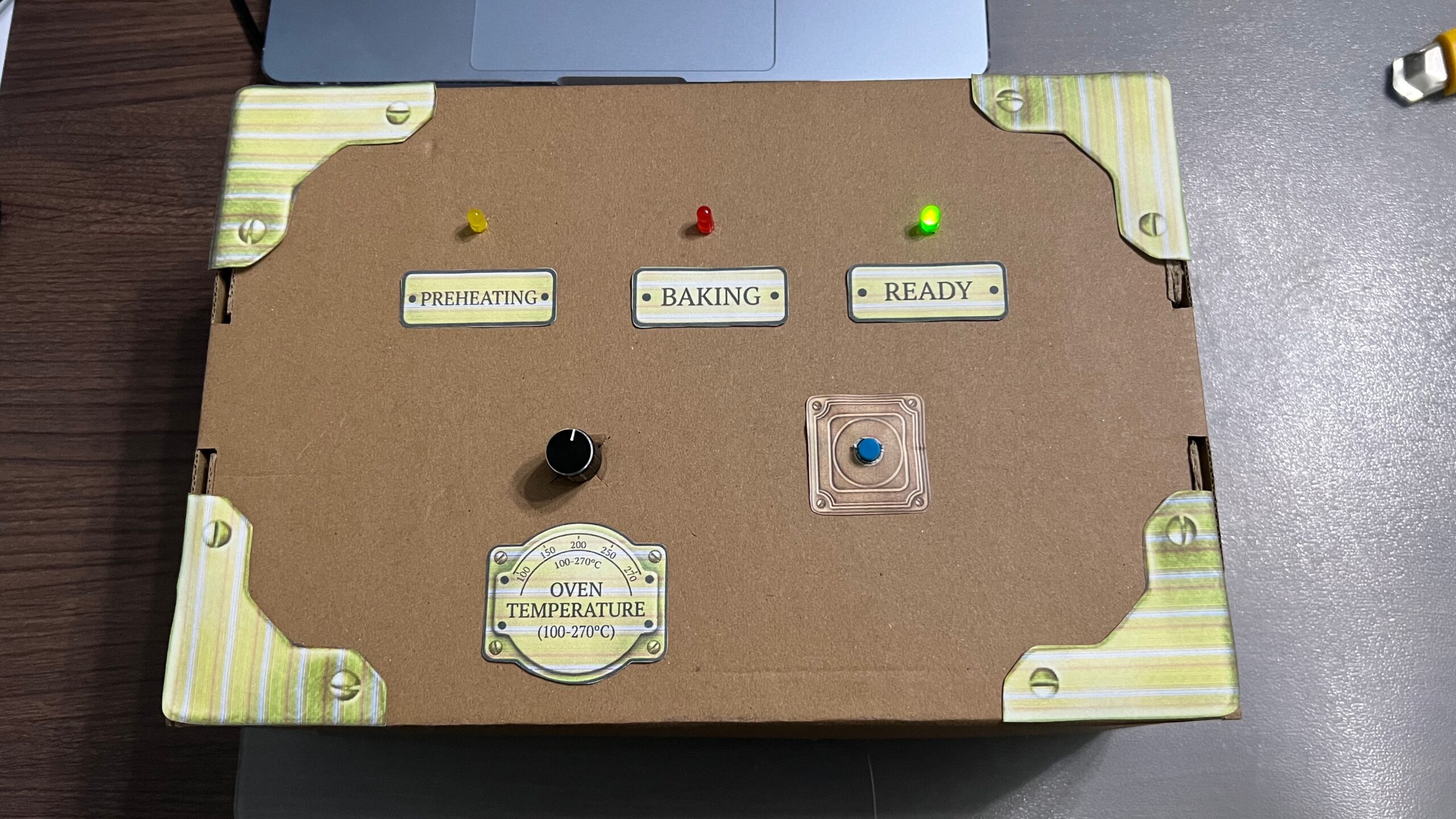
Control box set up:

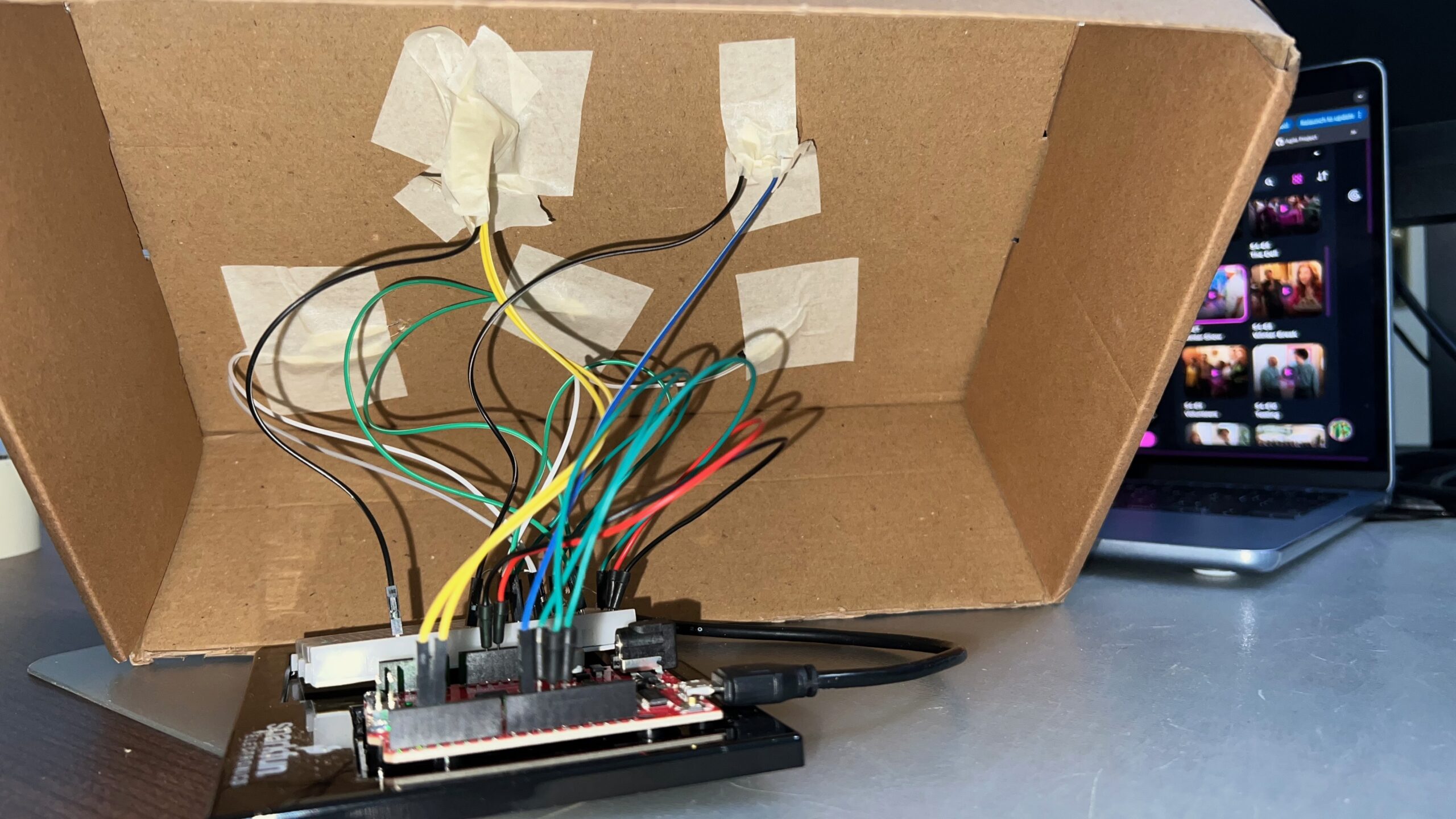
Under the box:

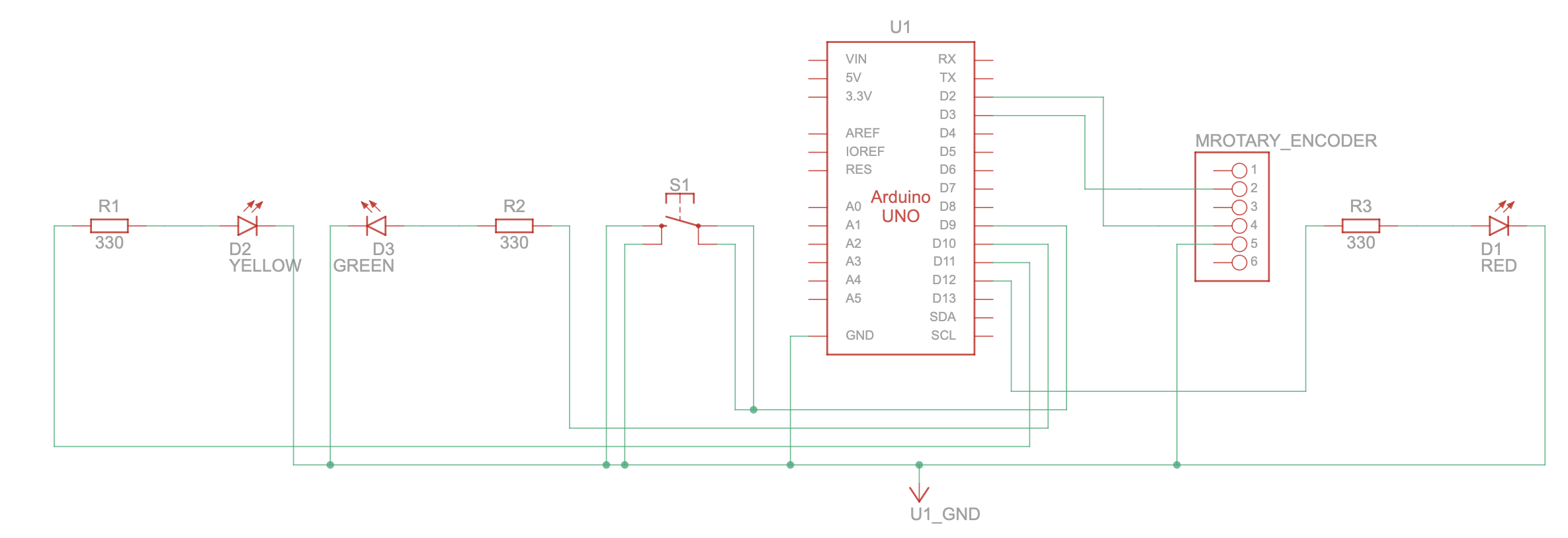
Schematic

Screenshots from the p5 sketch:

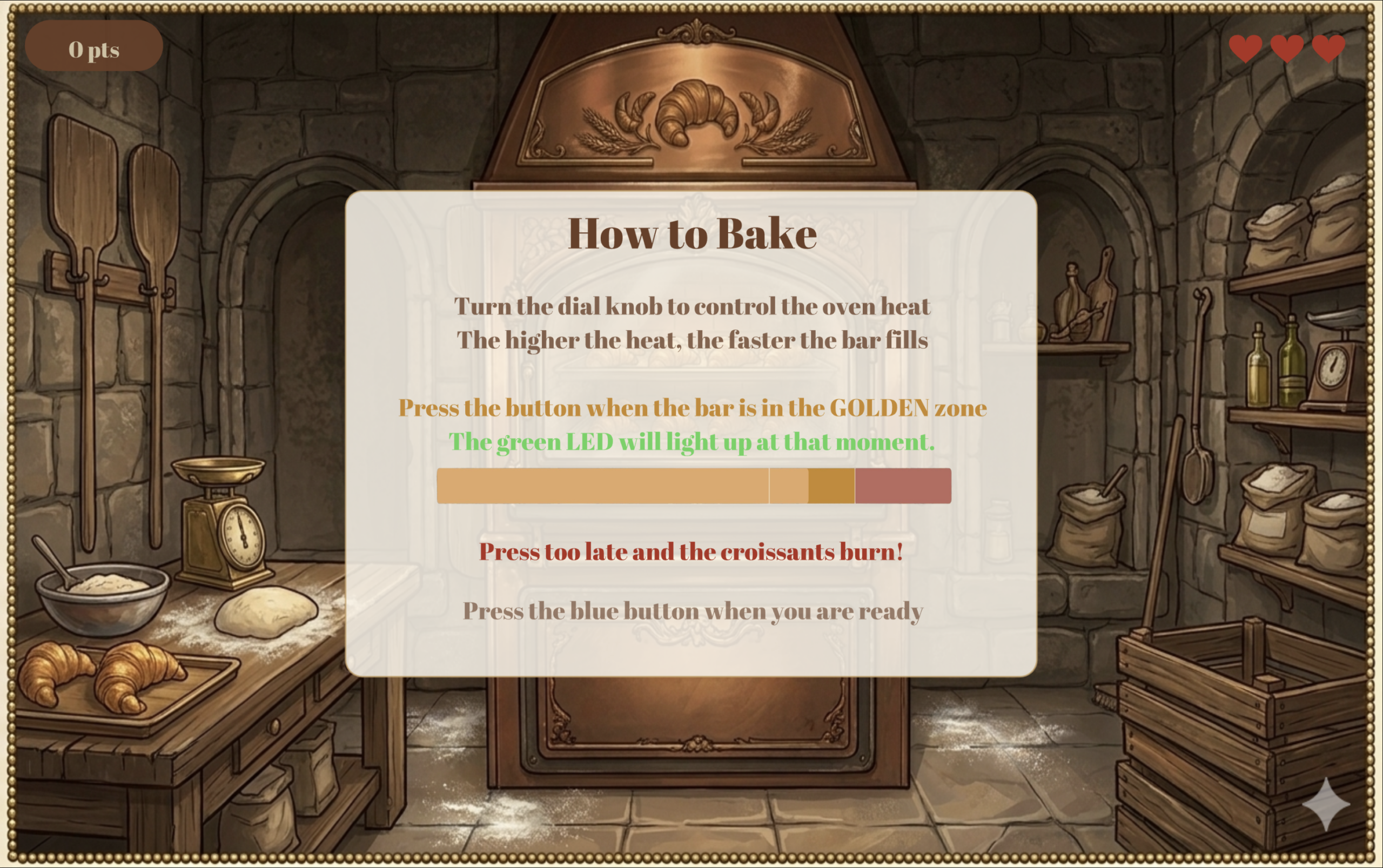
Below is the first screen the user sees after the home screen. It provides instructions for the first part of the game: the baking stage.

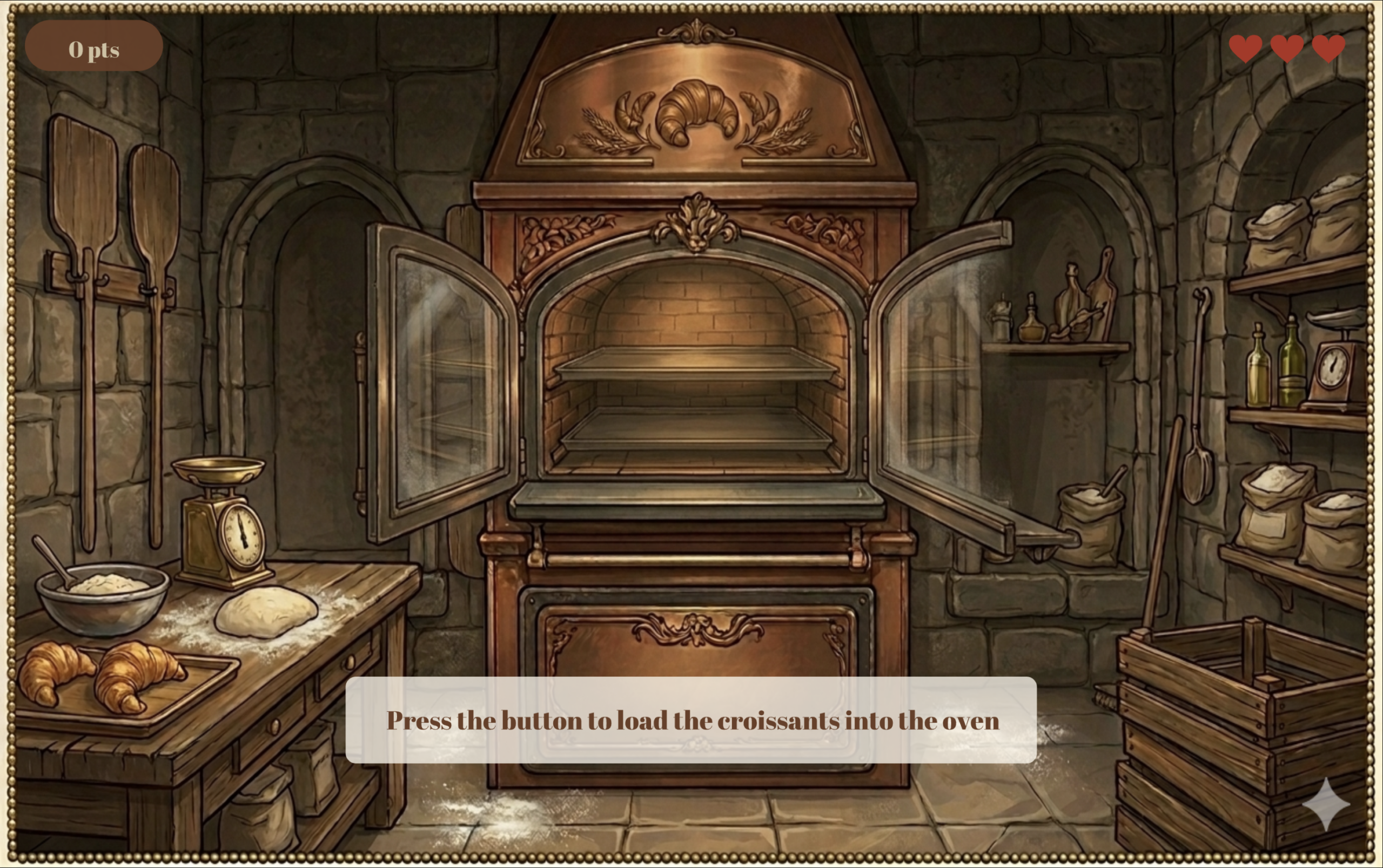
Below is the second screen in the game. The user must click the button on the control panel to load the croissants into the oven.

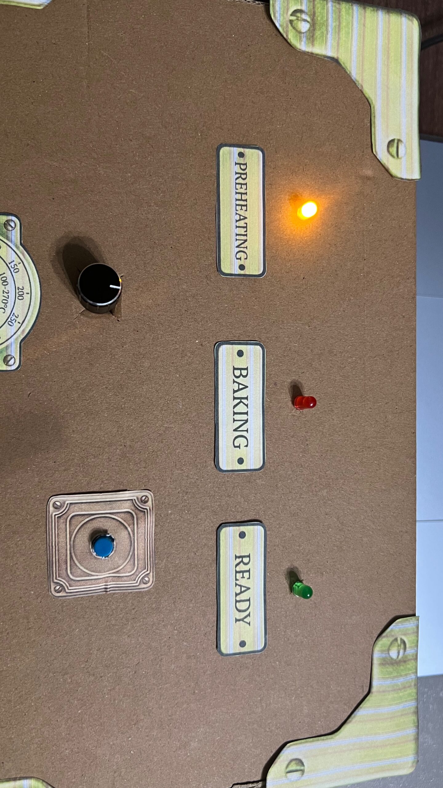
During the loading stage, p5 sends a signal to Arduino to turn on the yellow LED light, signaling the preparation stage.

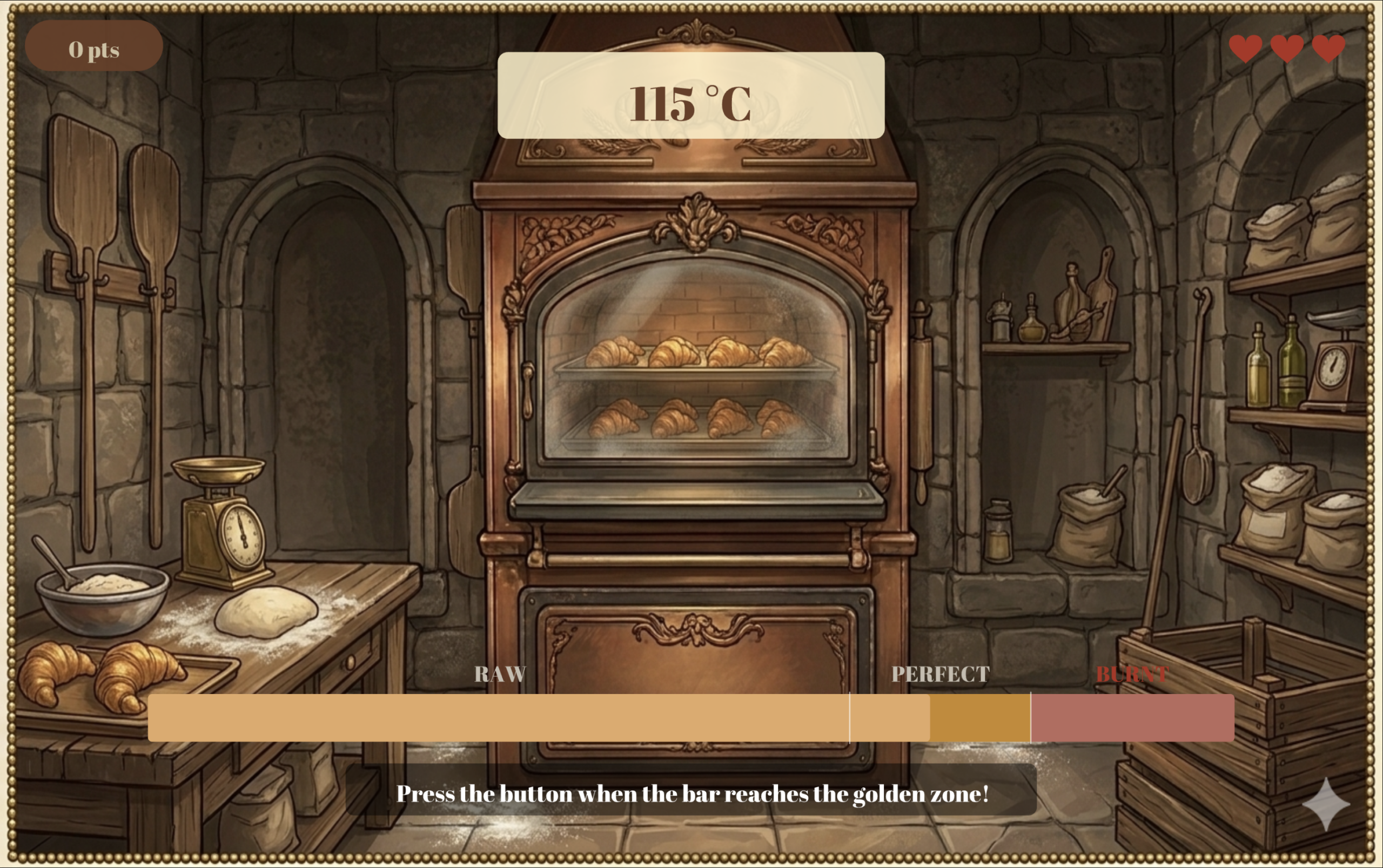
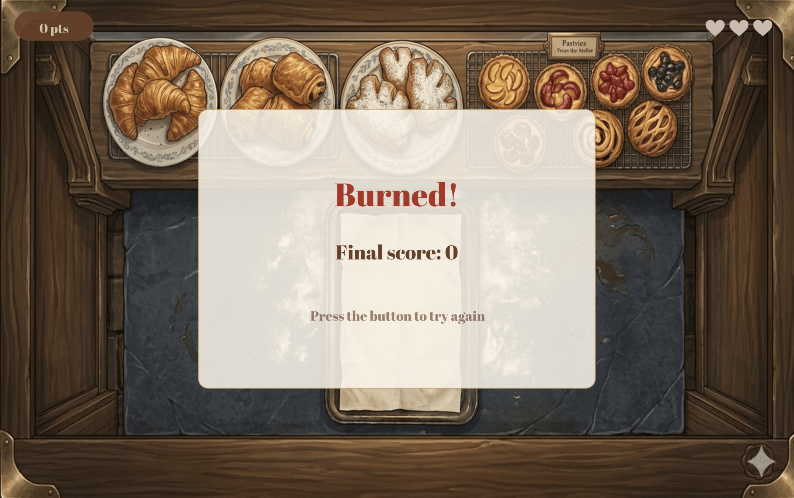
After that, the user controls the speed of the progress bar using the encoder dial. The higher the temperature the faster the bar moves. The user must click the button when the progress bar is in the “Perfect” section to earn full points. Clicking too early makes you lose points, and clicking too late costs you 1 of the 3 lives you get (displayed in the top right corner) and the game takes you back to the screen above to load a new batch of croissants into the oven.

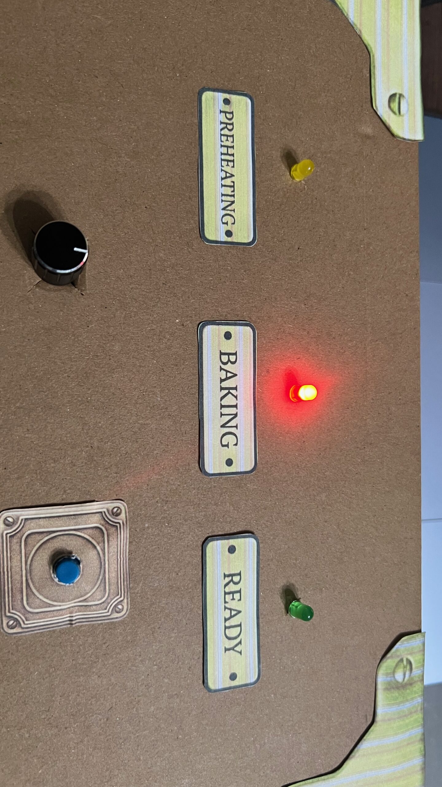
As soon as the player enters the baking stage, and before the progress bar enters the “Perfect” section, p5 send a signal to Arduino to turn on the red LED light, signaling the baking stage.

When the bar enters the “Perfect” zone, p5 send a signal to Arduino to turn on the green LED, indicating the croissants are ready.

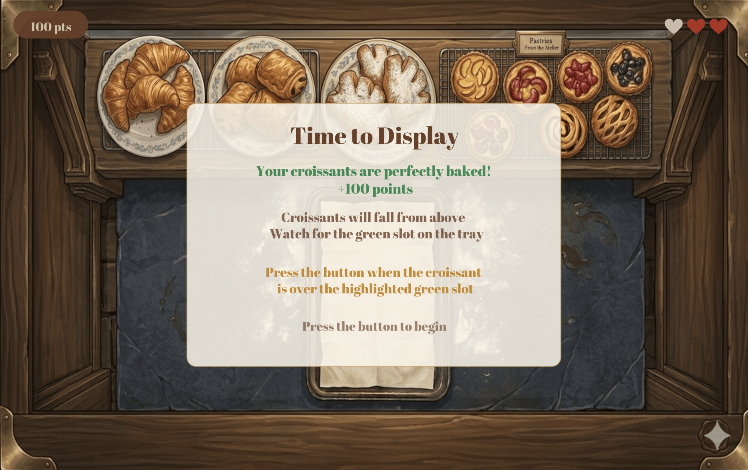
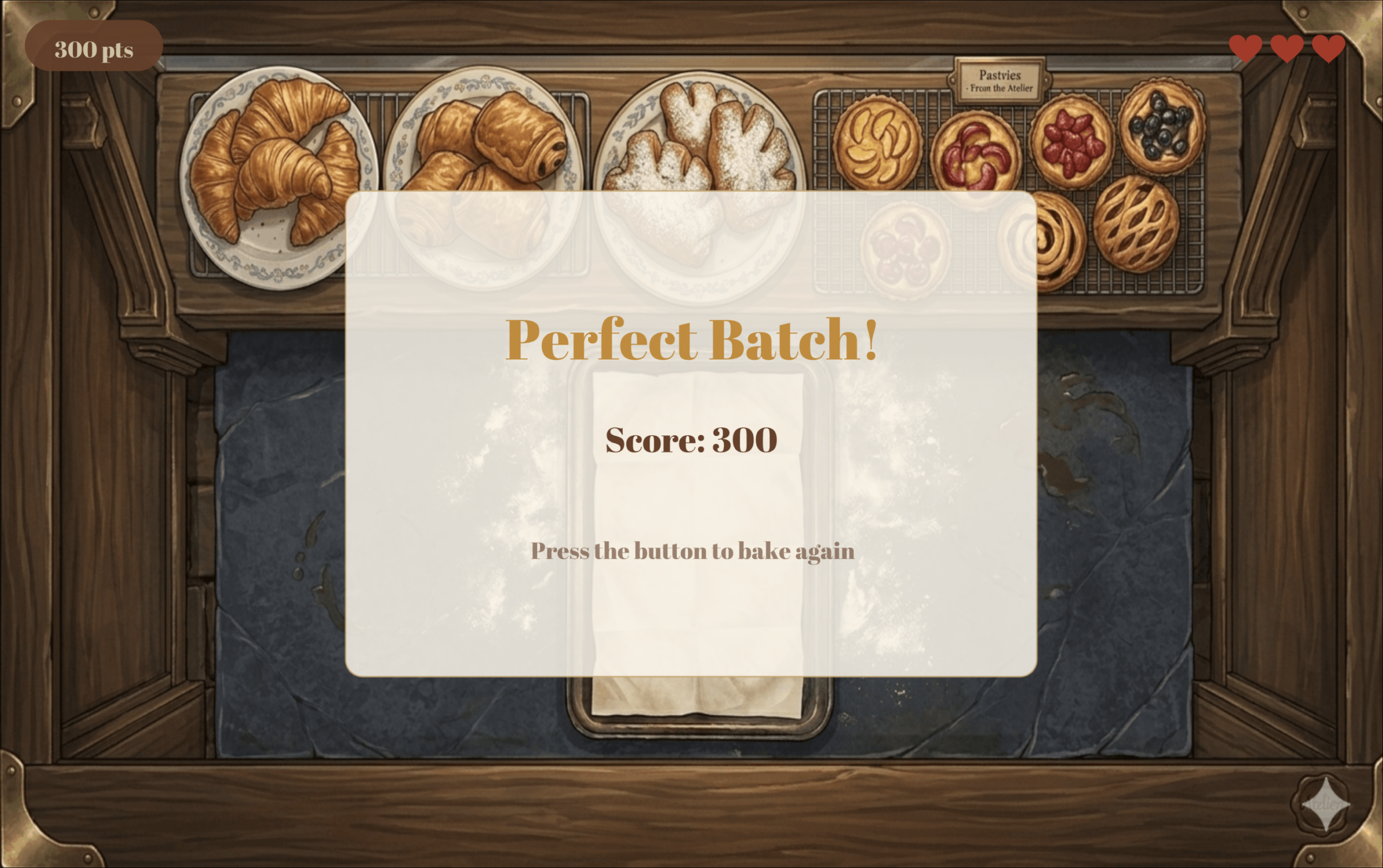
If the user perfectly bakes the croissants, the screen below is displayed, giving the user full points and instructions on how to place the croissants for display.

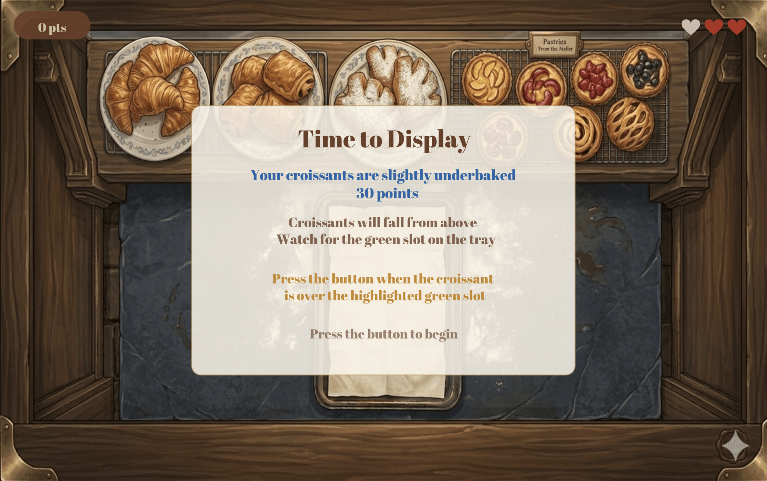
If you underbake the croissants, then you lose 30 points, earning only 70 pts instead of 100. The screen below is displayed informing you of your result and the same instructions above on how to play the second and final stage of the game.

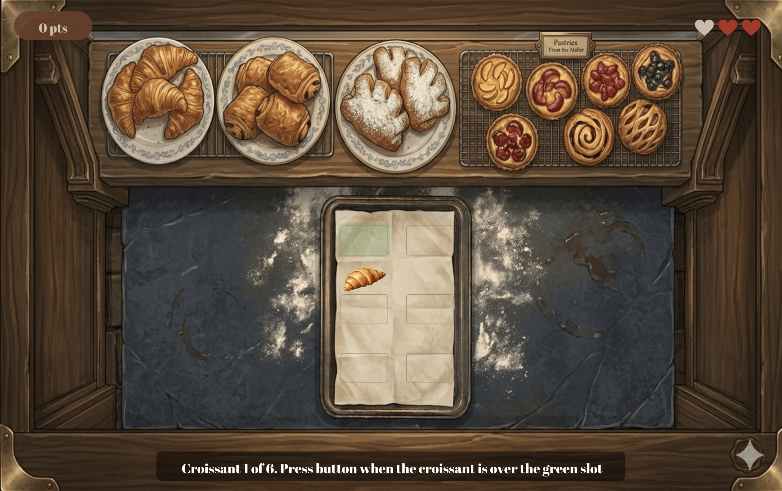
In this stage, you must place 6 croissants in their designated spots on the tray to get them ready for display. The croissant will be falling from the top of the screen, and the user must click the button at the right moment to correctly place the croissants.

Failing to place the croissant correctly costs you a life, and once you lose all 3 lives you have, then the game is over and the game over screen is displayed.

Below is the winning screen.

Description of p5 Code

The code is split across eight JavaScript class files, each responsible for a distinct part of the game.

SerialComm handles all communication between p5.js and the Arduino. Every frame it reads the latest line sent from the Arduino over Web Serial, parses it into an encoder value and a button state, and validates the values before accepting them to filter out any garbage data sent on startup. It also exposes methods for sending single character LED commands back to the Arduino, opening the Chrome port picker, and resetting the encoder counter to zero at the start of each bake.

OvenScene manages everything that happens during the baking phase. It tracks the baking progress, calculates the fill speed based on the encoder value, detects when the golden zone is first reached to trigger the green LED, handles the button press result, plays and stops the timer and ding sounds at the right moments, draws the temperature display pill, and animates smoke particles once the croissants start to burn.

ProgressBar is a standalone class that draws the baking bar at the bottom of the oven scene. It divides the bar into three colour coded zones: blue for raw, gold for the perfect window, and red for burnt, and animates the fill colour shifting from cream to red as the croissants get closer to burning.

FallingCroissant represents a single falling croissant during the display phase. It stores the croissant’s position and fall speed, moves it downward by its speed each frame, checks whether it is within the tolerance zone of its target slot, and detects when it has fallen past the bottom of the tray without being placed.

TrayScene manages the full display stage of the game. It maintains an array of six slots and tracks which ones have been filled, spawns a new falling croissant aimed at the current target slot, checks button presses against the zone detection from FallingCroissant, increases the fall speed slightly after each successful placement to make the game progressively harder, and sends green or yellow LED commands to the Arduino in real time depending on whether the croissant is currently over the target zone.

Header draws the score pill and life hearts that sit on top of every game scene. It uses push() and pop() to isolate its drawing state so that text alignment and rect mode settings from other scenes do not bleed into the header display.

GameManager is the main class which controls the flow of the game. It cycles through nine game states: connect, main menu, baking instructions, oven loading, baking, display instructions, display, win, and game over, drawing the correct background image and calling the correct scene method each frame. It also handles score tracking, life management, screen flash effects, and game resets.

Finally, sketch.js declares all global variables, loads every image, font, and sound file in preload(), initializes the GameManager in setup(), delegates all drawing and logic to it in draw(), and handles the two keyboard shortcuts: `F` to toggle fullscreen and `SPACE` to open the Arduino connection dialog.

Description of Arduino Code

For the encoder, instead of checking its value in the main loop like I originally tried to do with a potentiometer, I used hardware interrupts. This means the Arduino immediately runs the read_encoder function the moment either encoder pin changes, without having to wait for the loop to get to it. This was really important because encoders fire very fast and the loop was simply too slow to catch every click reliably. Inside read_encoder, a lookup table of 16 possible pin state combinations is used to figure out which direction the encoder was turned, and a counter variable goes up or down accordingly. The counter is clamped between 0 and 100 so no matter how much the player spins the dial, the value always stays in a range that p5.js can work with. There is also a fast turning detection built in. If two clicks happen within 0.025 seconds of each other, the counter jumps by 3 instead of 1, making the dial feel more responsive when spun quickly.

For the button, the code detects the exact moment it goes from unpressed to pressed rather than reading it continuously, so holding the button down only counts as one press. This was important for the game because a lot of the interactions are time sensitive and a held button registering multiple times would completely break the logic.

Every 50 milliseconds, the Arduino sends a line to p5.js in the format “counter,buttonState” (for example `75,1` means the dial is at 75 and the button was just pressed). On the other side, p5.js sends back a single character (`Y`, `R`, or `G`) and the `setLED` function turns on the matching LED and turns the other two off. The special character `X` resets the counter back to zero, which happens at the start of every new bake so the player always starts from low heat.

Aspects I am Proud of

Considering the simplicity of my game logic, I wanted to focus my attention on the design, aesthetics, and user-friendliness. Since I usually do not get to be really creative for my coding projects in my CS classes, I wanted to take this opportunity to create something visually appealing.

I spent a lot of time with Gemini asking it to generate the images for the game until it generates exactly what I need. When it failed to do so, I used different scraps it generated for me and designed the exact image I had in mind on Canva. I also spent some time on the audio: finding the audios I need, converting them to mp3, and trimming them to my liking.

Additionally, the most time consuming part of this project was ensuring all the elements and text on the p5 sketch were placed exactly where I needed them and relative to the window size. I spent hours fixing different numbers to get everything exactly where I wanted it to be, running the sketch at least 100 times for sure.

Finally, I wanted to ensure I created a great user experience. I know how frustrating it is when you struggle to understand the logic of a game and how it works; therefore, I wanted to use this project as a chance to practice creating clear instructions with visuals on how to play. I tested my work on my sister by giving her no context on how to play and seeing if she can figure it out only by reading the instructions on the sketch, and she did!

Areas for Improvement

Despite being proud of the final product and its aesthetics, I am actually not the happiest with my concept. I wanted to create a more unique project idea, but was having a bit of a brain fog and could not think of anything. I also would have liked to create a better control box to hold my Arduino components, but I had to work with what I could find around me while keeping ease of use in mind.

References

Arduino:

Images:

Week 14 – Final Project

Concept

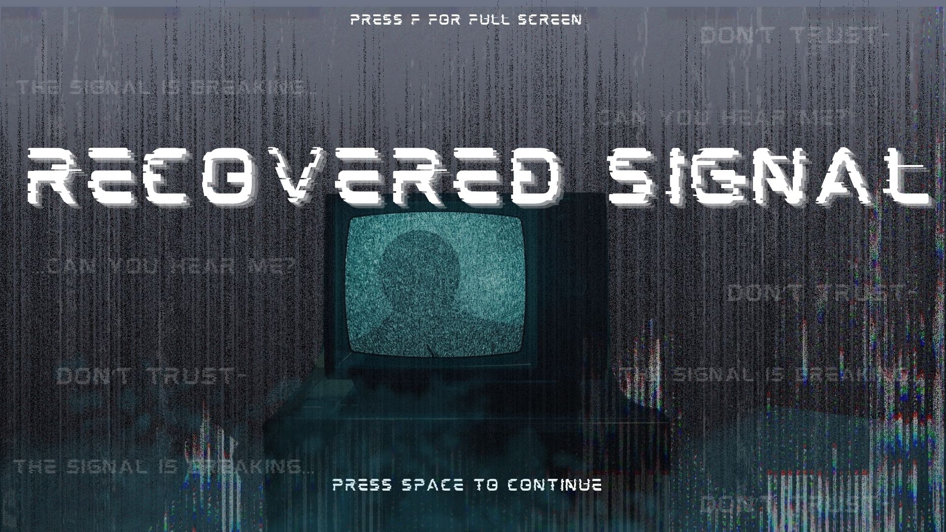
My final project is an interactive rhythm based storytelling game with somewhat of a horror theme. The player presses one of four physical buttons to match falling tiles on the screen, and every correct hit helps restore the signal. As the signal gets stronger, pieces of a hidden story are revealed one fragment at a time, until the final message. I wanted the game to feel like the player was decoding a broken transmission, so the gameplay mixes rhythm, suspense, and storytelling together instead of feeling like a normal rhythm game.

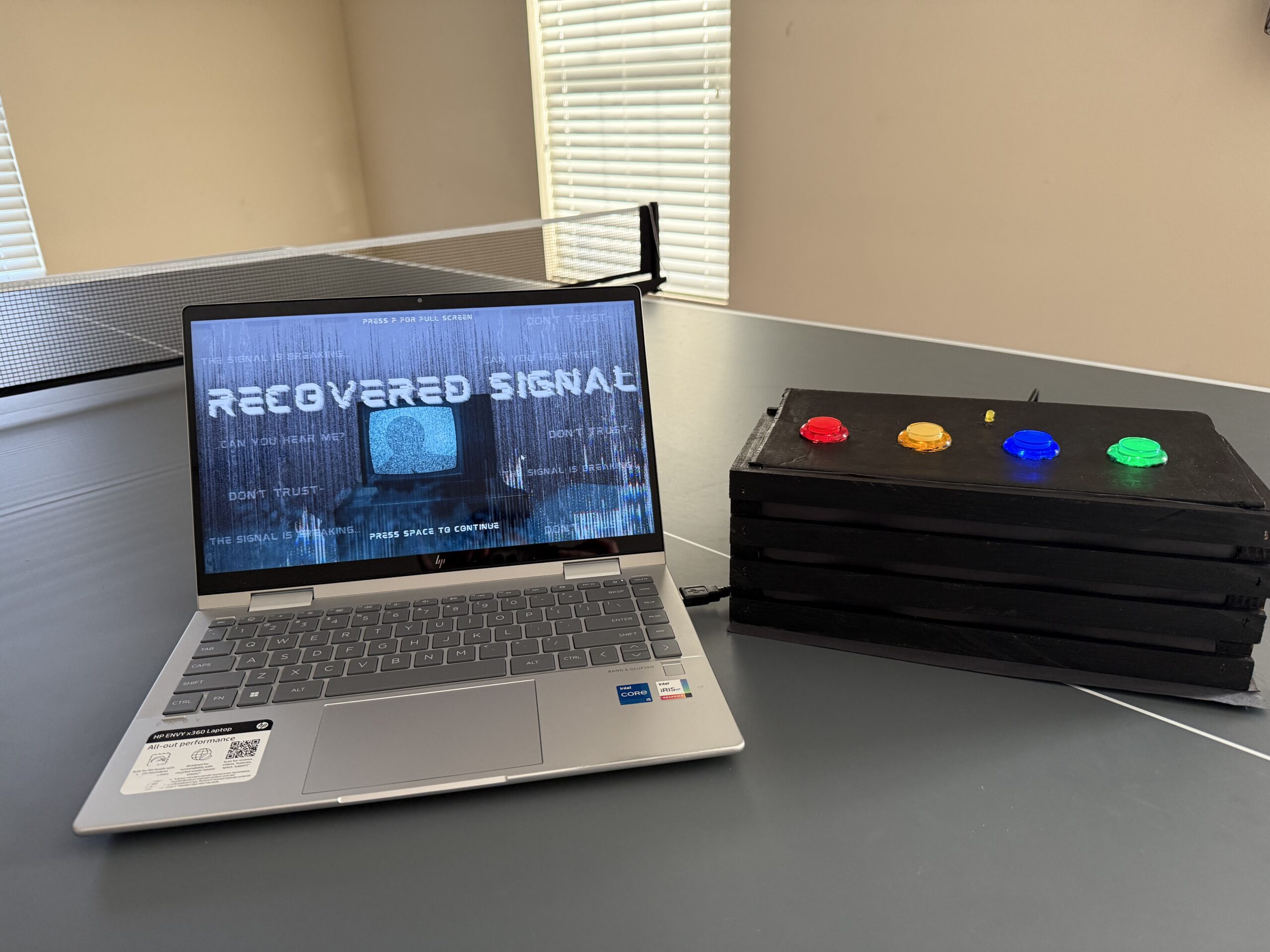
Images

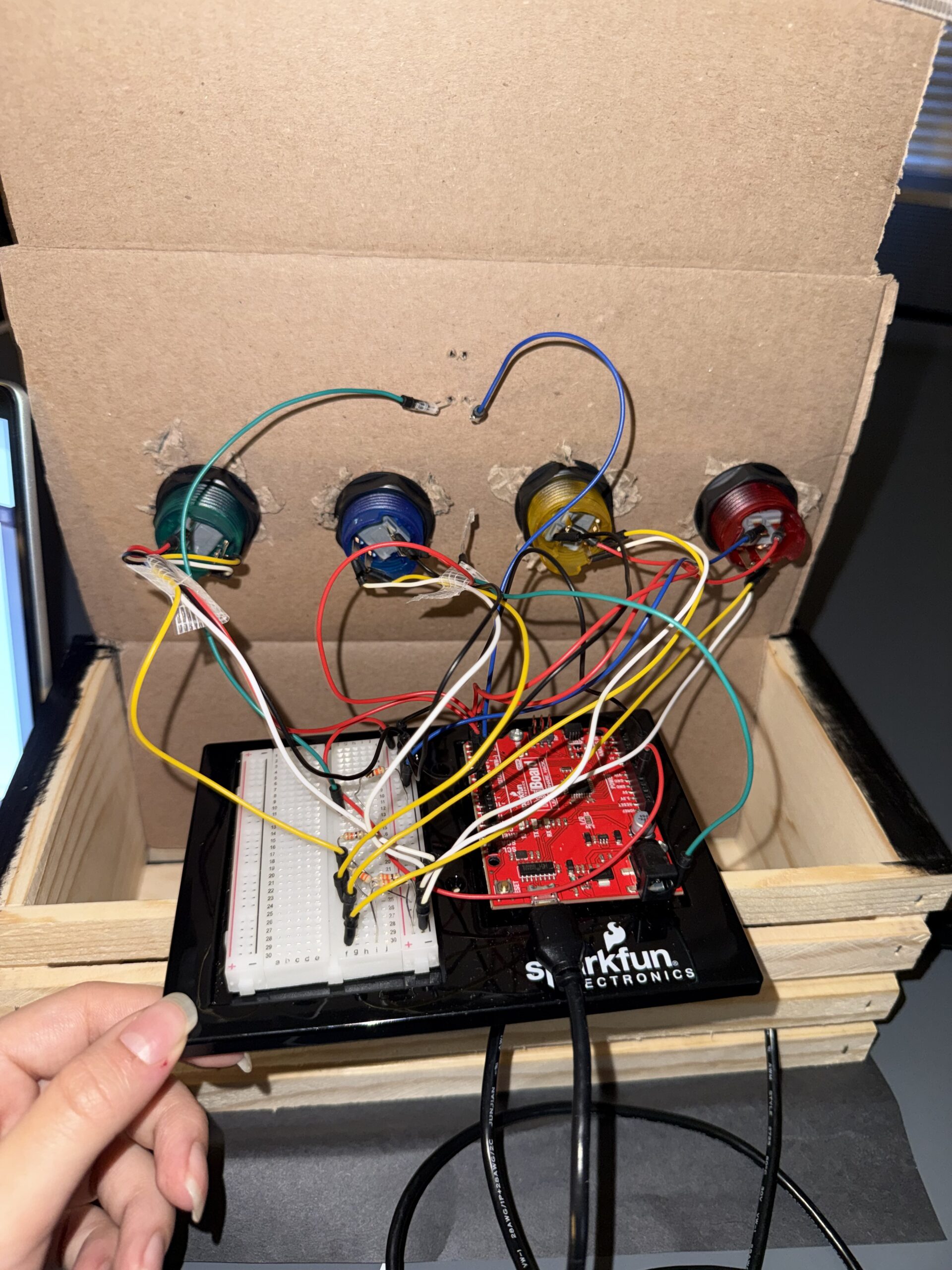
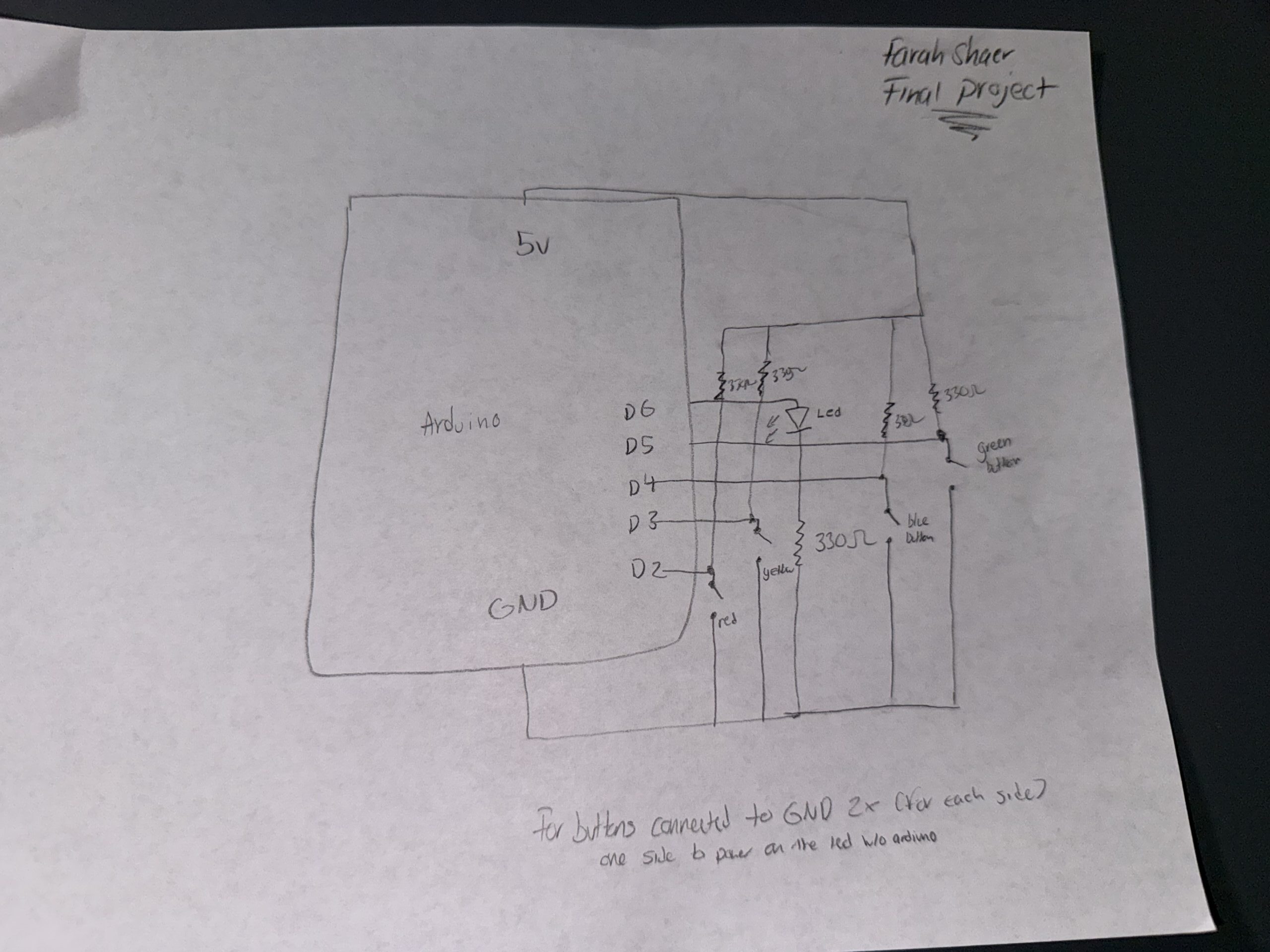
Schematic

User Testing video

Description of interaction design

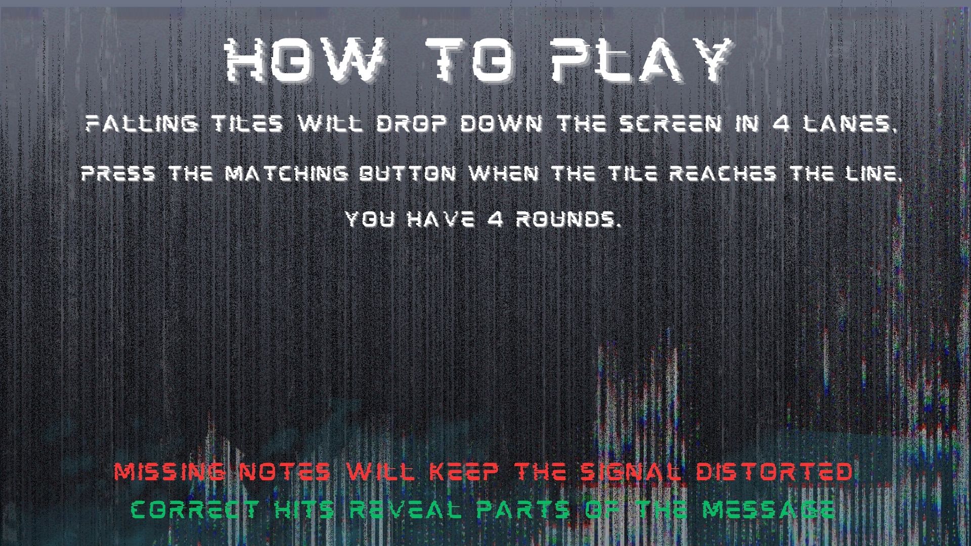
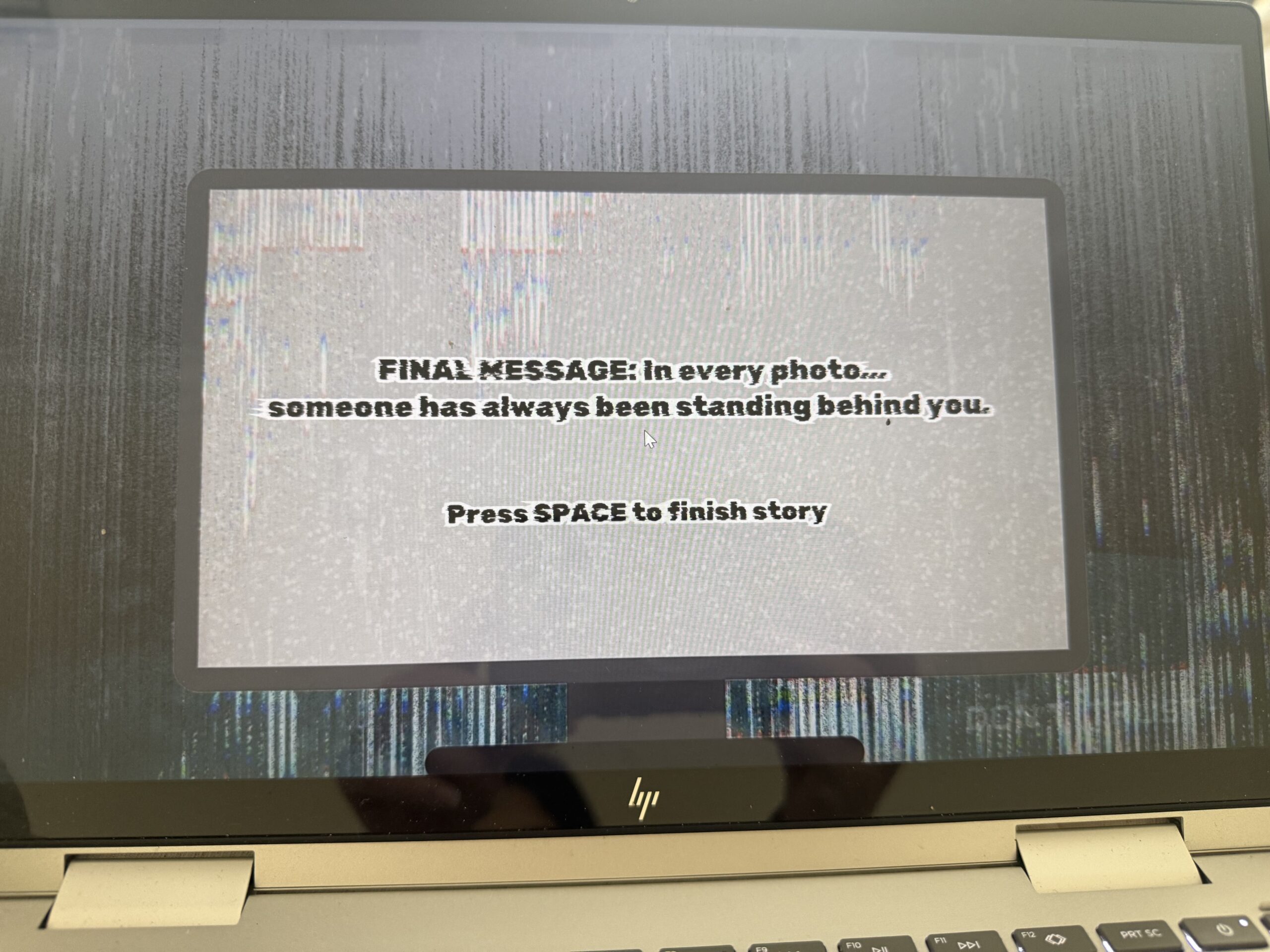
The interaction is based on rhythm timing. Falling tiles move down four lanes, and the player presses one of four buttons that match those lanes and tiles. The player must press the correct button when the tile reaches the hit line near the bottom of the screen. If the timing and button match correctly, the tile counts as a successful hit, the signal bar increases, and the beep sound effect plays. Once the player reaches enough successful hits, the game moves into the “reveal” state, where part of the hidden story is shown on a projector background screen with static sounds and flickering text. After reading the fragment, the player presses space to continue to the next round. This repeats until the final message is revealed.

Description of p5.js code + code snippets + embedded sketch

The p5 code controls almost everything the player sees and experiences visually. At the top of the code, I created variables for the game states, story progress, tiles, spawning system, sounds, images, and serial communication. I also use sentenceProgress to track how many correct hits the player has made and hits needed to decide how many successful hits are required before unlocking the next story fragment. The currentStory variable stores whichever random story is selected for that game session.

One part I spent a lot of time on was the tile spawning system. I used a spawnTimer and spawnInterval to control when new tiles appear. Every frame during gameplay, spawnTimer increases by 1 like a stopwatch. Once it becomes larger than spawnInterval, which I set to 50, the game creates a new tile in a random lane using tiles.push(new Tile(randomLane, -100, 4)). Then the timer resets back to 0 and starts counting again. This makes the tiles appear at steady intervals instead of all at once. I liked this method because it gave me better control over rhythm and difficulty.

The tile checking system works by comparing the button sent from Arduino to the tile’s lane. Arduino sends a number from 1 to 4 depending on which physical button was pressed. In p5, I store that in latestButton. Then inside the game loop, every tile runs tiles[i].checkHit(latestButton). This checks if the tile is close enough to the hit line and whether the correct matching button was pressed. If both are true, the game counts it as a hit, adds 1 to sentenceProgress, resets latestButton back to -1, and plays the tile sound effect. If the tile goes off screen or gets hit, it gets removed from the tiles array using splice(). This keeps the game running smoothly and prevents old tiles from staying on screen.

//check win condition
  if (sentenceProgress >= hitsNeeded && state === "playing") {
    //if player reaches required hits
    state = "reveal";
  }

  //spawn tiles
  if (state === "playing") {
    spawnTimer++; //counts frames and adds 1 like a stop watch 
    if (spawnTimer > spawnInterval) {
      //to check if 50 frames has passed yet
      let randomLane = floor(random(4)); //chooses a random lane (i used floor to round the number down to the nearest whole number since random gives decimal values)
      tiles.push(new Tile(randomLane, -100, 4)); //creates a new faling tile (used push to save it in the tile array so i can do the move and display)
      spawnTimer = 0; //reset timer 
    }

    //update and draw tiles
    for (let i = tiles.length - 1; i >= 0; i--) {
      //start from the last tile and go backwards through every tile in the array (backwards bc I remove tiles)
      tiles[i].move(); //move tile downward
      tiles[i].display(); //draws tile on screen

      //hit check
      if (tiles[i].checkHit(latestButton)) {
        //checks if player pressed correct button at right time
        sentenceProgress += 1; //increaes score
        latestButton = -1; //reset button input
        tileSound.play();
      }
      if (tiles[i].isOffScreen() || tiles[i].hit) {
        //if tile is gone or hit
        tiles.splice(i, 1); //remove tile from array
      }
    }
  }
//hit detection
  checkHit(buttonPressed) {
    let hitZone = height - this.h; //creates the hit line area near bottom of screen (where the player has to press the button)
    if (buttonPressed === this.lane + 1 && //checks correct button, since the lanes start at 0 i added one so it matches
      this.y + this.h > hitZone && //checks if bottom of tile passed into hit zone
      this.y < hitZone + this.h //check if top of tile has not passed too far
    ) {
      this.hit = true; //marks it hit
      return true;
    }
    return false; //wrong button or timing so no
  }
}

I also built a story system using a custom story class (the story and tiles use oop). Each story has an id, title, fragments, final message, and an index to track progress. Instead of writing separate logic for every story, I used an array of story objects so the game can randomly choose one each time it starts. The function getCurrentFragment() shows the current part of the story, next() moves to the next fragment, and isComplete() checks whether the final message should appear. This made the storytelling system much cleaner and easier to scale because I could just add new stories without rewriting game logic.

class Story {
  constructor(id, title, fragments, finalMessage) {
    this.id = id; //so i can identify which story
    this.title = title; //story title
    this.fragments = fragments; //array of the story lines (one by one)
    this.finalMessage = finalMessage; //the last messagge
    this.index = 0; //keeps track of which fragment is shown
  }

  //story navigaton
  getCurrentFragment() {
    //returns the current line of the story based on index
    return this.fragments[this.index]; //takes the current index and give it that specific story line
  }

  next() {
    //moves to the next line in the story
    if (this.index < this.fragments.length - 1) {
      //only move if we are not at the last fragment yet
      this.index++; //increases the index to move to next fragment
      return true; //keep moving forward
    }
    this.index = this.fragments.length; // force completion state
    return false; //if at end do nothing
  }
  isComplete() {
    //check if story is done
    return this.index >= this.fragments.length; //return true if we are at or past the last fragment
  }

  reset() {
    //resets story back to beginning
    this.index = 0;
  }
}

//array that stores all the stories
const stories = [
  new Story(
    1,
    "Emergency Channel 7",
    [
      "If anyone is still receiving this broadcast,\n do not trust the silence outside.\n We thought the signal loss was a storm at first.",

      "Every attempt to trace the interference..\n led back to the same abandoned house.\n No one who entered answered again.",

      "Tonight..\n the signal came through clearly for the first time. \n It wasn't static. It was breathing...\n and it knew all of our names.",
    ],
    "FINAL MESSAGE: Do not attempt to locate the source.\nIt already knows where you are.\nLock the front door."
  ),

Description of Arduino code + code snippets + Github full code

https://github.com/farahshaer/Intro-to-IM/blob/f22e6be49632925d6dba9f548362066ddd89bce8/sketch_may1a.ino 

Arduino handles the physical interaction side of the project. I connected four push buttons as inputs and one LED as an output. Each button represents one lane in the rhythm game. I used input_pullup so the buttons read high normally and low when pressed, which made the wiring simpler because I did not need extra resistors:

void setup() {
  Serial.begin(9600);

  // inputs
  pinMode(redButtonPin, INPUT_PULLUP);//used inputpullup so buttons read high when not pressed and for no resistors
  pinMode(yellowButtonPin, INPUT_PULLUP);
  pinMode(blueButtonPin, INPUT_PULLUP);
  pinMode(greenButtonPin, INPUT_PULLUP);

  // output
  pinMode(signalLedPin, OUTPUT);//LED that reacts to game state
  pinMode(LED_BUILTIN, OUTPUT);//for debugging

In the loop, Arduino constantly checks if any button is pressed. If the red button is pressed, it sends 1 through Serial.println(), yellow sends 2, blue sends 3, and green sends 4. These values are what p5 reads and uses to check player input:

//SEND TO P5 (BUTTON INPUTS 1-4)
  if (digitalRead(redButtonPin) == LOW) {//if button pressed
    buttonPressed = 1;//assign value number
    Serial.println(buttonPressed);//prints value and moves to the next line, send to p5
    delay(100);//delay to prevent repeated button tirggers from one press

  if (digitalRead(yellowButtonPin) == LOW) {
    buttonPressed = 2;
    Serial.println(buttonPressed);
    delay(100);
  }

  if (digitalRead(blueButtonPin) == LOW) {
    buttonPressed = 3;
    Serial.println(buttonPressed);
    delay(100);
  }

  if (digitalRead(greenButtonPin) == LOW) {
    buttonPressed = 4;
    Serial.println(buttonPressed);
    delay(100);
  }
}

Arduino also receives information from p5.js about the current game state. In p5, I created a variable called ledState where start= 0, playing= 1, reveal= 2, and end= 3. This gets sent to Arduino using port.write(). Arduino reads that number using serial.parseInt() and changes the LED behavior depending on the state.

During the game tiles, the LED flickers quickly to feel active and stressful. During the reveal screen, it flickers more slowly to create a static/projector feeling. At the end screen, the LED stays fully on, and during start or instructions, it stays off:

void loop() {
//READ FROM P5
  while (Serial.available()) {//check if p5 is sending data
    digitalWrite(LED_BUILTIN, HIGH);//led on while recieving data
    gameLevel = Serial.parseInt(); //read game state number from p5 (used parseint to skp anything that isnt digits)
    Serial.read(); // clears '\n' after parseint
  }
  digitalWrite(LED_BUILTIN, LOW);

//LED behavior based on game state
if (gameLevel == 1) { //the playing state, faster flicker
  digitalWrite(signalLedPin, HIGH);
  delay(50);
  digitalWrite(signalLedPin, LOW);
  delay(50);
}
else if (gameLevel == 2) {//reveal state, slow flicker for a calmer feel
  digitalWrite(signalLedPin, HIGH);
  delay(200);
  digitalWrite(signalLedPin, LOW);
  delay(200);
}
else if (gameLevel == 3) {//end state, light stays fully on
  digitalWrite(signalLedPin, HIGH);
}
else { //for the start and instruction, led off
  digitalWrite(signalLedPin, LOW);
}

Description of communication between Arduino and p5.js

Arduino sends button presses to p5 so the player can interact with the falling tiles:

//SEND TO P5 (BUTTON INPUTS 1-4)
  if (digitalRead(redButtonPin) == LOW) {//if button pressed
    buttonPressed = 1;//assign value number
    Serial.println(buttonPressed);//prints value and moves to the next line, send to p5
    delay(100);//delay to prevent repeated button tirggers from one press

And p5 reads it and converts it to a number:

//READ FROM ARDUINO HERE
   let data = port.readUntil("\n"); //read message until newline
   if (data && data.length > 0) {
     latestButton = int(trim(data)); //converts input into number 1-4
   }

And then p5 sends game state data back to Arduino so the LED can visually respond to the game:

//SEND TO ARDUNIO HERE (sends game state back)
    let ledState = 0;
    if (state === "start") ledState = 0;
    else if (state === "playing") ledState = 1;
    else if (state === "reveal") ledState = 2;
    else if (state === "end") ledState = 3;
    port.write(ledState + "\n"); //sends the state so ardunio can control LED
  }

Where Arduino reads it and changes the LED state based on the game state:

//READ FROM P5
  while (Serial.available()) {//check if p5 is sending data
    digitalWrite(LED_BUILTIN, HIGH);//led on while recieving data
    gameLevel = Serial.parseInt(); //read game state number from p5 (used parseint to skp anything that isnt digits)
    Serial.read(); // clears '\n' after parseint
  }
  digitalWrite(LED_BUILTIN, LOW);

//LED behavior based on game state
if (gameLevel == 1) { //the playing state, faster flicker
  digitalWrite(signalLedPin, HIGH);
  delay(50);
  digitalWrite(signalLedPin, LOW);
  delay(50);
}

So overall, Arduino sends button input to p5 so the player can interact with the game, and p5 sends game state information back so Arduino can physically respond through the LED.

Aspects of the project that I am particularly proud of

One thing I am particularly proud of is how the concept feels cohesive instead of looking like separate parts forced together. The horror story, the rhythm gameplay, the static visuals the sound design, and the led feedback all support the same theme of restoring a broken transmission. I did not want it to feel like just a button game, so I focused a lot on atmosphere. I am also proud of the story system because it made the game replayable by randomly choosing different types of stories instead of showing the same one every time.

Also, the integration between physical buttons and the tiles, I am really proud of the mapping.

Challenges faced

A big challenge was debugging the story progression and the final reveal logic. At one point, the game would skip the final message and go straight to the ending screen, which broke the whole experience. I had to keep testing how currentStory.next() and currentStory.isComplete() interacted and realized the order of those checks mattered a lot in the kepressed logic:

else if (state === "reveal" && key === " ") {
  //if already showing final message, go to end screen
  if (currentStory.isComplete()) {
    state = "end";
    return;
  }
  //otherwise move to next fragment
  currentStory.next();//move to next line/fragment of story 
  sentenceProgress = 0;//reset player progress for next round 
  tiles = [];//remove all the falling tiles 
  spawnTimer = 0;//reset tile spawn timing 
  hitsNeeded += 2;//increase diffiuclty each round
  state = "playing";//go back to gamestate
}
  if (state === "end" && key === " ") {
    resetGame();
  }
  //serial connect
  if (key === "v") {
    setupSerial();
  }
}

I also had a challenge with the tiles spawning too fast, so I used spawntimer and the spawninterval system, which worked very well.

Future Improvement

If I had more time, I would improve the game by making the difficulty scale smoother and adding visual feedback for missed notes, not just successful ones. Right now I just wanted to focus mainly on correct hits, but stronger fail states would make the tension higher. I would also like to make the LED system more by using multiple LEDs so each story state feels even more immersive. Another future improvement would be adding more story branches where player performance changes, which ending they get, instead of always leading to one final message. I think that would make the game feel even more interactive and personal.

Resources and AI usage

I searched up on google how to shift something and it said use translate(), so i looked at the p5 reference page for more information so I can do it for the tiles and glitch effect: https://p5js.org/reference/p5/translate/

I needed a refresher on return because I wanted to use it to return the current fragment back into the array or to return true/false so the game knows if the story can keep moving forward. so I watched this youtube video:
https://www.youtube.com/watch?v=qRnUBiTJ66Y

Search on google how I can remove a tile from array after it gets off of screen and I found splice, where I then look at the p5 reference page for more information on how to use it: https://p5js.org/reference/p5/splice/

My music would overlap so I looked through the p5 soundfile page to see if there was a fix for that, which I found playmode to help me.
https://p5js.org/reference/p5.sound/p5.SoundFile/

I also wanted to know how to create a line (the one one at the bottom), so I used beginshape() and end (shape) for the to create a continuous wave line. I also used it to understand vertex shapes function in p5 because I did need a refresher:
https://p5js.org/reference/p5/beginShape/

I also used drawingconext reference page for my effects by looking at their examples:
https://p5js.org/reference/p5/drawingContext/

For the tiles:
https://p5js.org/reference/p5/floor/#:~:text=Reference%20floor()-,floor(),the%20value%20of%20a%20number.

AI usage:

I had trouble with the tiles being skipped, so I asked ChatGPT for debugging, and it was because it was looped forward. So I learned that I need to loop it backwards and start from the last tile and go backwards through every tile in the array because I remove tiles, and so it will not mess up with the remaining index. And scanning a list from bottom to top is better so deleting items basically does not confuse the order. for (let i = tiles.length – 1; i >= 0; i–)

My audio and images would not load, so I asked ChatGPT for debugging, and it was because I had them organized in a folder and forgot to call it…

I also wanted a stronger jitter and glitch effect for my falling tiles to make the game feel more unstable and distorted. I was already using sin() for the pulse effect, but I wanted the tiles to feel less smooth and more corrupted. I asked ChatGPT for ideas on how to make the movement feel more random and glitchy, which helped me understand that I could use random values for variation. I then used this.corruption = random(0, 1); and multiplied it with the pulse and jitter movement, so each tile had a slightly different glitch effect that matched the horror atmosphere I wanted

Final Project: Tiny Trails

My Concept

My project is an interactive maze game where the player controls Minnie Mouse using two physical potentiometers connected to an Arduino. The goal is to guide Minnie through the maze, collect all the items (cheese, stars, and hearts), and finally reach Mickey Mouse at the top of the maze. The game also uses LEDs to provide physical feedback: green for winning, yellow for collecting items, and red for hitting a wall. I chose this idea because I wanted to create something a game based on characters I love, so I picked minnie mouse and mickey.

Images and Videos of the project

Images of my project:

Video of my project:


Circuit

Schematic

My schematic includes:

  • Two potentiometers connected to A0 and A1.
  • Three LEDs connected to digital pins 9, 10, and 11.
  • 330 ohms resistors for each LED.
  • Shared ground and 5V rails.

User Testing Video


The steps in my game

Start screen:

Instructions screen: 

Maze game:

After collecting the collectibles:

After reaching Mickey Mouse (The End):

How the Implementation Works

  • Interaction Design:

The player interacts with the game using two physical knobs. One knob controls Minnie’s horizontal movement, and the other controls her vertical movement. The LEDs provide real‑time feedback such as yellow when an item is collected, red when Minnie hits a wall, and green when the player wins. Mickey only appears after all items are collected, and then the player has to go to Mickey to finish the maze to give the player a reward feeling at the end. 

  • Arduino Code Explanation:

The Arduino code reads the two potentiometer values and sends them to p5.js so the game can move Minnie inside the maze. At the same time, the Arduino listens for messages coming from p5.js. These messages contain the number of the LED pin that should blink when something happens in the game, such as collecting an item, hitting a wall, or winning. The Arduino then blinks the correct LED several times to give physical feedback to the player. This creates a simple but effective communication loop between the hardware and the game.

  • Arduino Code Snippet:
// read the two potentiometers
int val1 = analogRead(A0);   // read first potentiometer from A0
int val2 = analogRead(A1);   // read second potentiometer from A1

// send both values to p5.js in one line
Serial.print(val1);          // send first number
Serial.print(",");           // comma so p5.js can split the values
Serial.println(val2);        // send second number and end the line
  • Arduino Github link: 

https://github.com/mhraalnuaimi/arduino-maze/blob/main/tiny_trails.ino 

  • p5.js Code Explanation:

p5.js receives the two values sent from the Arduino and uses them to update Minnie’s position inside the maze. Each value is mapped to the correct x‑ and y‑coordinates so her movement matches how far the player turns each potentiometer. After moving Minnie, the game checks for collisions with walls, collectable items, and Mickey to decide what should happen next. When an event occurs, p5.js sends a pin number back to the Arduino so the correct LED can blink, creating a simple and responsive connection between the physical hardware and the digital game.

  • P5 snippet:
let data = port.readUntil("\n");  // reads one full line of data sent from the Arduino
let fromArduino = split(trim(data), ","); // splits the line into two separate values (x and y)
let xVal = int(fromArduino[0]); // converts the first value from a string into an integer for horizontal movement
let yVal = int(fromArduino[1]); // converts the second value from a string into an integer for vertical movement
let posX = map(xVal, 3, 1020, mazeLeft, mazeLeft + mazeImage.width); // maps the x value to a position inside the maze area
let posY = map(yVal, 3, 1020, mazeTop, mazeTop + mazeImage.height); // maps the y value to a position inside the maze area
minnie.move(posX, posY); // moves Minnie to the new mapped position on the screen
  • P5 sketch embedded:


Used another account because the p5 I was using got throughout the semester got full.

Communication Between Arduino and p5.js:
Communication between the Arduino and p5.js happens in a simple two‑way loop. The Arduino sends two numbers from the potentiometers, and p5.js uses these numbers to move Minnie inside the maze. At the same time, p5.js sends a pin number back to the Arduino whenever something important happens in the game, like collecting one of the icons, hitting a wall, or winning. The Arduino reads this pin number and turns on the matching LED whether it was the green one for winning or yellow one for picking a collectible and red for touching any of the walls. This creates a basic but effective interaction where the hardware and the game respond to each other in real time.

Aspects I’m Proud of
I am proud of several parts of this project. The collision detection where it checks if minnie’s position overlaps with another object in the maze that includes the wall, the collectibles and mickey. I really liked that the LED sends feedback back to the player in order to show them what color is being lit up. The maze also scales well on different screen sizes, which makes the game easy to play on any device that can connect with the Arduino. During user testing, my sister understood the interaction very quickly, which showed me that the design is clear and easy to work with. Overall, I am really proud of this project because the game turned out better than expected.

Challenges Faced and How I Overcame Them
One of the first challenges I faced was with the potentiometers. The ones I ordered from Amazon were loose and unreliable, which made the game go on and off. I tried using the small Arduino potentiometers because they worked better, but they were too tiny and uncomfortable to turn. In the end, I had to order new potentiometers at the last minute, and those finally gave me smooth and stable control. Another issue was that my game wasn’t working at all at one point, Minnie was jumping all over the maze in random directions. I thought the problem was in my code, but it turned out to be a wiring mistake. The connection from the breadboard to the 5V pin was missing, so the potentiometers were sending unstable values. Fixing that single wire immediately stabilized the movement. I also ran into a major coding problem where a missing bracket caused an “unexpected end of input” error in p5. I solved this by checking each function and making sure every opening brace had a matching closing brace. Another challenge was getting the maze to scale correctly on different screen sizes. At first, the maze stretched or got cut off depending on the device. To fix this, I used Ai to calculate the two scale values: one based on the screen width and one based on the screen height. Then I chose the smaller of the two so the maze would always fit fully on the screen. This made the game look better and scaled proportionally no matter what device it was played on.

Areas for Future Improvement

There are several areas I would like to improve in the future. I want to add multiple levels of the maze, and more sound effects for reaching the different levels. I would also like to add a timer for the harder levels. Another idea is to add more physical feedback, such as additional LEDs for reaching the next level in another color other than green, yellow, or red.

Stipend Spend:

Blue Arduino Potentiometers: https://www.amazon.ae/dp/B07S69443J?ref_=pe_144460031_1285786251_i_fed_asin_title
Potentiometers: https://www.amazon.ae/dp/B0D4LKPLDT?ref_=pe_144460031_1285786251_i_fed_asin_title
Cardboard:
https://www.amazon.ae/dp/B0BWJS8W2M?ref_=pe_144460031_1285786251_i_fed_asin_title
Jumper wires: https://www.amazon.ae/dp/B0F3XDBQYX?ref_=pe_192358311_1415951701_t_fed_asin_title
Potentiometers kit (The ones I used for my arduino): https://www.amazon.ae/dp/B07ZKK6T8S?ref_=pe_151259381_1319653131_t_fed_asin_title&th=1

Citations
1. Item Pickup Sound
URL: https://opengameart.org/content/item-sfx
How I used it: I used this sound effect to play a small “pickup” noise whenever Minnie collects a cheese, star, or heart in the game.

2. Winning Sound
URL: https://freesound.org/people/Mihacappy/sounds/844146/
How I used it: I used this audio clip as the victory sound that plays when the player reaches Mickey after collecting all items.

3. Bump Sound
URL: https://pixabay.com/sound-effects/film-special-effects-retro-game-sfx-jump-bumpwav-14853/
How I used it: I used this bump sound to alert the player whenever Minnie touches a wall in the maze.

4. Majestic Rag (1914): Ben Rawls & Royal Neel (Wikimedia Commons)
URL: https://commons.wikimedia.org/wiki/File:%22Majestic_Rag%22_(1914),_by_Ben_Rawls_and_Royal_Neel.oga
How I used it: I used this music as the looping background soundtrack to give the game a fun and playful type of atmosphere.

5. Nerko One Font: Designed by Nermin Kahrimanovic (Google Fonts)
URL: https://fonts.google.com/specimen/Nerko+One?query=cute&categoryFilters=Feeling:%2FExpressive%2FPlayful&preview.script=Latn
How I used it: I used this font for the text on the instructions page to match the aesthetic of the Minnie‑themed design.

6. p5.js Image Resize Documentation
URL: https://p5js.org/reference/p5.Image/resize/ 
How I used it: I used this documentation to correctly resize images in the game so they scale proportionally on different screen sizes.

Ai usage: 

ChatGPT helped me by explaining the math I needed to make the maze image automatically resize so it fits the screen without stretching or getting cut off. It showed me that I had to compare the maze’s size to the screen’s size and then choose the smaller scale so the whole maze stays visible. I used this explanation to write the final scaling code in my game.

Here is the snippet:

let scaleW = width / mazeImg.width;
let scaleH = height / mazeImg.height;
let scale = min(scaleW, scaleH);

mazeImg.resize(mazeImg.width * scale, mazeImg.height * scale);

This code checks how big the maze image is compared to the screen.

  • scaleW is how much the image needs to shrink to fit the width.
  • scaleH is how much the image needs to shrink to fit the height.
  • min(scaleW, scaleH) picks the smaller number so the whole maze fits without getting cut off.

Then the image is resized using that scale so it always fits perfectly on the screen without being cut off or too stretched.

ChatGPT also helped me by generating several images that I used in the game. These include the game title “Tiny Trails,” the Start button, the Arduino Connect button, the Instructions button, the Back button, and the How to Play title on the instructions page. It also generated the maze image, the characters Minnie Mouse and Mickey Mouse, and the collectable icons: the cheese, the heart, and the star. In addition, ChatGPT created The End title and both background images used on the start page and the maze page. I also used Ai to help generate the image of the bow I printed for my physical box I made and the polka dot pattern as well.