
Exercise 1:
Demo:
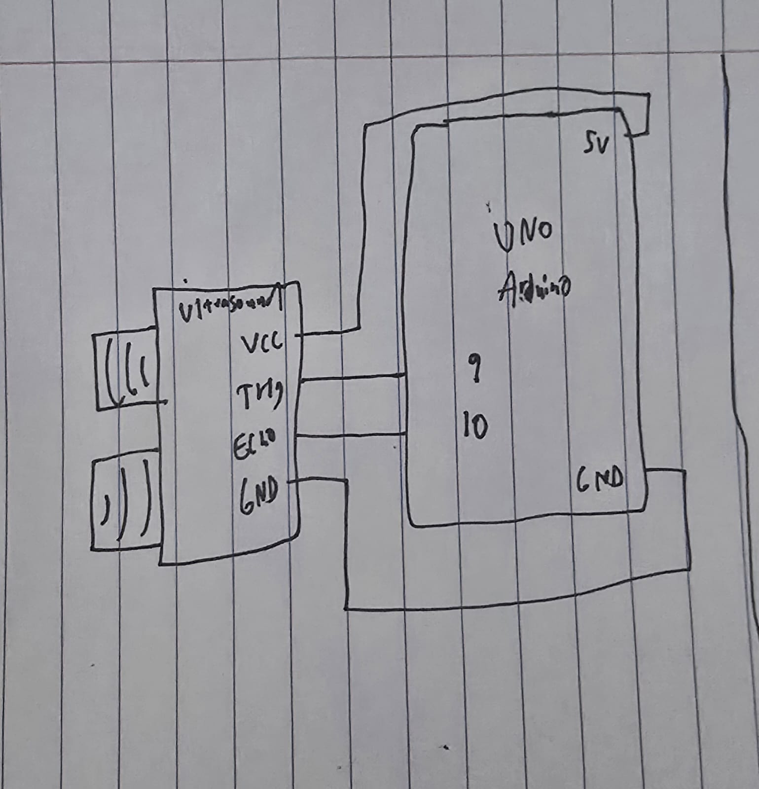
Schematic:
Implementation:
I used an ultrasound sensor for this exercise, so the ellipse moves depending on how close or far my hand is from the sensor.
void loop() {
  // Trigger the sensor
  digitalWrite(trigPin, LOW);
  delayMicroseconds(2);
  digitalWrite(trigPin, HIGH);
  delayMicroseconds(10);
  digitalWrite(trigPin, LOW);

  // Measure the bounce back time
  long duration = pulseIn(echoPin, HIGH);

  // Calculate distance
  int distance = duration * 0.034 / 2;

  // Send just the number to p5.js
  Serial.println(distance);

  delay(50);
}
The code for using the sensor is pretty standard, trigger it so often, measure the duration using the formula (speed * time), and then send that to p5js.
Speed is the speed of sound (0.034 cm per microsecond) and time is duration / 2 since it is a round trip.
// Read from serial
    let str = port.readUntil("\n");
    if (str.length > 0) {
      let val = int(str);
      // Validate value
      if (!isNaN(val)) {
        sensorValue = val;
      }
    }


    // Map the value
    let xPos = map(sensorValue, 5, 50, 0, width);
    // Constrain the ellipse to canvas
    xPos = constrain(xPos, 0, width);

    fill(0, 255, 200);
    noStroke();
    ellipse(xPos, height / 2, 50, 50);
From p5js side, we take the value, validate it, then create a mapping of the value to x position as well as constraining it, then finally draw the ellipse.
Exercise 2:
Demo:
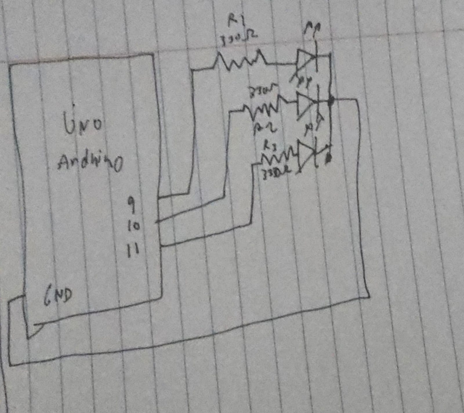
Schematic:
Implementation:
In p5js, I have 3 sliders, 1 for R, 1 for G, and 1 for B, I am using an RGB LED, so we can switch around the sliders to get our custom color from the LED.
// Read the three integers sent from p5.js
// parseInt() looks for digits and skips non-digits
int r = Serial.parseInt();
int g = Serial.parseInt();
int b = Serial.parseInt();

// Look for the newline character to confirm the end of the message
if (Serial.read() == '\n') {
  // Apply the brightness to each pin
  analogWrite(redPin, r);
  analogWrite(greenPin, g);
  analogWrite(bluePin, b);
On the Arduino side the code is pretty simple, just read each color and write it to the LED.
// Send to Arduino
port.write(r + "," + g + "," + b + "\n");
This is really what’s doing the work, it takes the values from the slider and sends them to the Arduino in such a format that it could read it easily.
Exercise 3:
Demo:
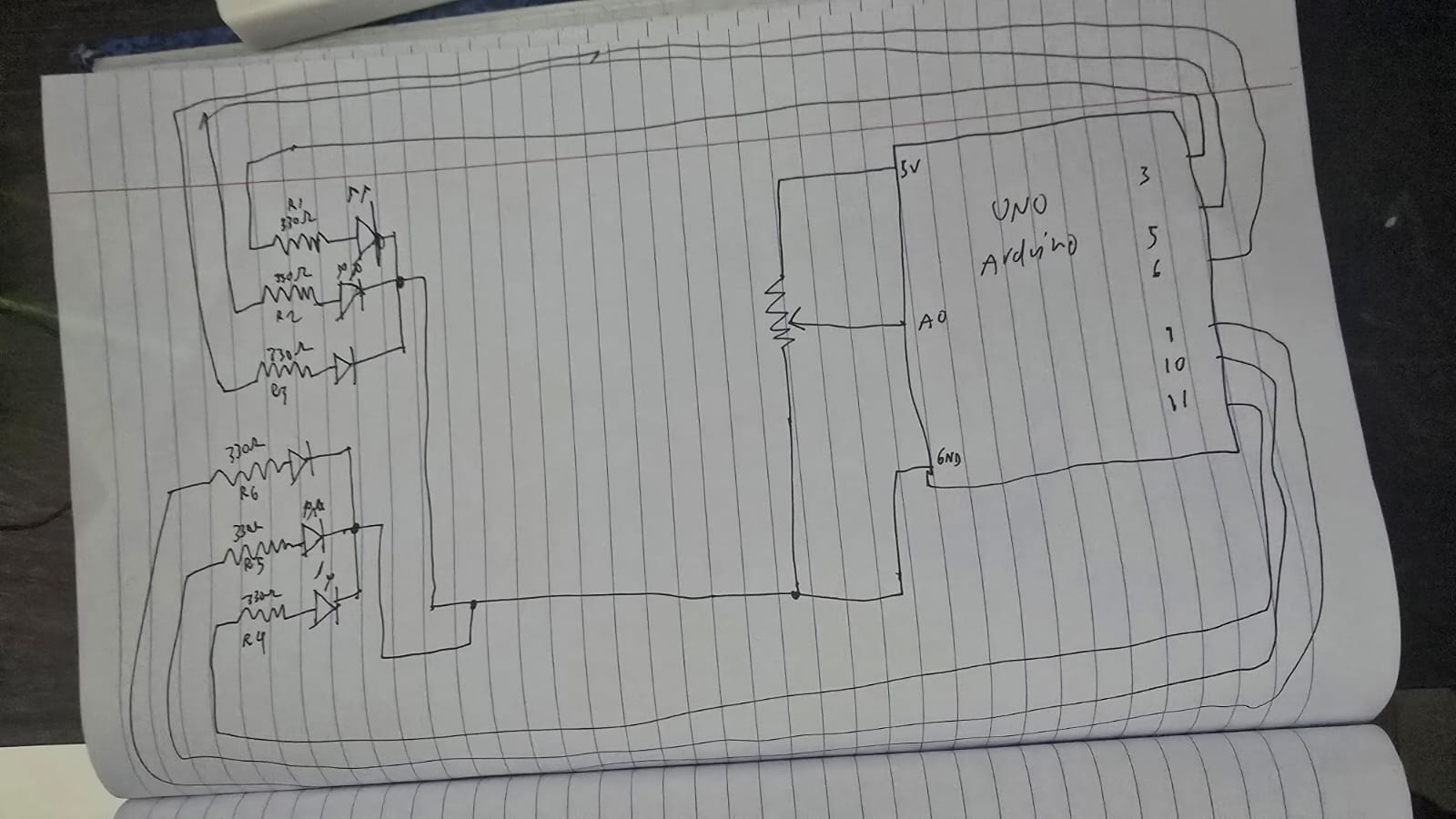
Schematic:
Implementation:
I copied the basic implementation of the wind mechanics from the code, however instead of left and right buttons, I switched out with a potentiometer:
let windForce = map(sensorValue, 0, 1023, -0.5, 0.5);
I have 2 RGB LED’s, and each light up depending on what side of the “wall” the ball hits.
// Left Wall
if (position.x < mass/2) {
velocity.x *= -0.9;
position.x = mass/2;
sendColor("L");
}
// Right Wall
if (position.x > width - mass/2) {
velocity.x *= -0.9;
position.x = width - mass/2;
sendColor("R");
}
The code to send the colors itself to the Arduino is:
// Sending color + direction
function sendColor(side) {
  if (port.opened()) {
    let r = floor(random(255));
    let g = floor(random(255));
    let b = floor(random(255));
    // Sending: Side,R,G,B (e.g., "L,255,0,0")
    port.write(side + "," + r + "," + g + "," + b + "\n");
  }
}
We create a random number for each color and then send it to the Arduino along with the direction.
if (side == 'L' || side == 'R') {
  Serial.read(); // Skip the comma
  int r = Serial.parseInt();
  int g = Serial.parseInt();
  int b = Serial.parseInt();

  if (side == 'L') {
    flash(L_red, L_green, L_blue, r, g, b);
  } else {
    flash(R_red, R_green, R_blue, r, g, b);
  }
}
From the Arduino side, we read the colors like how we read it in exercise 2, then depending on the side we light up the left or right side.