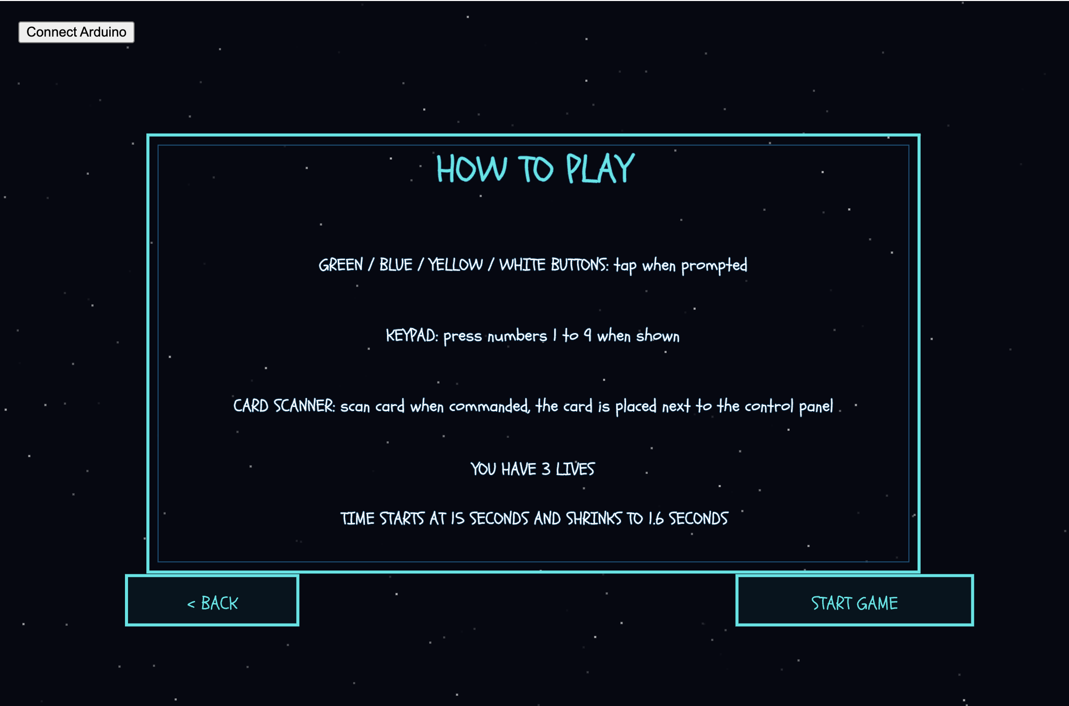
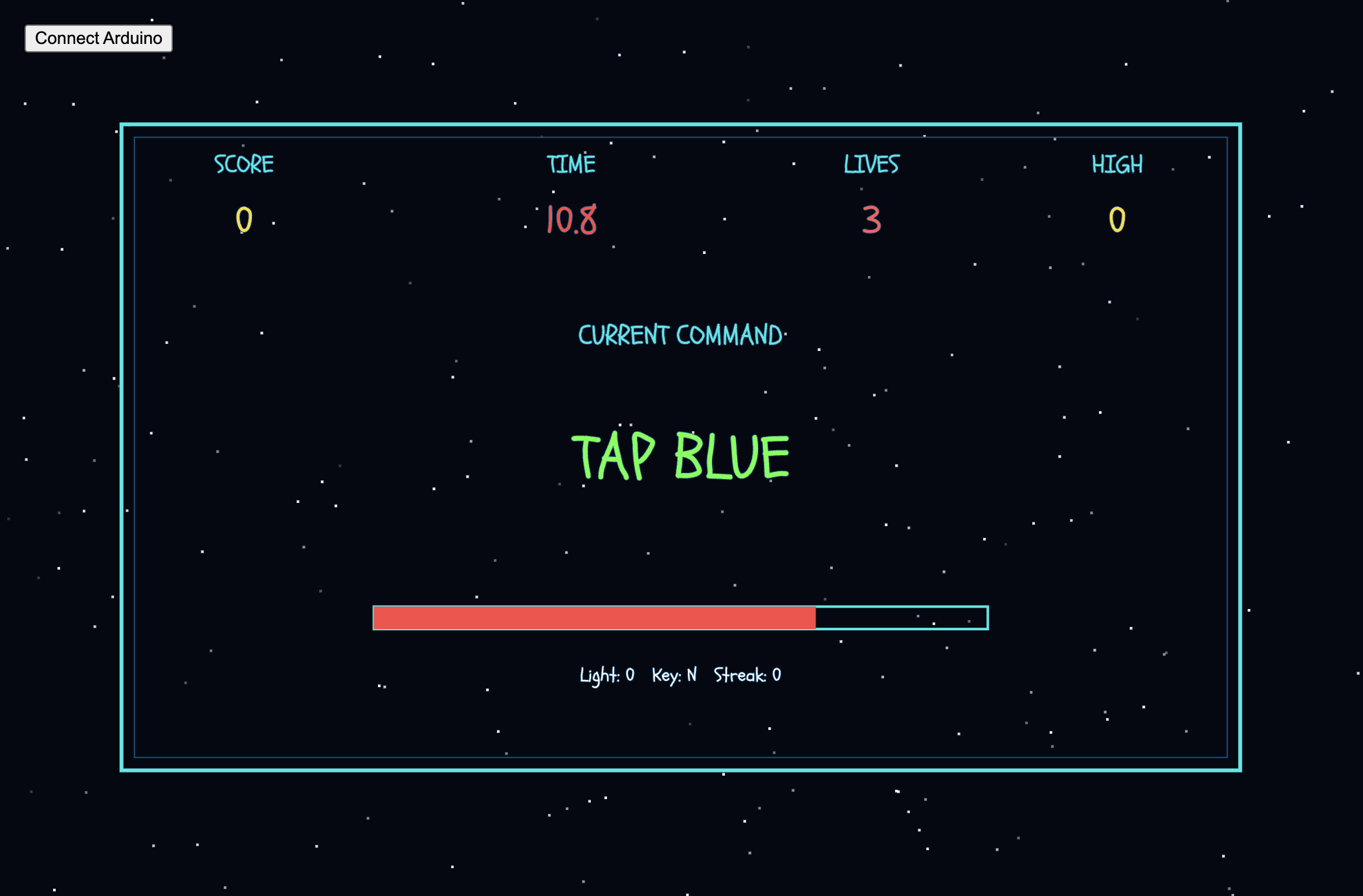
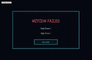
Concept:
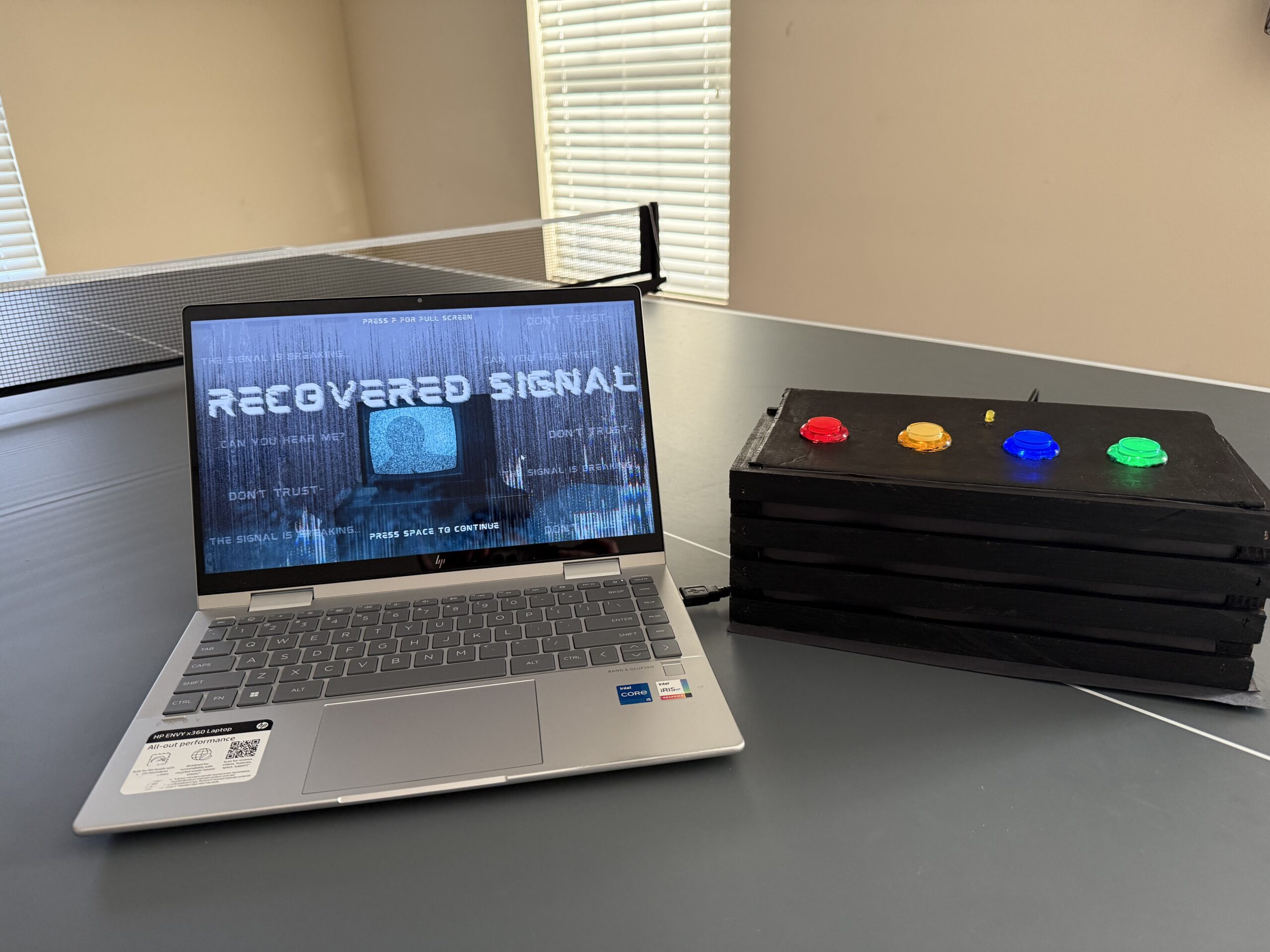
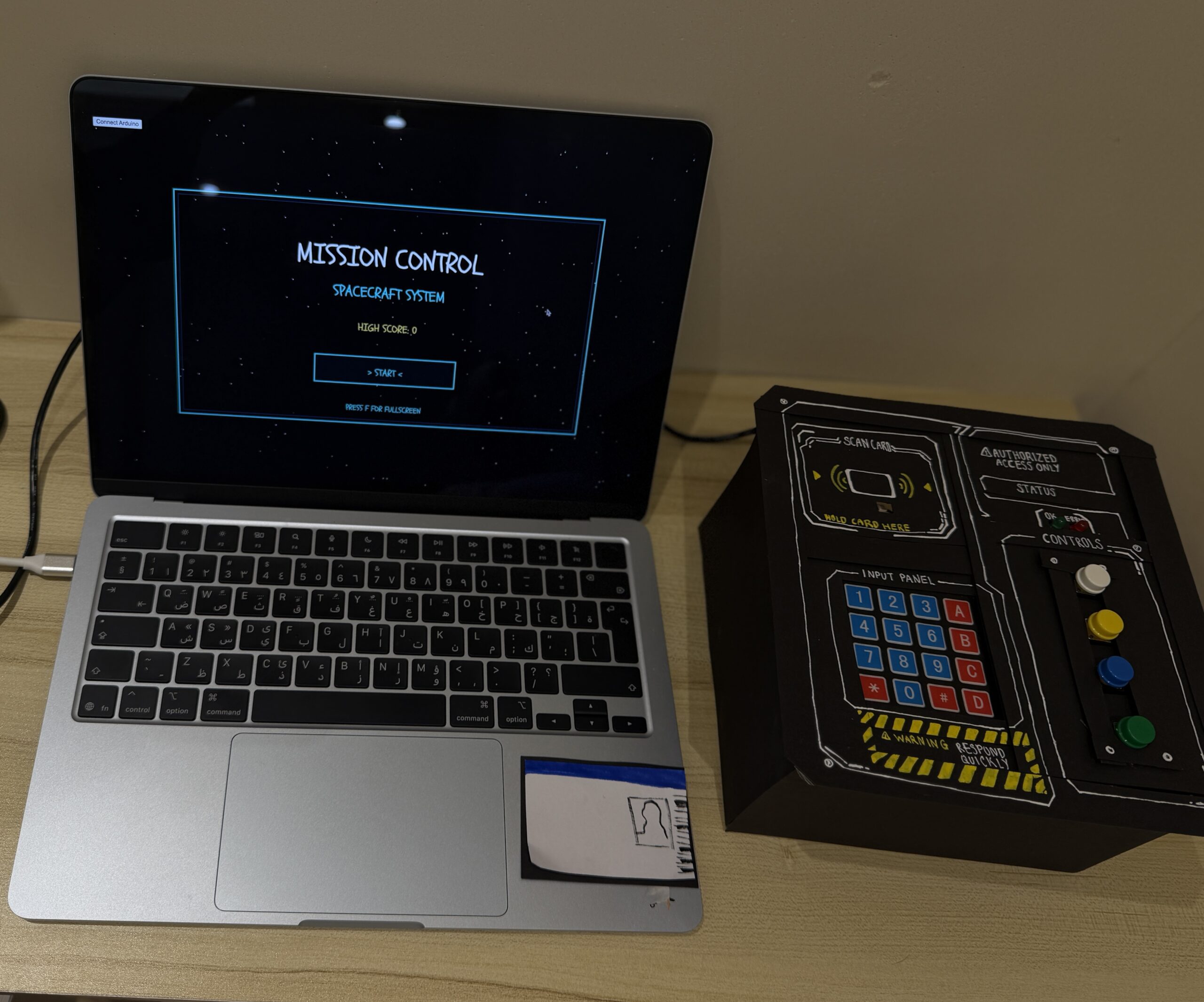
For my final project, I created an interactive simulation called Brew Your Coffee, which the title itself reflects clearly. Inspired by my love of coffee, and specifically the process of making a cup of coffee, I wanted to create an experience where the user could go through a fun and interactive coffee-brewing simulation using both a p5 sketch and Arduino physical components.
The project aims to create a realistic and engaging experience through a self-made coffee machine model that includes actual coffee-making objects and a sensor that detects the user’s physical movements. By following the provided guide and completing each step, the user gets to simulate brewing their own freshly made cup of coffee!
Visual Documentation:
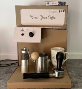
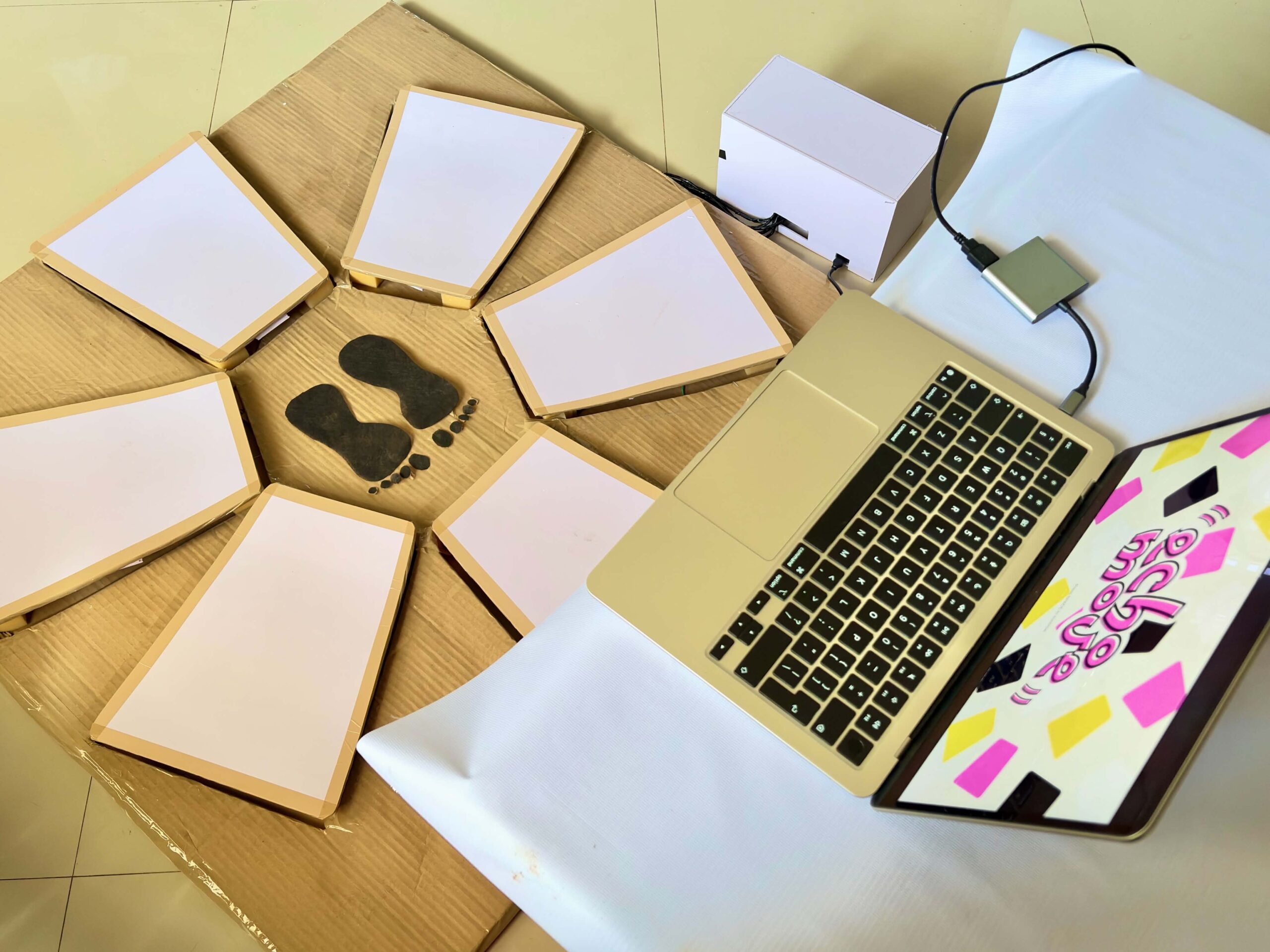
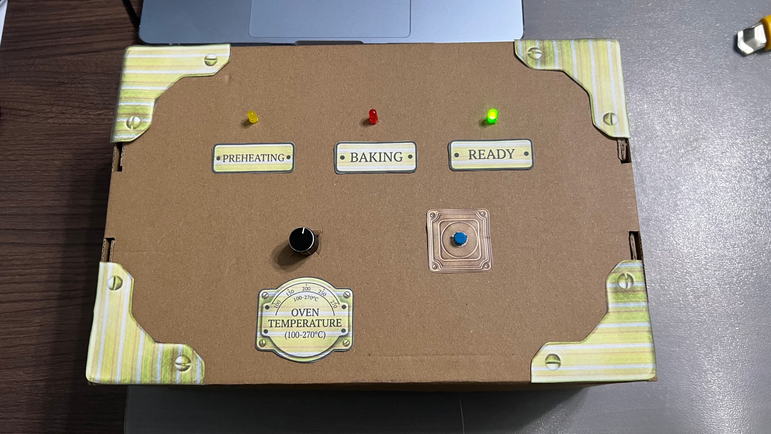
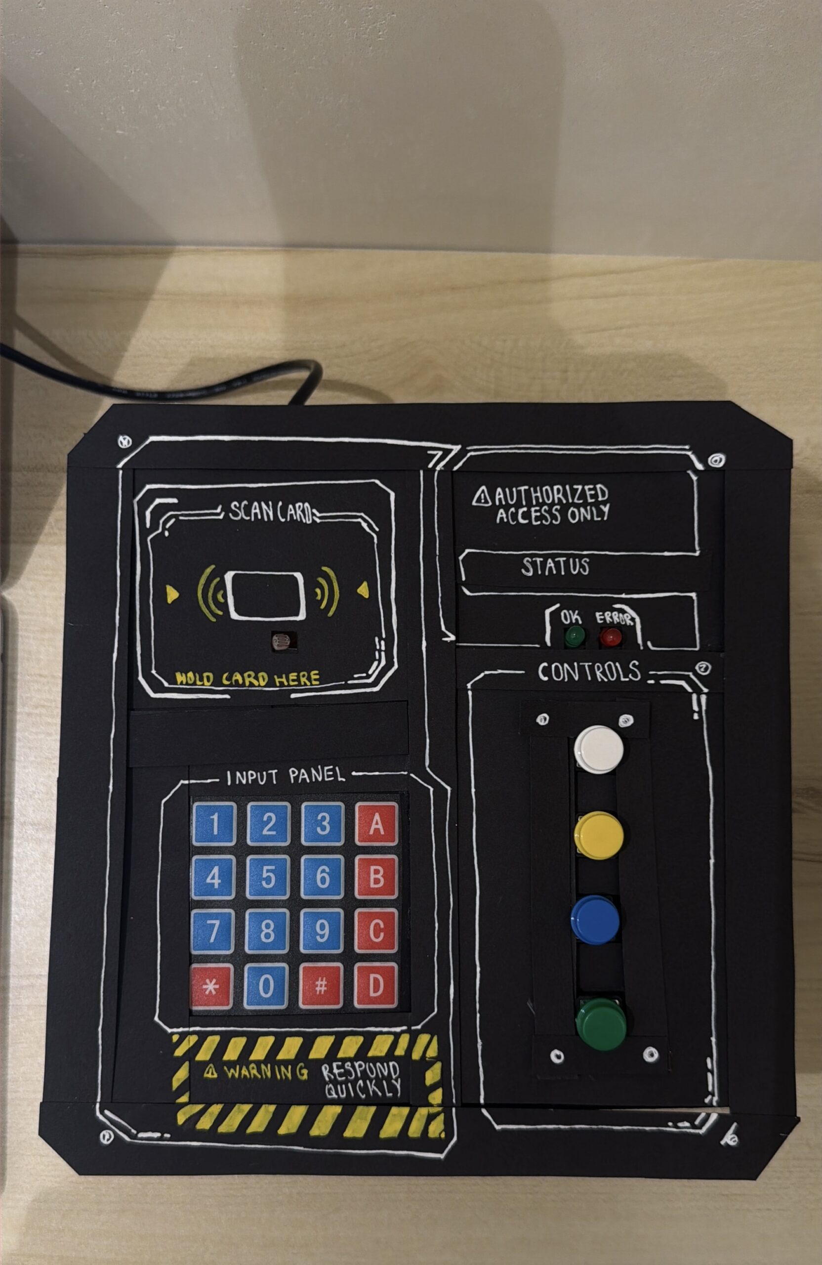
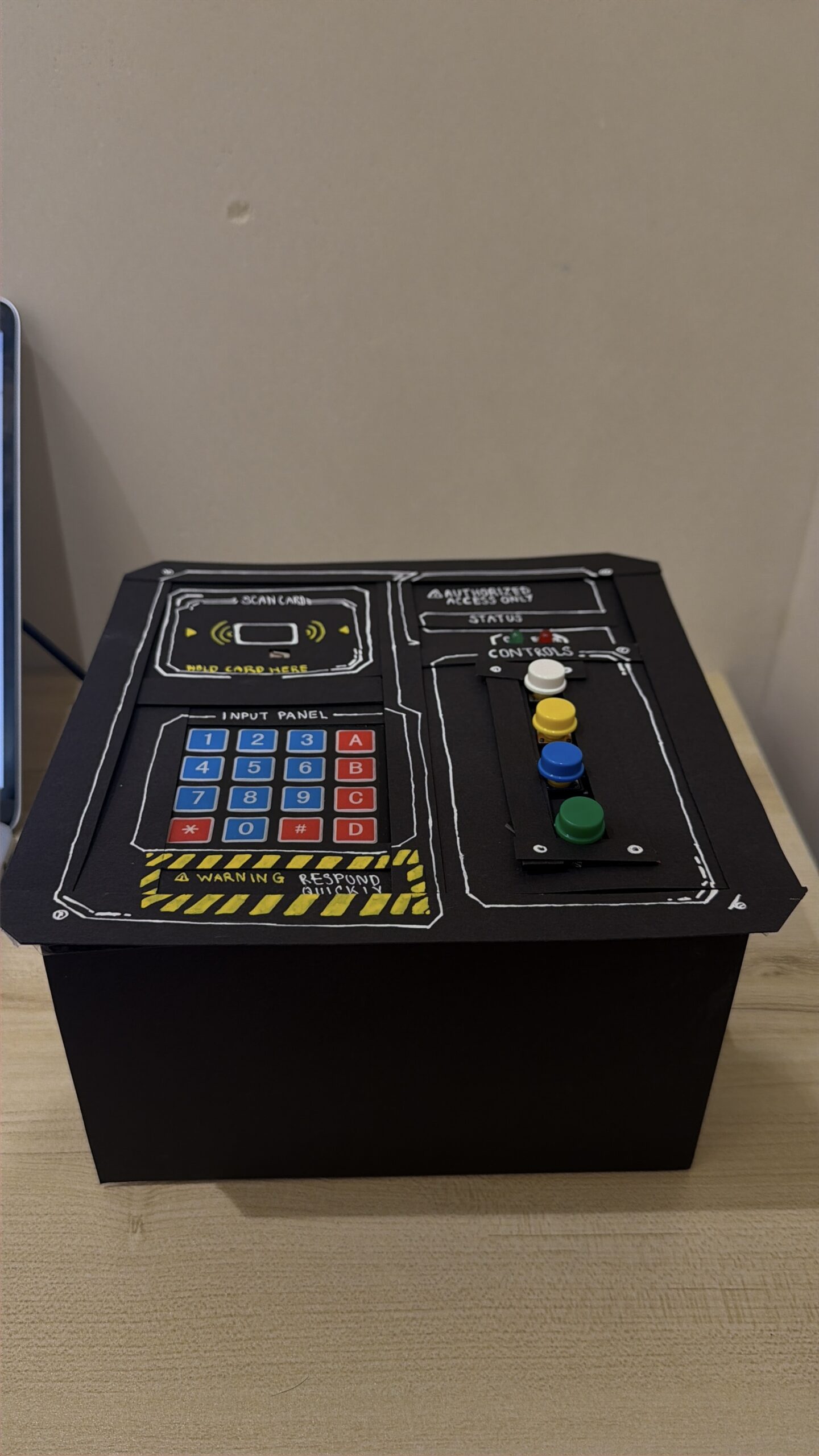
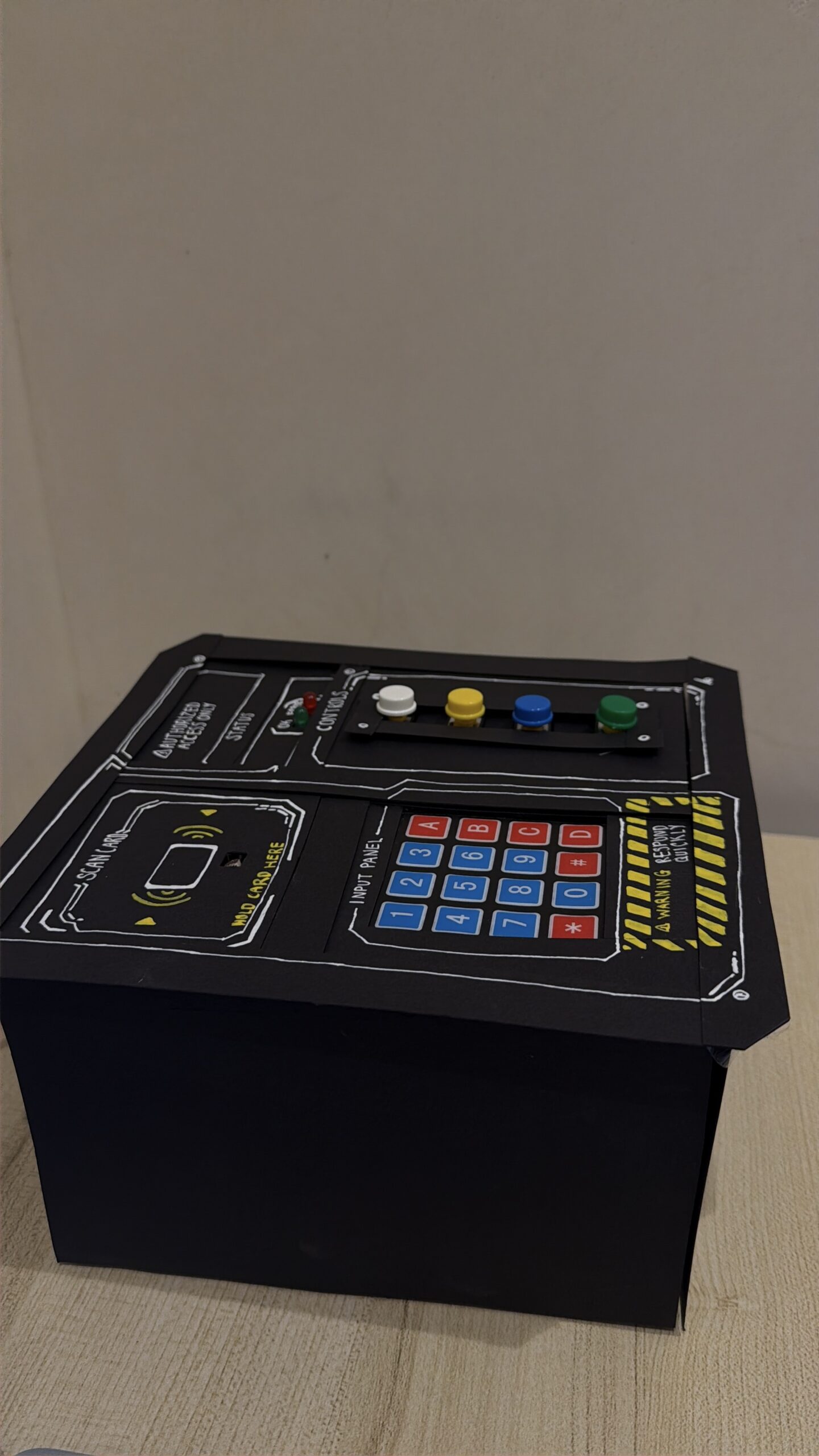
For the main model, I mainly used cardboard. I measured and cut the pieces using a cutter, then assembled and attached them together using a hot glue gun.
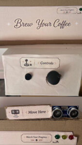
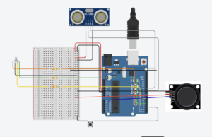
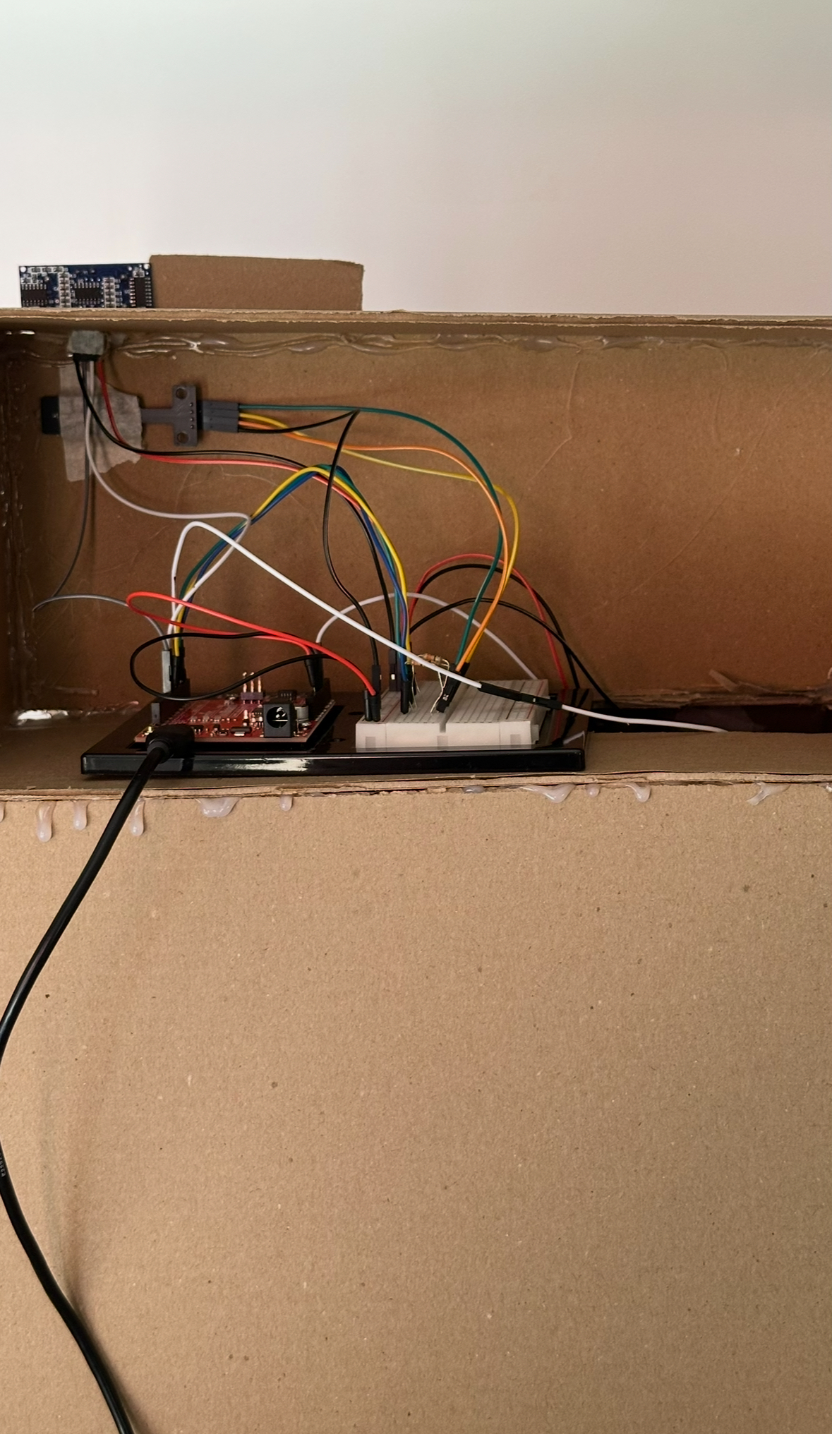
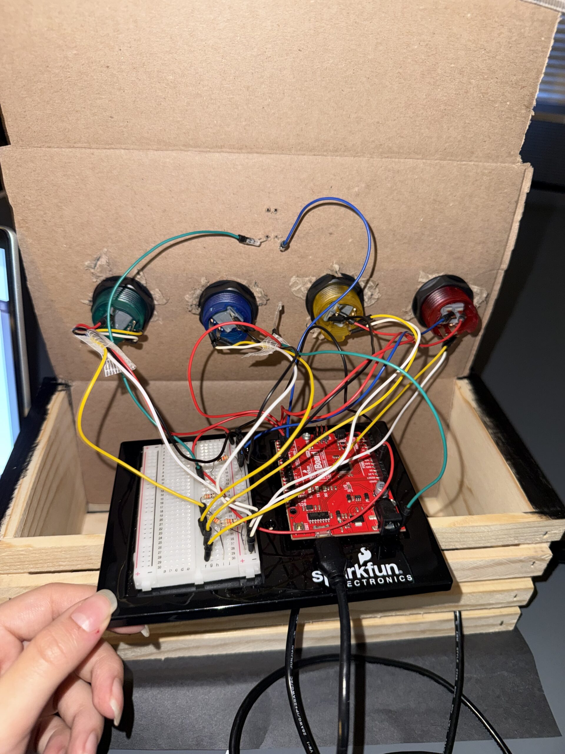
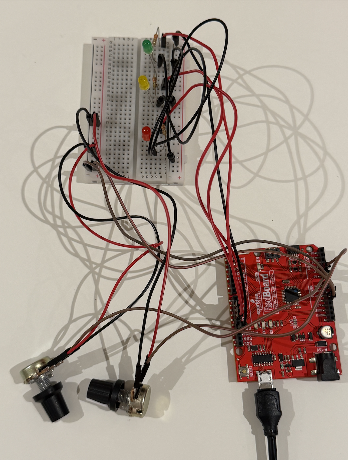
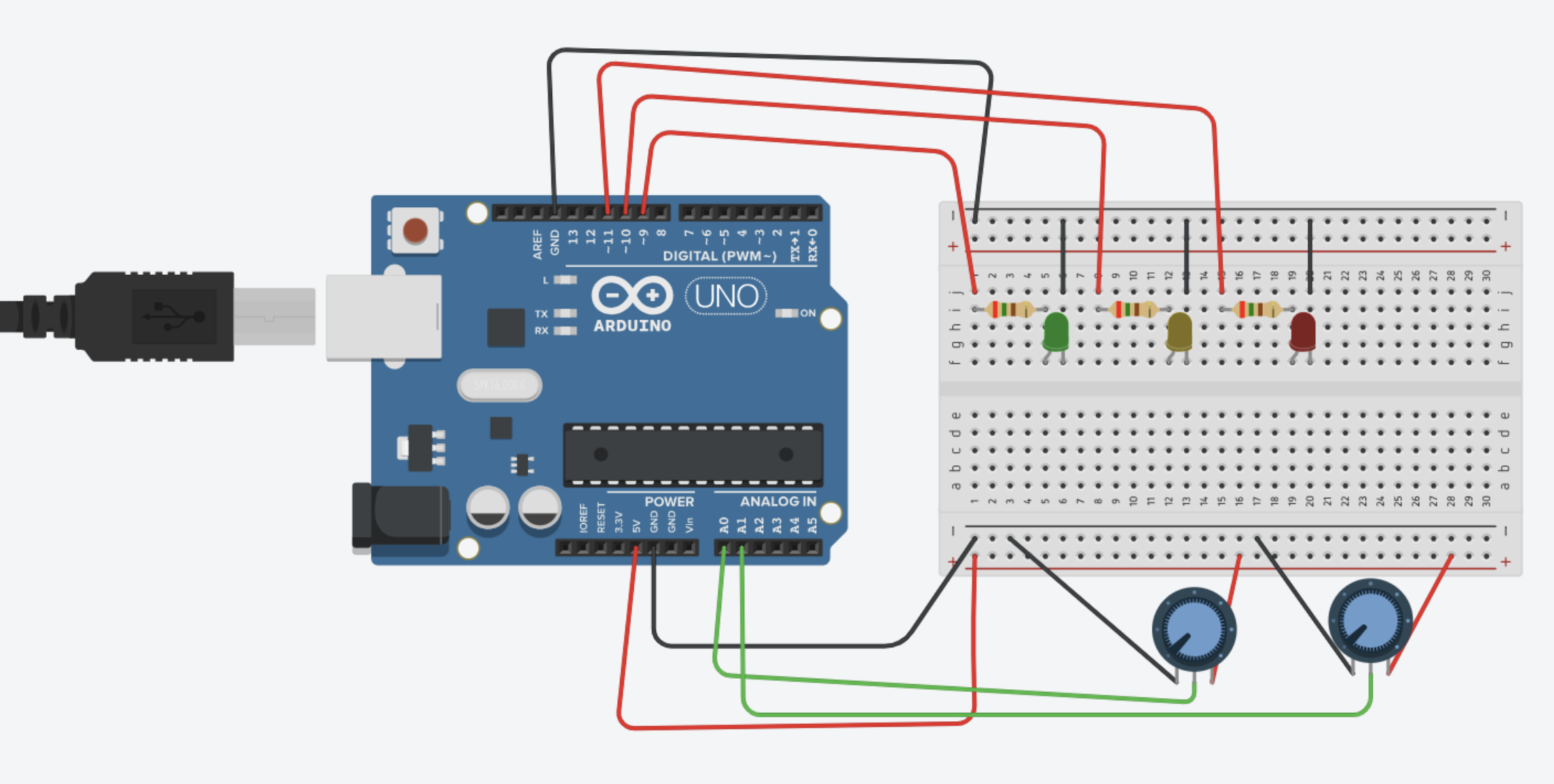
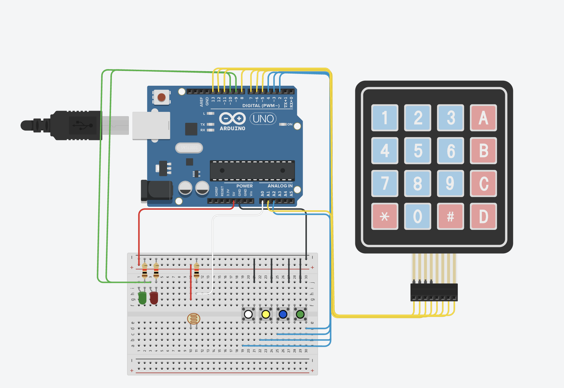
I first created openings for the visible components, including the button, joystick, LED module, and ultrasonic sensor, then started setting everything up using the Arduino, breadboard, jumper wires, and female-to-male jumper wires for the components that needed longer connections.
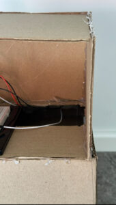
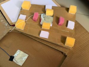
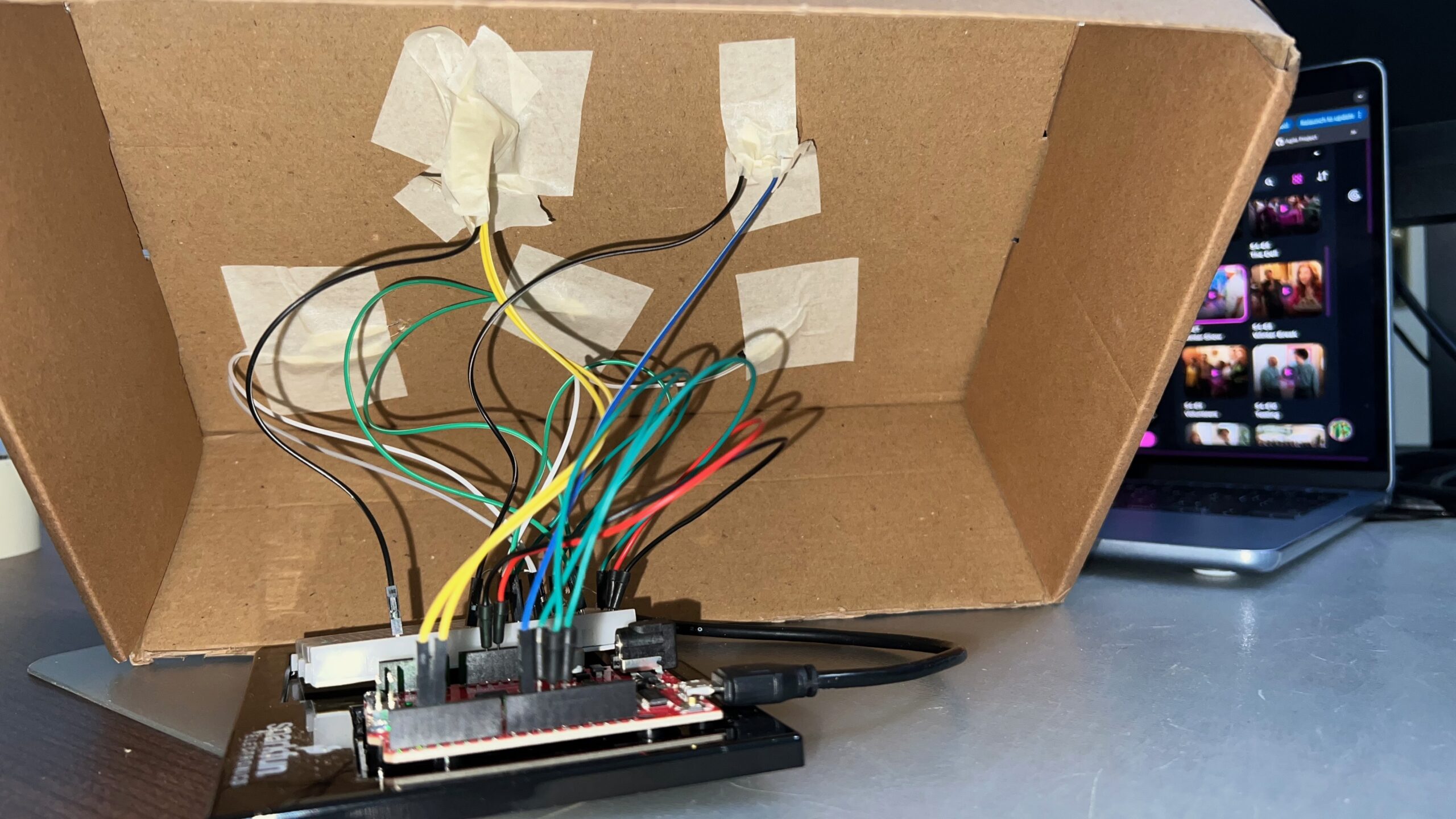
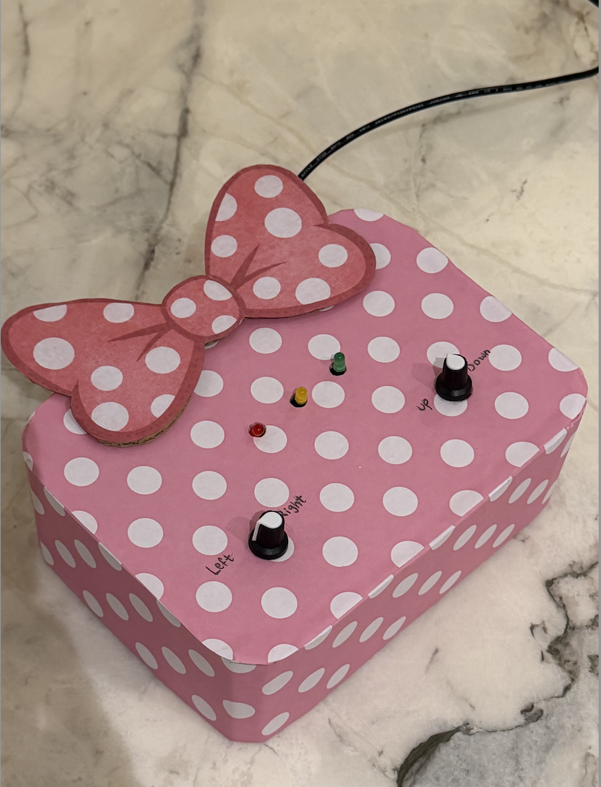
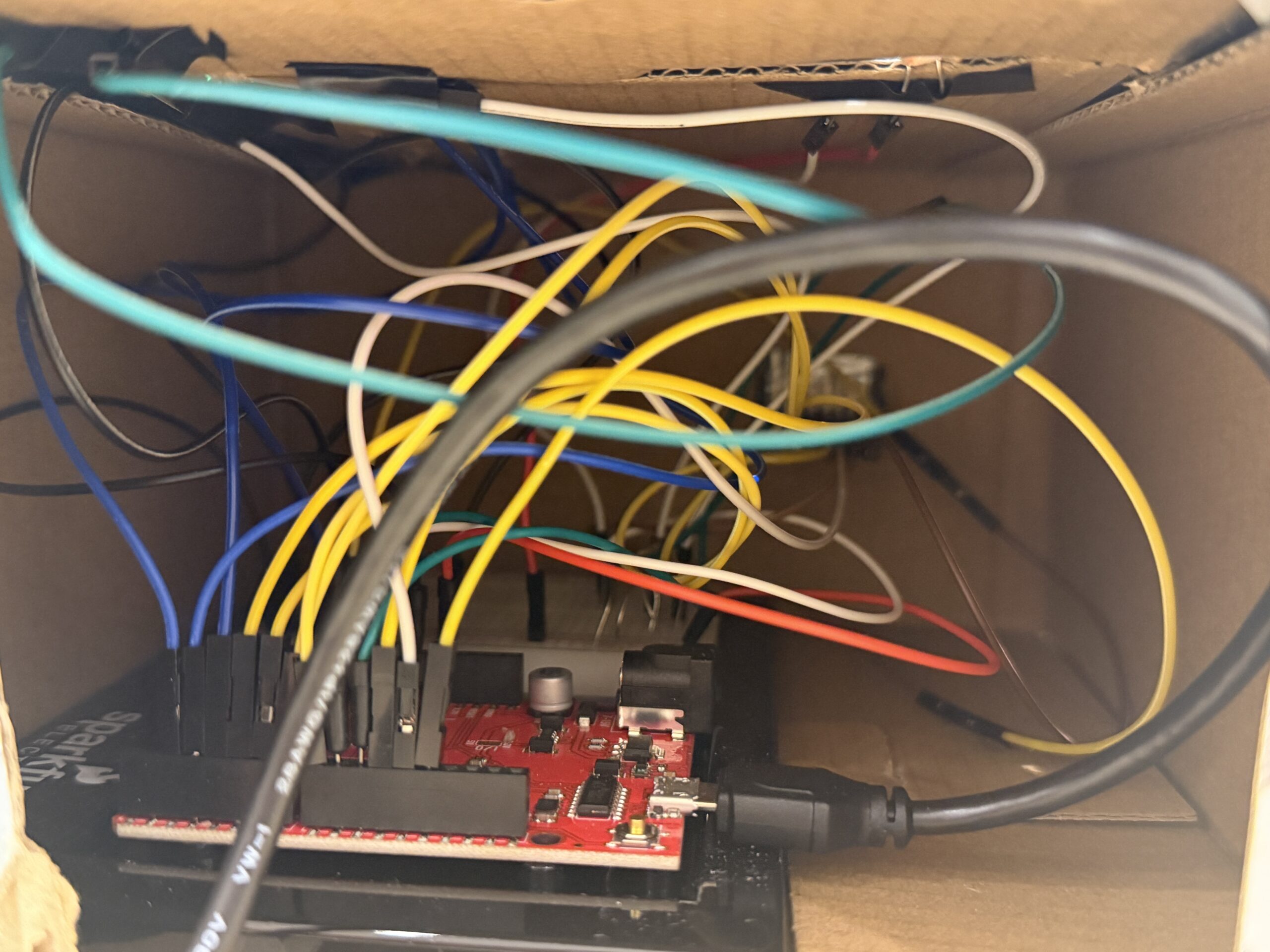
Here is the back of my model showing the wiring setup. The lower opening contains the joystick and button wires extending downward into the popped-out tilted section to make the controls more comfortable and easier for the user to interact with.

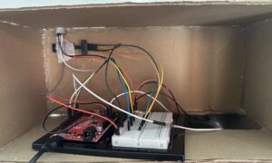
After securing the wiring and making sure the Arduino setup was functioning correctly, I assembled the structured pieces together into the coffee machine model I had envisioned. I then added the title of the simulation as the name of the machine, along with labels for the different components such as the controls, sensor, and LEDs to make the interaction clearer for the user. I also decided to include actual coffee-making objects that matched the visuals shown on the p5 sketch in order to create a more realistic and immersive experience.
Setup:
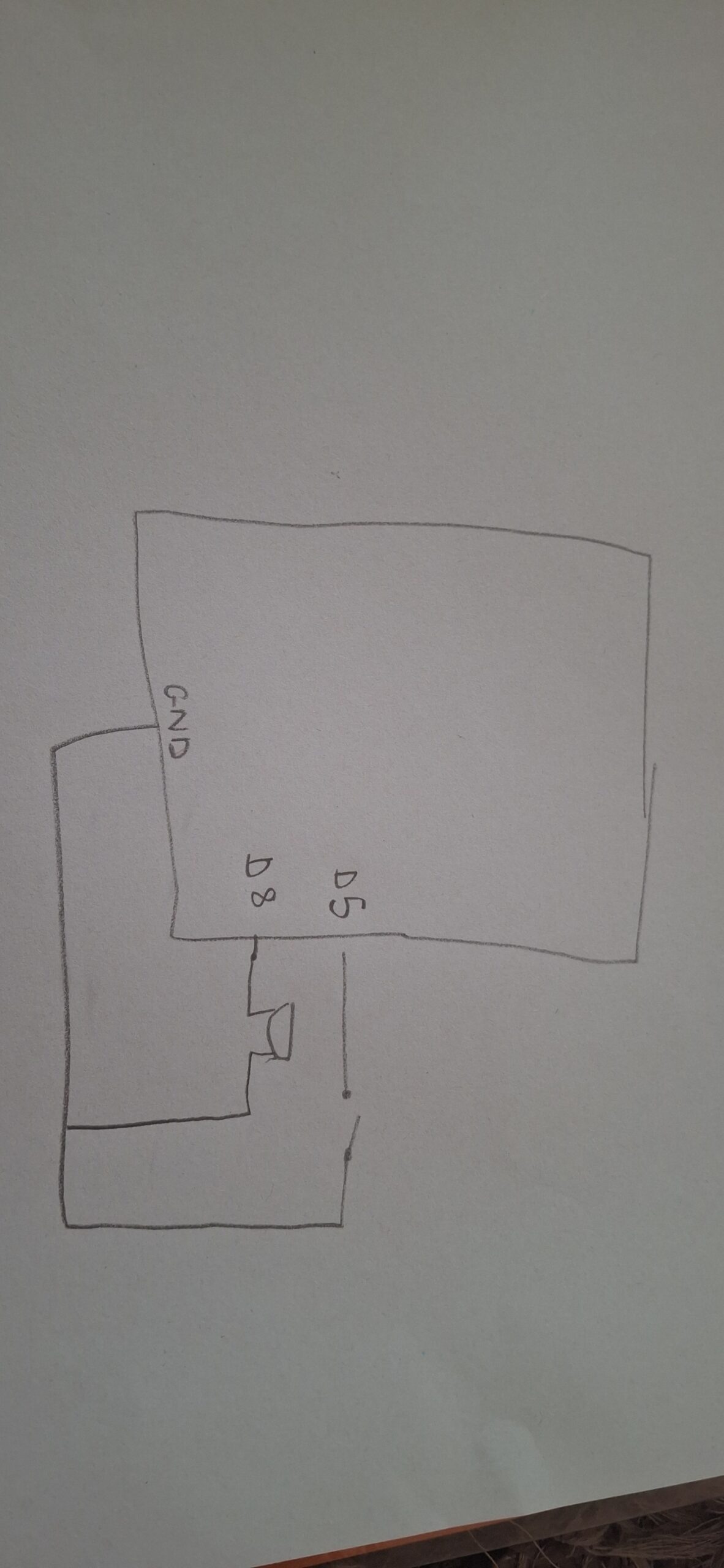
Fully aligned with the actual arduino:
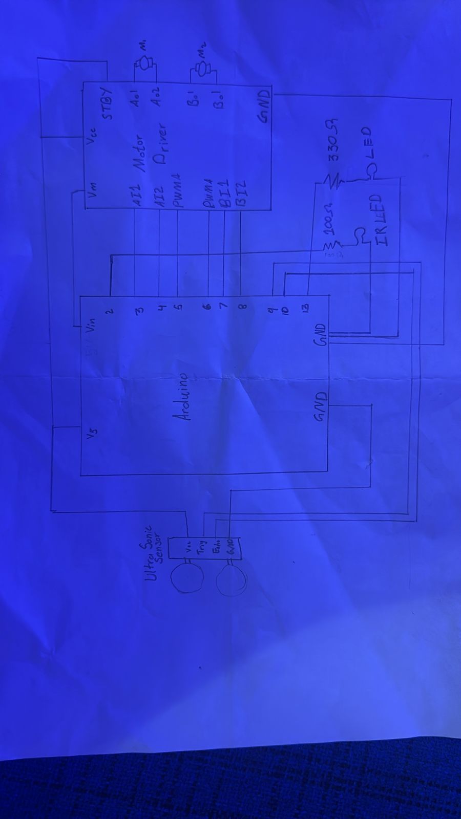
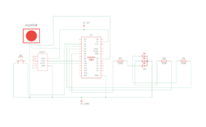
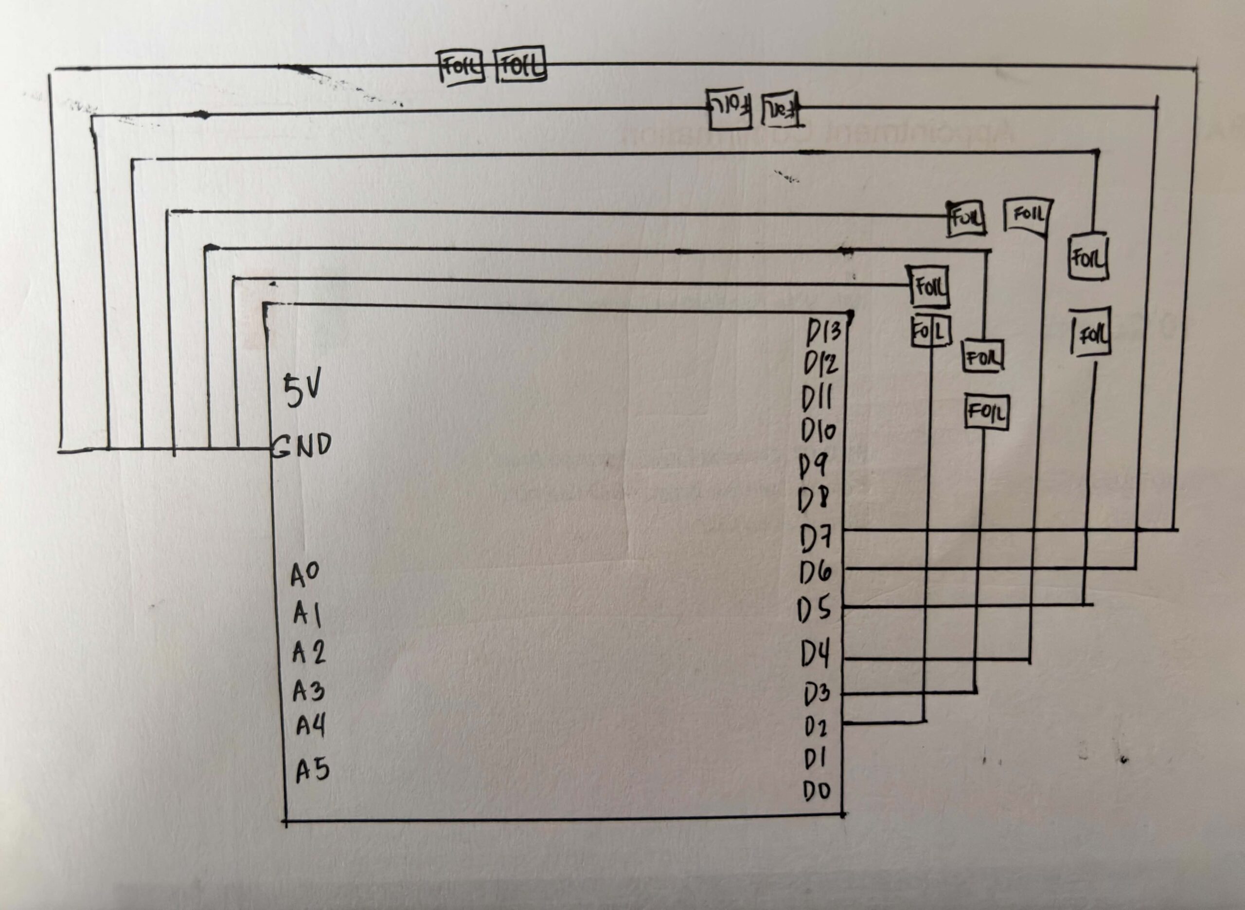
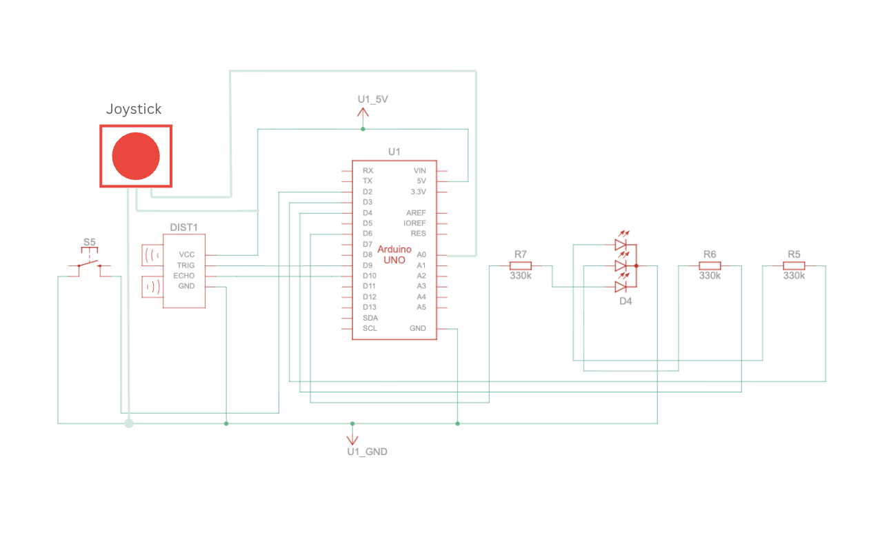
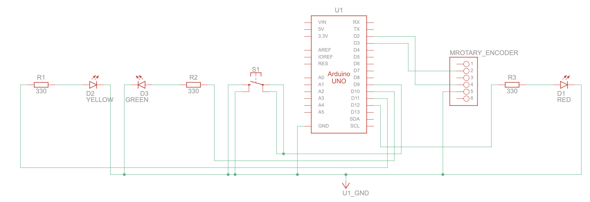
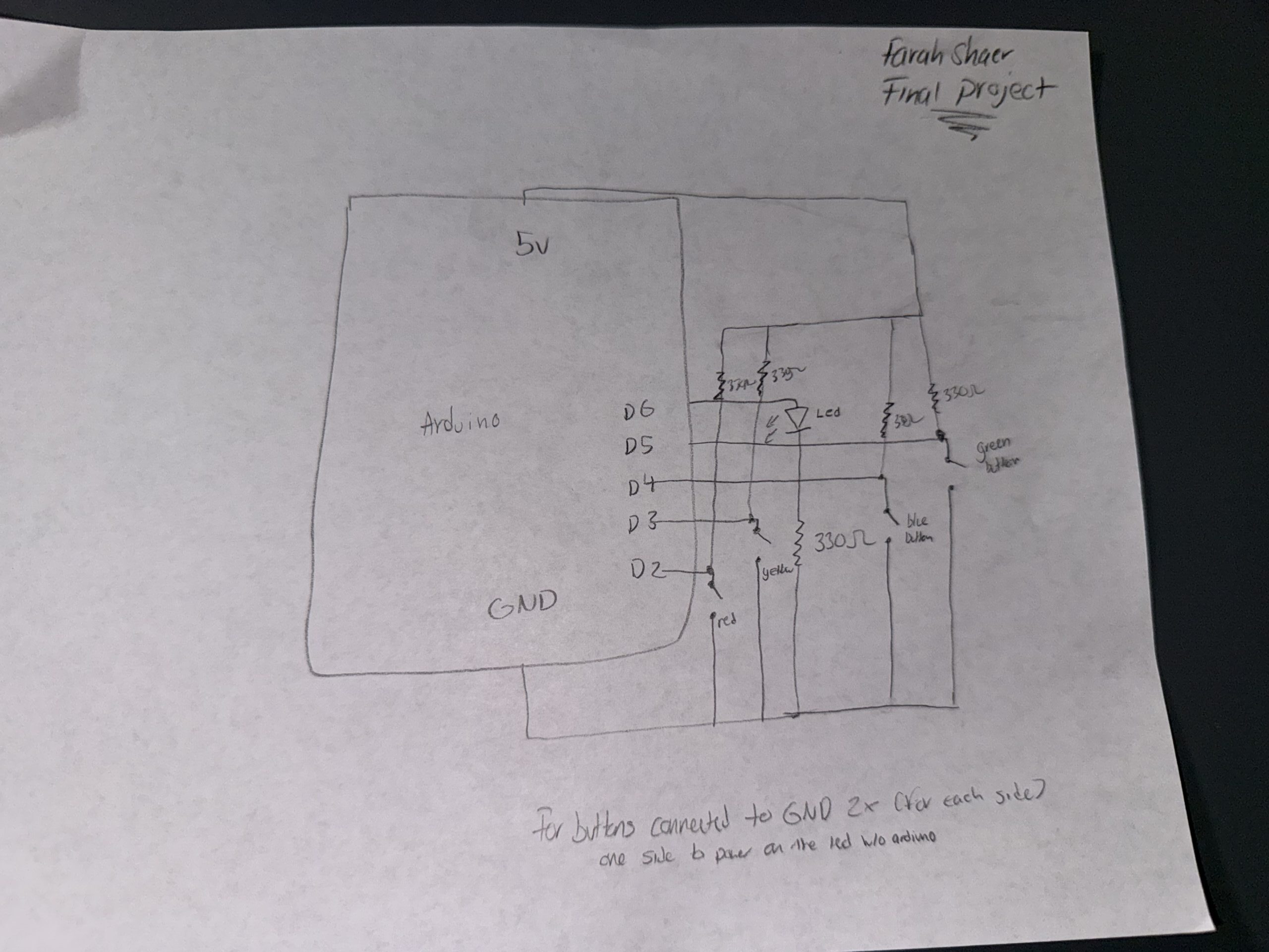
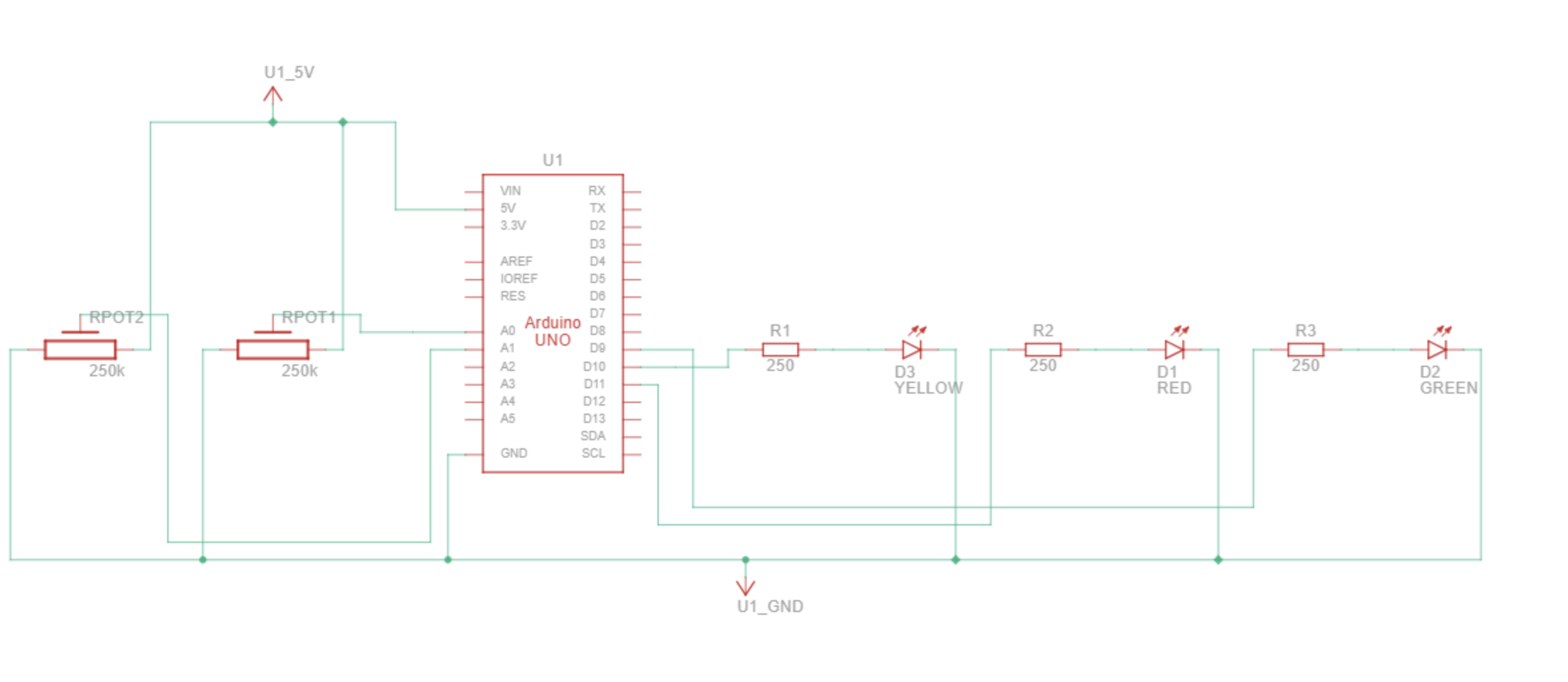
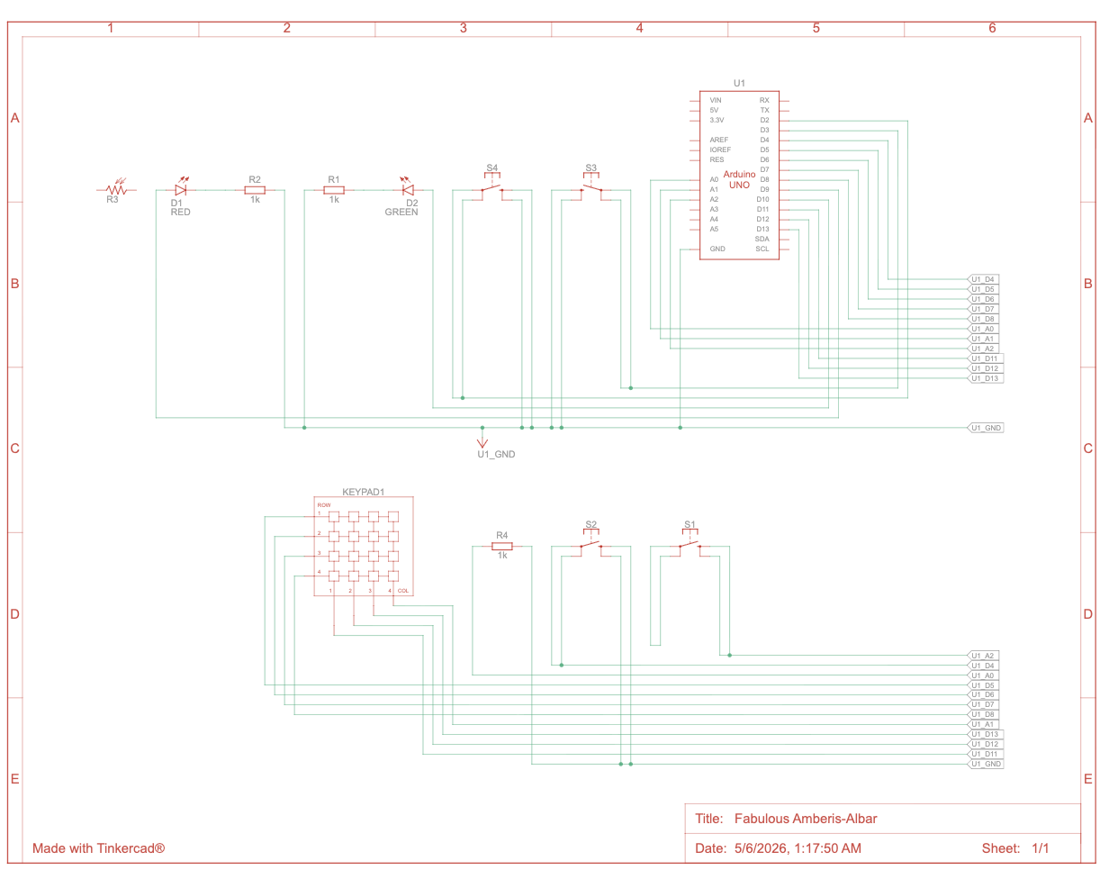
Schematic:
User Testing:
Interaction design:
The interaction design of my project was created to make the experience feel simple, clear, and realistic for the user. I wanted the interaction to imitate the actual process of making coffee while still being easy and enjoyable to understand.
The user first moves through the different screens using the physical button and joystick attached to the Arduino setup. The joystick allows them to navigate between the coffee-making steps, while the button is used to confirm selections and move forward in the experience.
Once an action begins, the interaction changes from button-based navigation to physical movement. The ultrasonic sensor detects the user’s hand movements in front of the coffee machine model, which then progresses the animations on the p5 sketch with audio. This was designed to make the user feel more involved in the process rather than only pressing buttons on a screen.
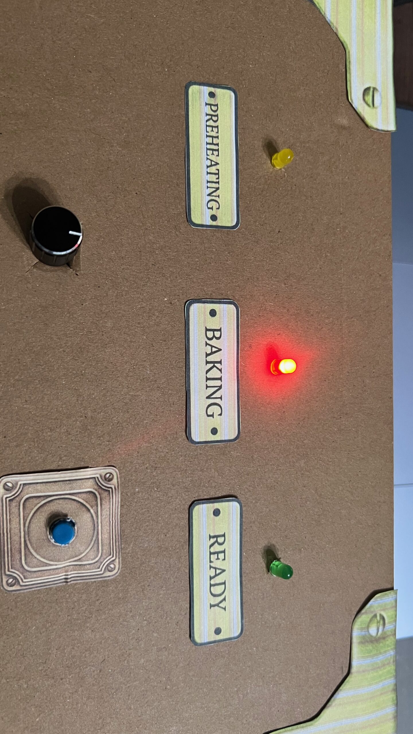
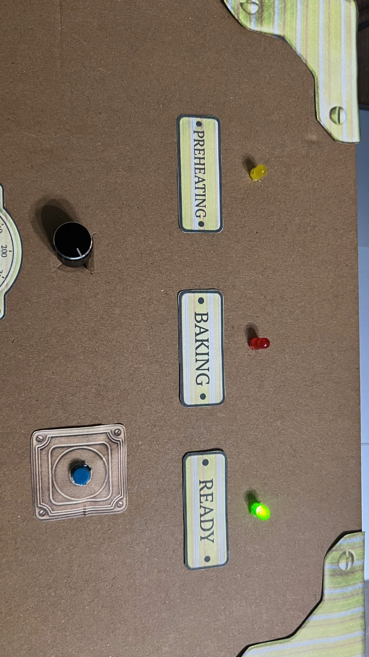
The LED lights were also part of the interaction design and acted as visual feedback for the user. Red indicates that the action is ready to begin, yellow shows that movement is currently being detected, and green indicates that the step has been completed successfully. Along with the sprite animations and sound effects, these interactions helped make the experience feel more responsive and immersive.
Arduino code:
The Arduino code handles all the physical interactions of the project, including the joystick, button, ultrasonic sensor, and RGB LED module. It detects the user’s inputs, sends simple serial signals to the p5 sketch for navigation and movement interactions, and receives signals back from p5 to control the LED feedback colors during the experience.
Link to GitHub Code
One of the key parts of the code was the joystick navigation between the coffee-making options. The joystick continuously reads analog values from the X-axis, and depending on the direction the user moves it, the Arduino sends either L for left or R for right to the p5 sketch through serial communication. I also added threshold values and timing delays so the navigation would feel smoother and avoid rapidly repeating the same signal multiple times from one movement. This made the interaction more controlled and easier for the user to navigate.
// Joystick left & right navigation
  int joystickX = analogRead(joystickXPin);

  // Send "L" or "R" when joystick passes threshold, using delay to avoid rapid repeated signals
  if (millis() - lastJoystickTime > joystickDelay) {
    if (joystickX < joystickLeftThreshold) {
      Serial.println("L");
      lastJoystickTime = millis();
    } else if (joystickX > joystickRightThreshold) {
      Serial.println("R");
      lastJoystickTime = millis();
    }
Another important part of the code was the ultrasonic sensor interaction. The sensor measures the distance between the user’s hand and the coffee machine setup. To make the interaction feel realistic, I did not only check the distance itself, but also checked whether the distance was changing enough to count as actual movement. This avoids possible triggering and helped make the animations progress only when the user was actively moving their hand in front of the sensor. I also used threshold ranges and delays to make the motion detection more stable and responsive.
// Movement detection using ultrasonic sensor
  int distance = detectDistance();
  int difference = abs(distance - lastDistance);

  // Send "M" when an object is within range and its distance changes enough to indicate movement
  if (millis() - lastMotionTime > motionDelay) {
    if (distance > minMotionDistance && distance < maxMotionDistance && difference > motionChangeThreshold) {
      Serial.println("M");
      lastMotionTime = millis();
    }
P5.js code:
The p5 code controls the visual and interactive side of the project, including the screens, sprite sheet animations, audio, and overall experience flow. It receives signals from Arduino to activate the interface and progress the actions, while also sending signals back to Arduino to align the LED feedback with the current interaction state.
One of the major parts of the code was creating and controlling the sprite sheet animations for each coffee-making action. I created a class to organize the actions and make each animation easier to manage. The animations work by increasing a progress value whenever movement is detected from the ultrasonic sensor. That progress is then mapped to different frames of the sprite sheet using the map() function. I also used constrain() to make sure the frame number never goes outside the sprite sheet range. Once the action reaches its maximum progress, the animation locks onto the final frame and marks the action as completed.
// Map interaction progress to sprite sheet frames
   this.frame = floor(map(this.progress, 0, maxProgress, 0, this.totalFrames));
   this.frame = constrain(this.frame, 0, this.totalFrames - 1);

   // Lock animation on the final frame once complete
   if (this.progress >= maxProgress) {
     this.frame = this.totalFrames - 1;
     this.done = true;
   }
 }
Another important part of the code was combining audio and LED feedback with the movement interactions. Whenever the user performs movement detected by the ultrasonic sensor, the correct sound effect begins playing depending on the current action. At the same time, the p5 sketch sends signals back to Arduino to control the LED colors. Once the action is completed, the audio stops and the LED changes to green to visually indicate completion to the user.
// Progresses the current action when movement is detected
function handleMovement() {
  let action = getCurrentAction();

  if (action.done) return;

  // Different actions trigger different audio feedback
  if (currentAction === "grinder") {
    grinderAudio.loop();
  }

  if (currentAction === "steamer" && !steamerAudio.isPlaying()) {
    steamerAudio.loop();
  }

  if (currentAction === "coffee" && !coffeeAudio.isPlaying()) {
    coffeeAudio.play();
  }

  action.update();

  // Once the step is completed, stop audio and switch LED to green
  if (action.done) {
    stopAudios();
    sendLed("G");
  }
}
Note: For the audio if statements, the grinder action has slightly different feedback behavior compared to the other two actions. The steamer and coffee audio only begin once the ultrasonic sensor detects movement, while the grinder audio starts when the action screen appears. I made this decision based on the grinder audio file I used, since its first few seconds are mostly silent before the grinding sound begins, which ended up aligning naturally with the user’s interaction timing.
Communication between Arduino and p5.js:
The communication between Arduino and p5.js in my project works through serial communication. The Arduino is responsible for handling all the physical interactions, such as the joystick, button, ultrasonic sensor, and LED lights, while the p5 sketch controls the visuals, animations, states, and audio on the screen.
The Arduino continuously sends simple letter signals to p5 depending on the user’s interaction. For example, when the button is pressed, Arduino sends a signal to move between screens or confirm a step. The joystick sends left and right signals to navigate between the coffee-making options, while the ultrasonic sensor sends movement signals to progress the animations during the actions.
At the same time, p5 also sends signals back to Arduino to control the LED lights. Different letters are sent depending on the state of the interaction, such as red when an action starts, yellow while the user is actively moving, and green once the action is completed.
This communication allowed both the physical Arduino setup and the digital p5 sketch to work together as one interactive system.
Aspects of the project I’m proud of:
One of the aspects I am most proud of is being able to successfully combine the visuals, interaction, and physical setup into one engaging experience. I am especially proud of finalizing the images and coding the interaction between the p5 sketch and Arduino components in a way that felt smooth, interactive, and enjoyable for the user.
I am also particularly proud of using sprite sheets and audio together to visualize movement and actions throughout the coffee-making process. Since this was completely new to me, it required a lot of experimenting, troubleshooting, and problem-solving, but I was very happy to eventually make the animations and interactions work together in a realistic and immersive way.
In addition, I am proud of my physical coffee machine model and how it turned out visually. At first, building the structure felt very challenging and almost impossible, especially because I wanted it to resemble a real coffee machine. However, through patience, planning, and problem-solving, I was able to successfully complete the model and add visual details and labels that improved both the aesthetic and the user experience.
Challenges faced and how I tried to overcome them:
Honestly, working on this project was a rollercoaster ride. Some parts went smoothly, while others were much more challenging than I expected. Most of the challenges I faced were related to the visuals and animations of the p5 sketch, especially because I created all of the images and sprite sheets from scratch using AI while still trying to achieve a very specific vision and aesthetic.
At first, the visuals were not working well and did not look as appealing or consistent as I wanted, especially the sprite sheet animations. To overcome this, I became extremely specific with the prompts and references I provided. I used exact images of the real coffee-making items I had and carefully described the animation style and movement I was aiming for. Even after that, creating the sprite sheets required a lot of patience, since many results came out incorrect or inconsistent. Eventually, after multiple attempts and feedback from the professor, I was able to achieve a result that matched my vision much better.
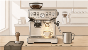
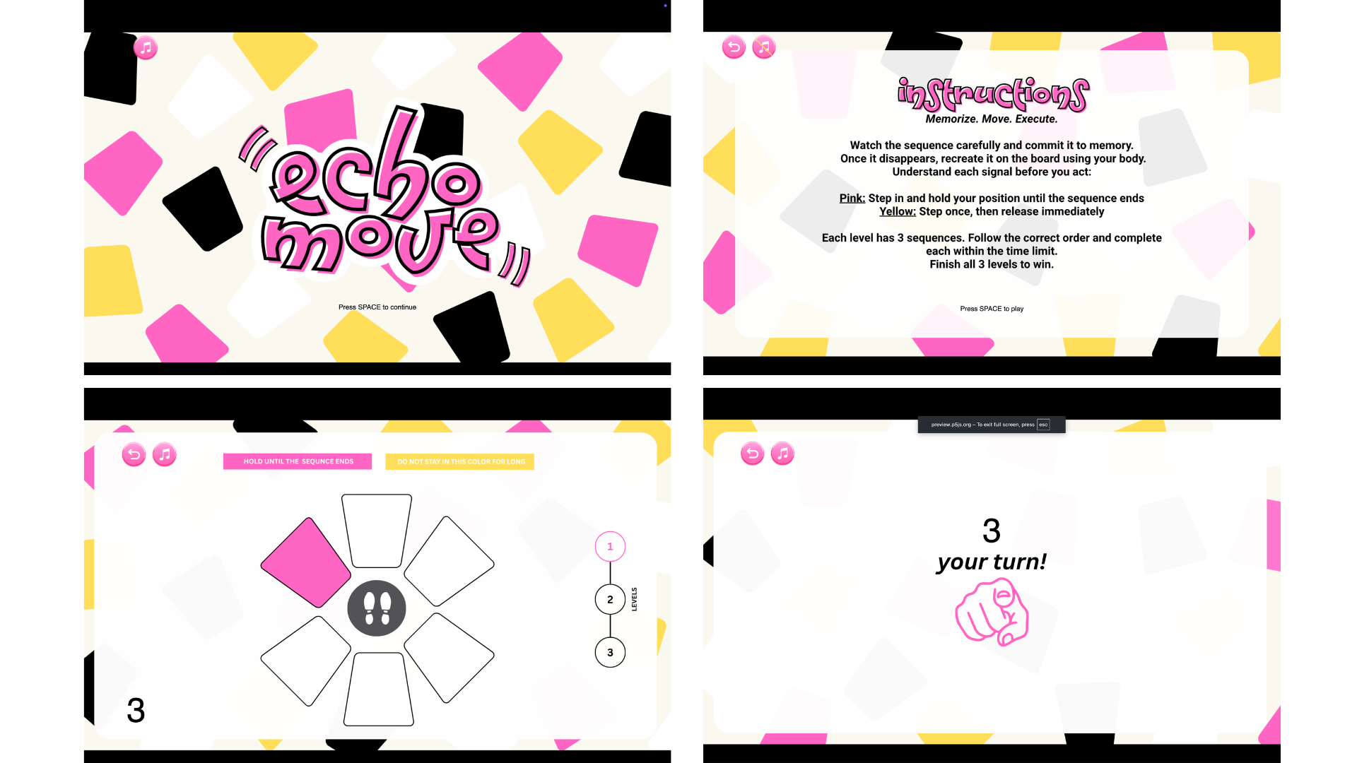
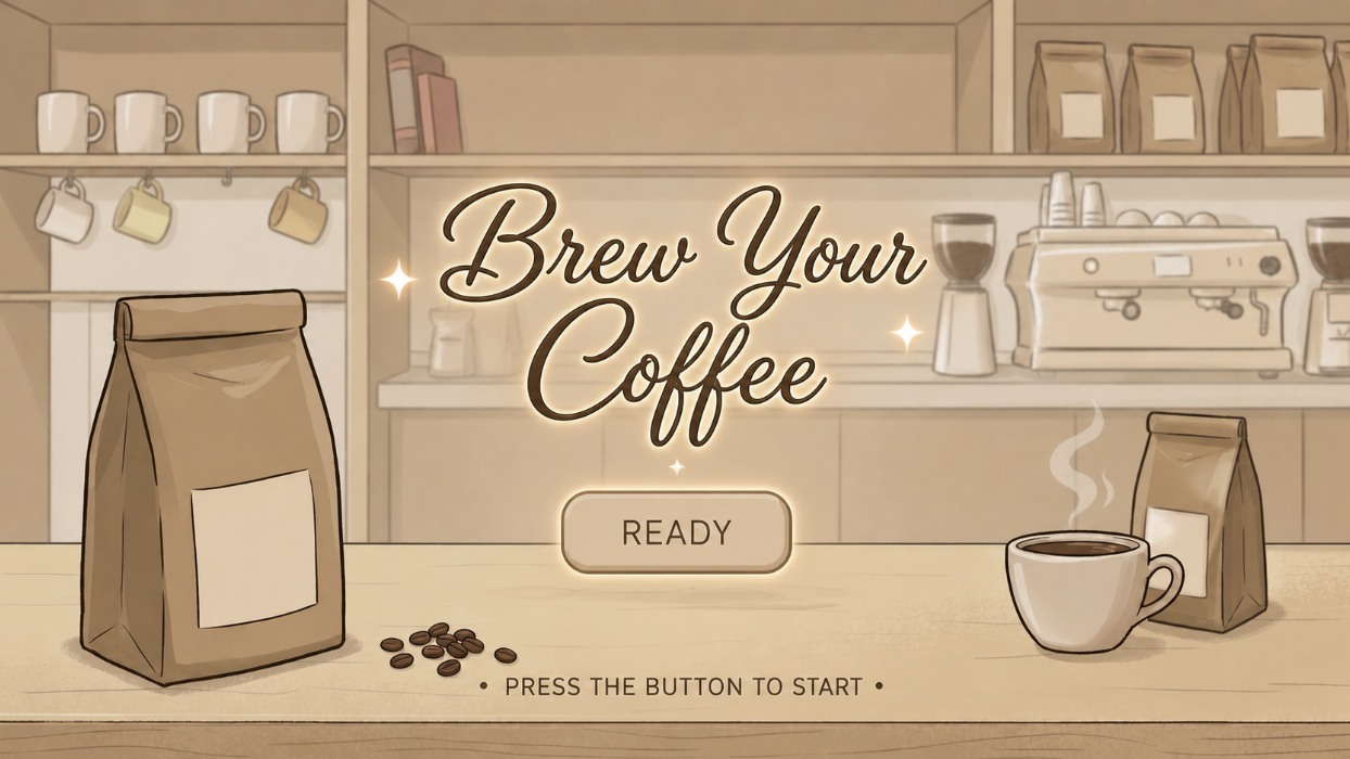
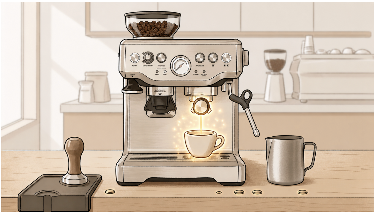
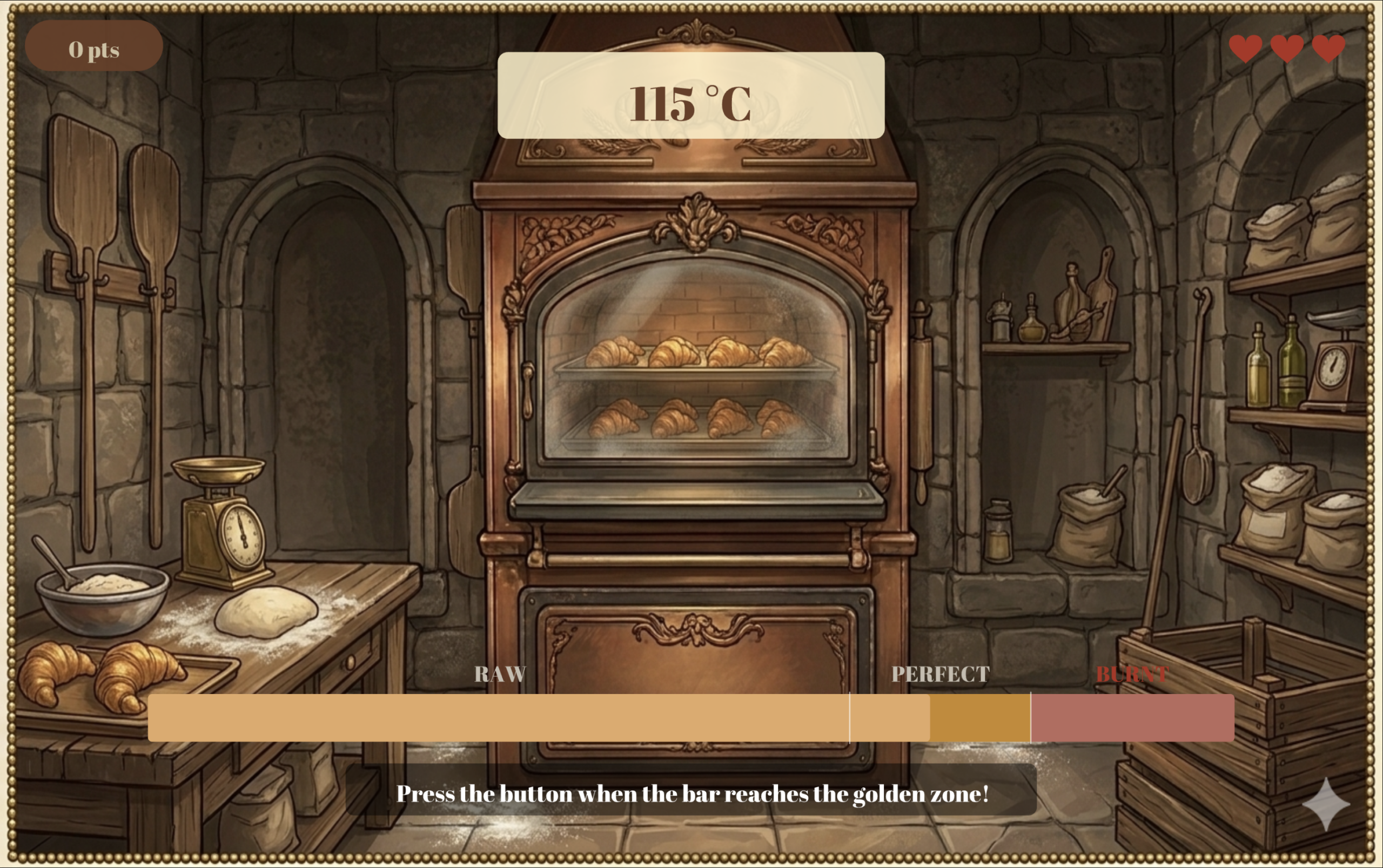
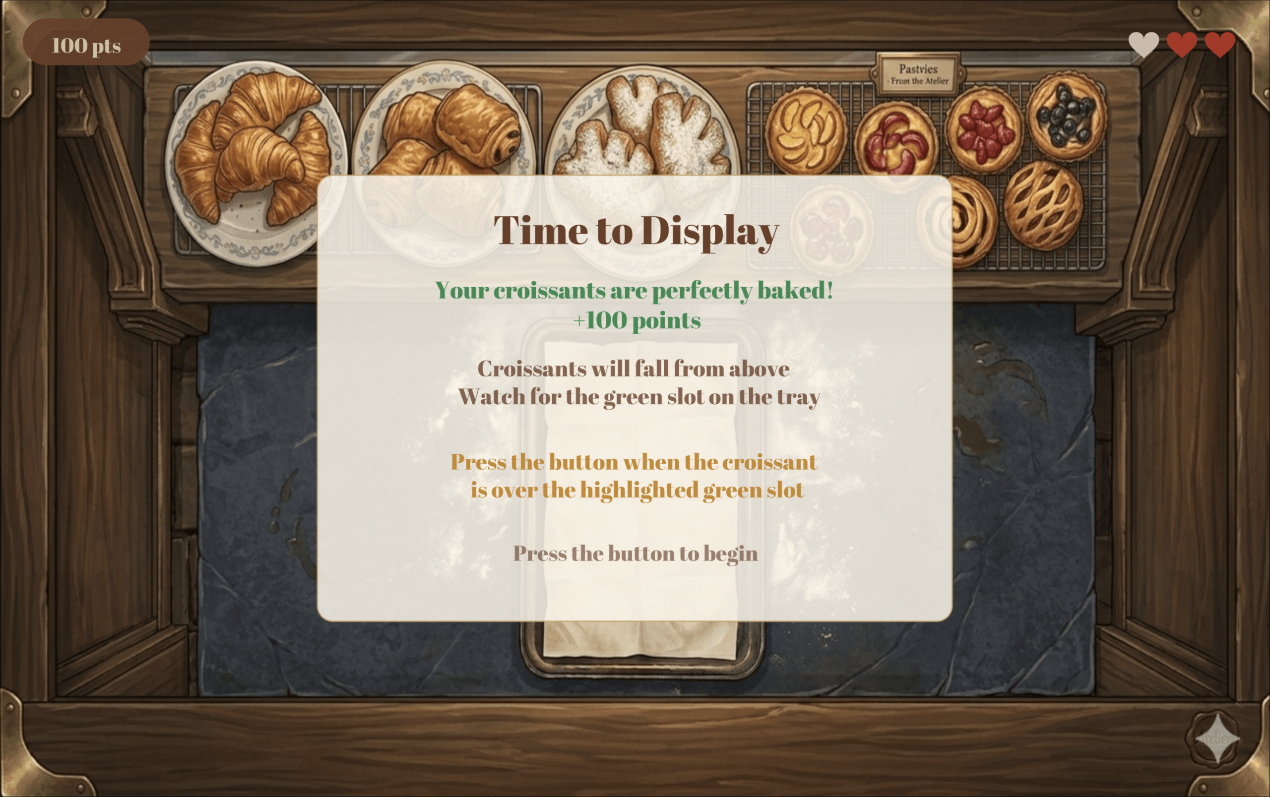
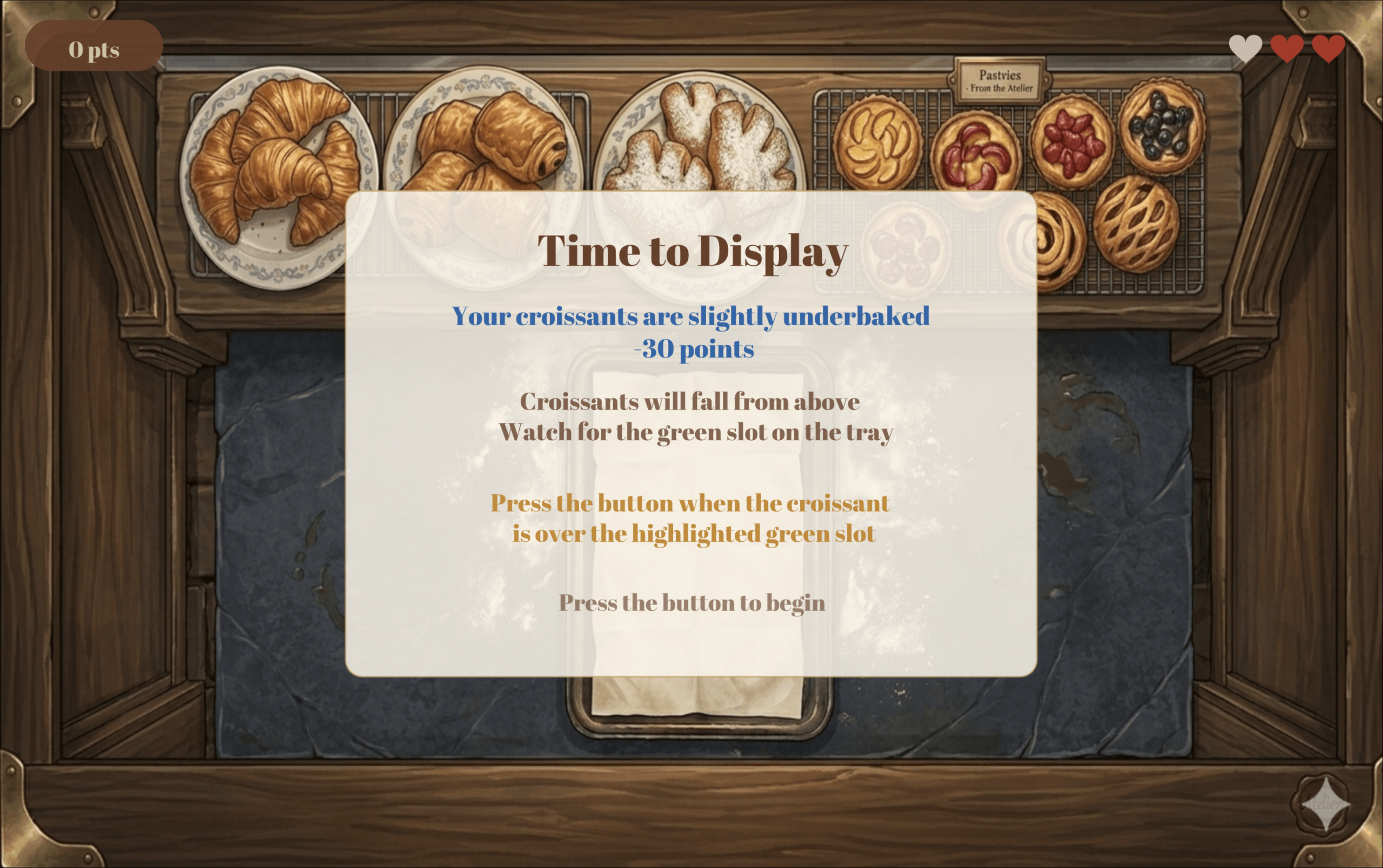
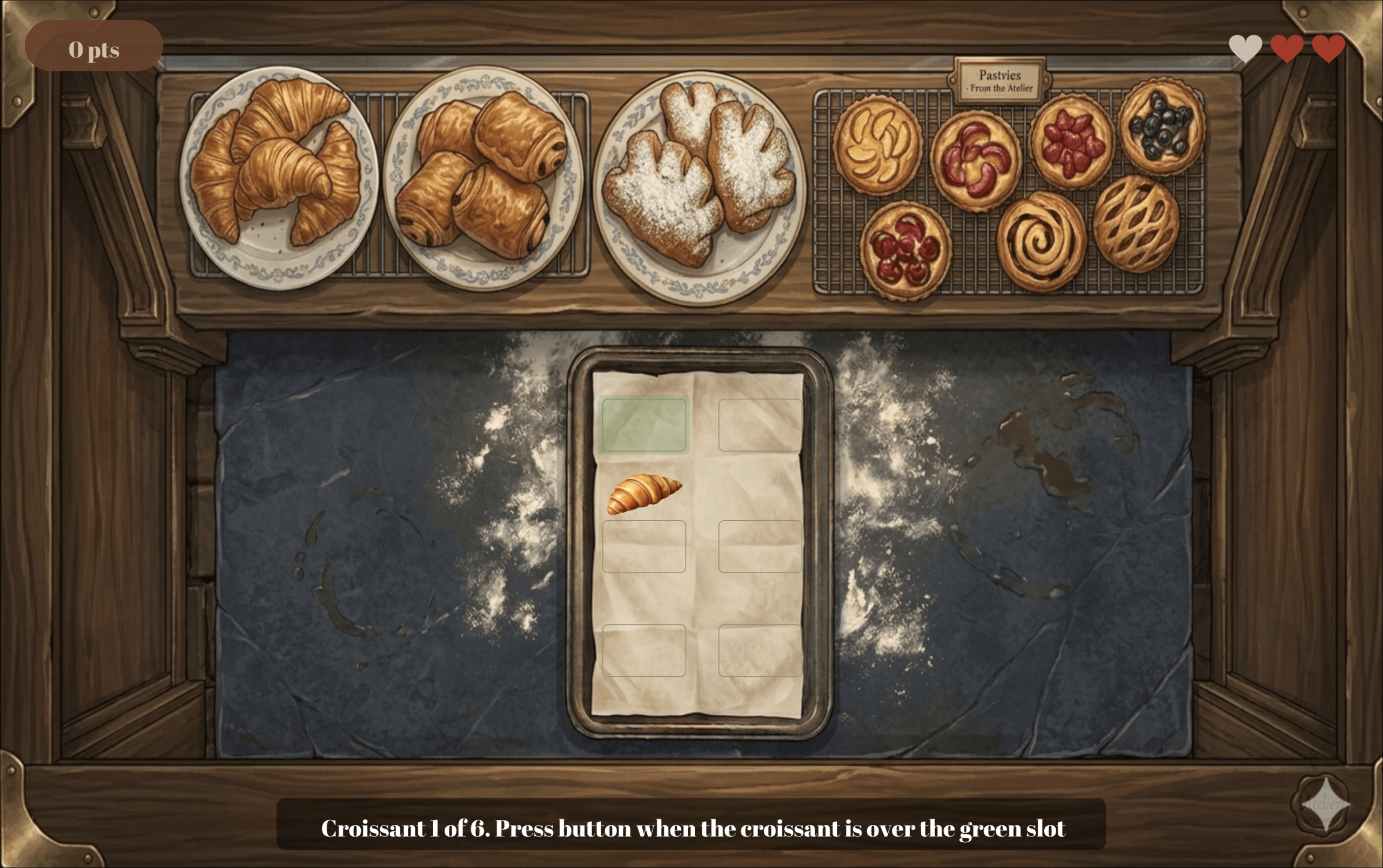
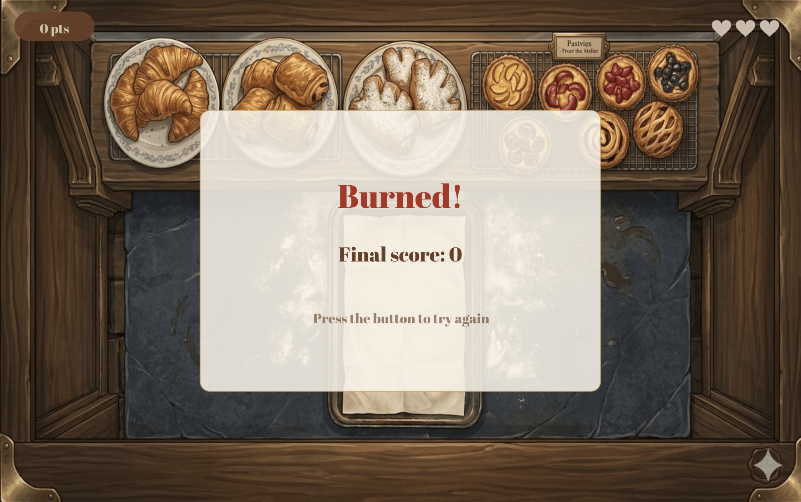
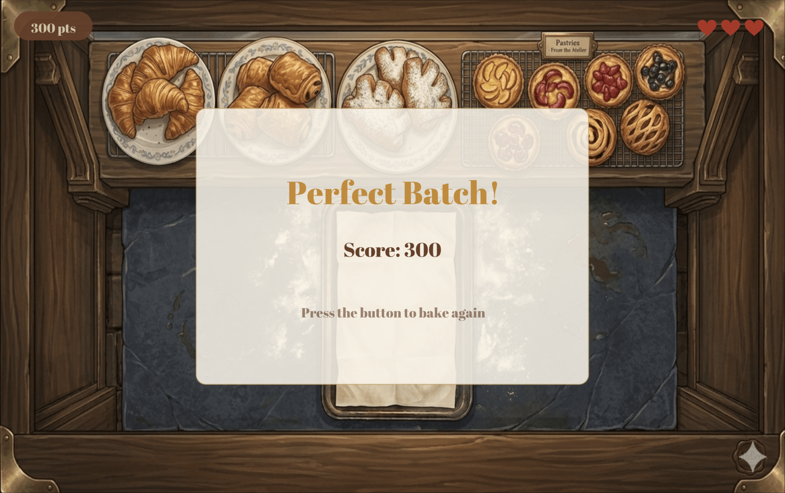
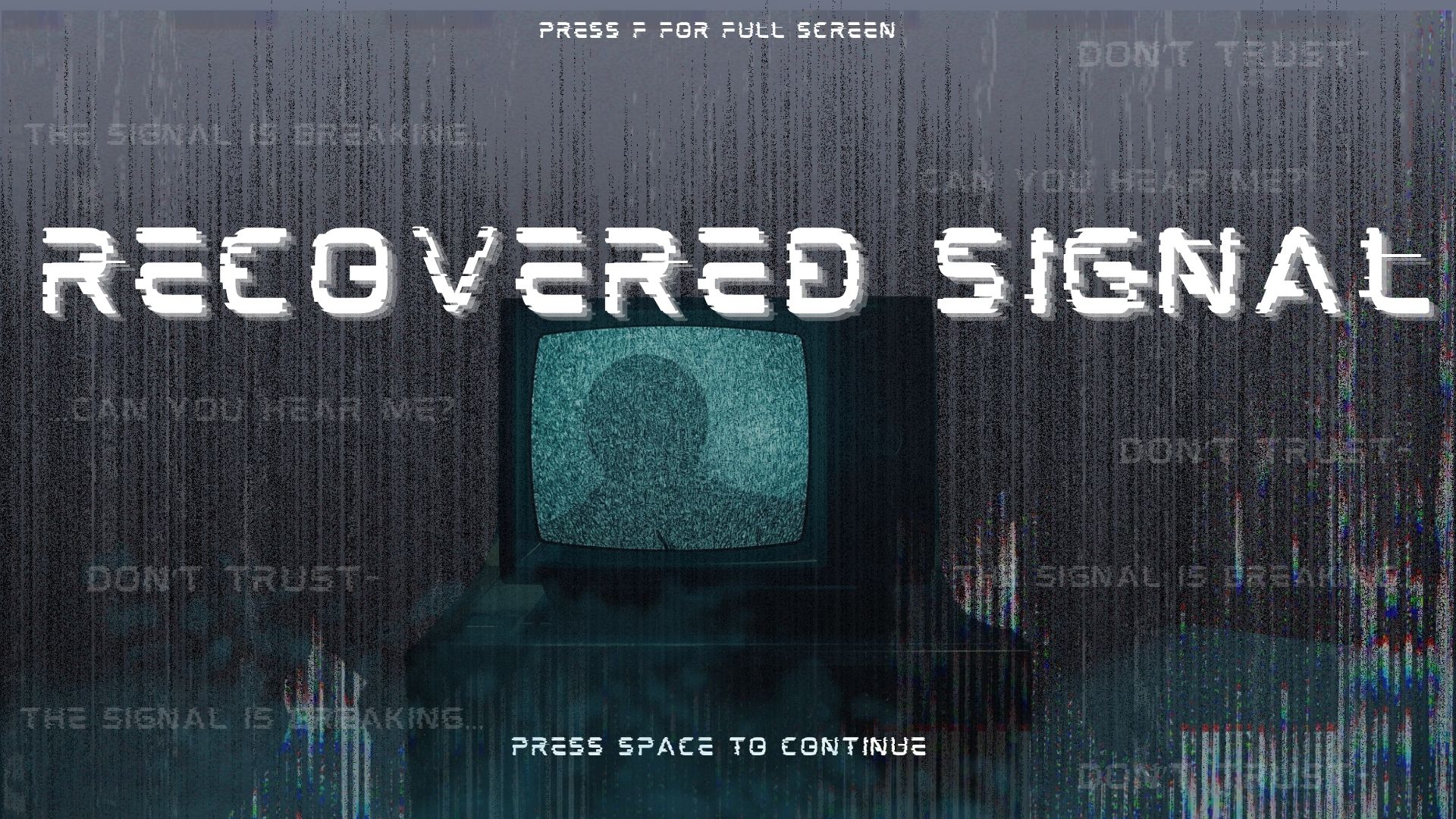
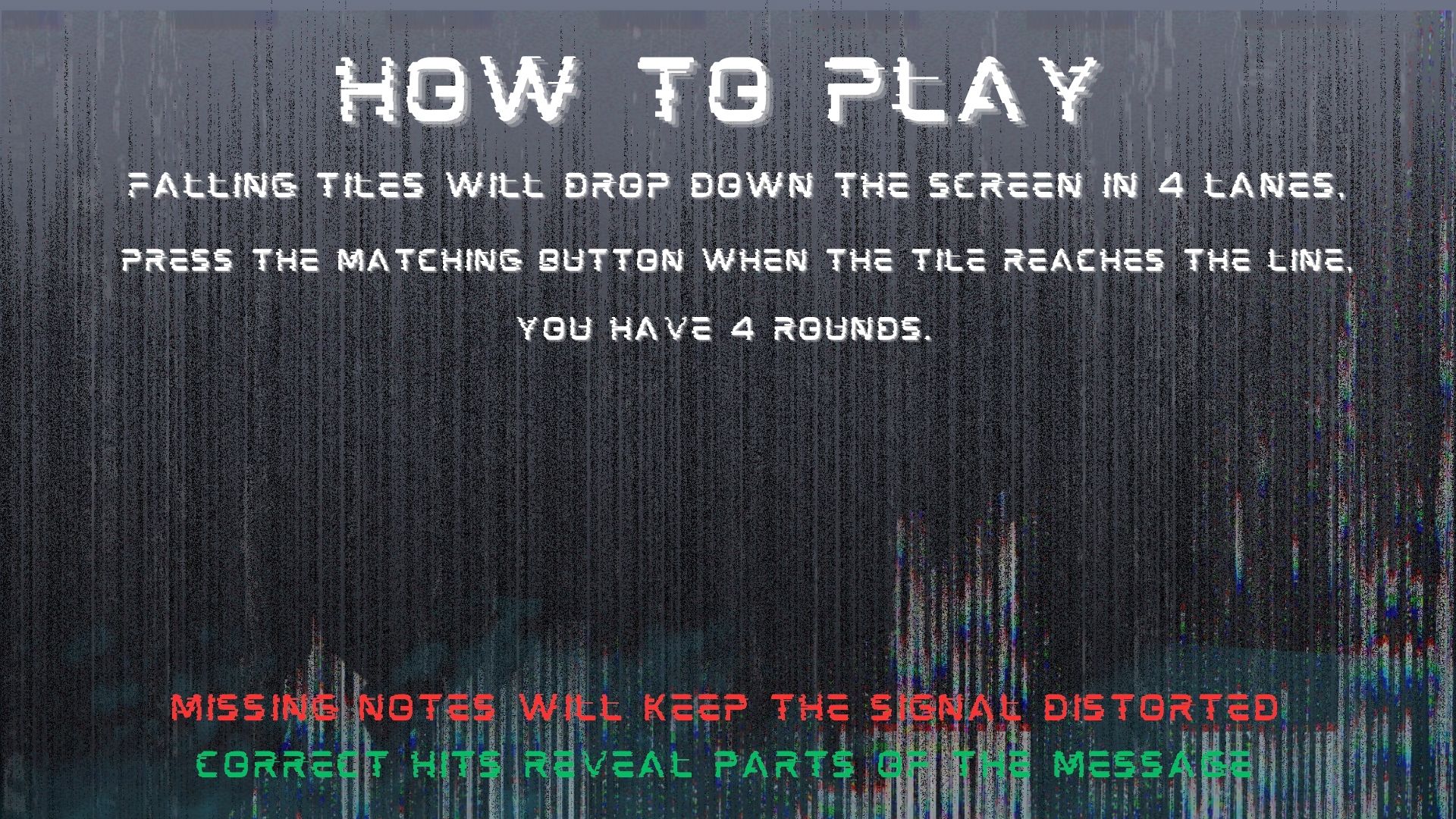
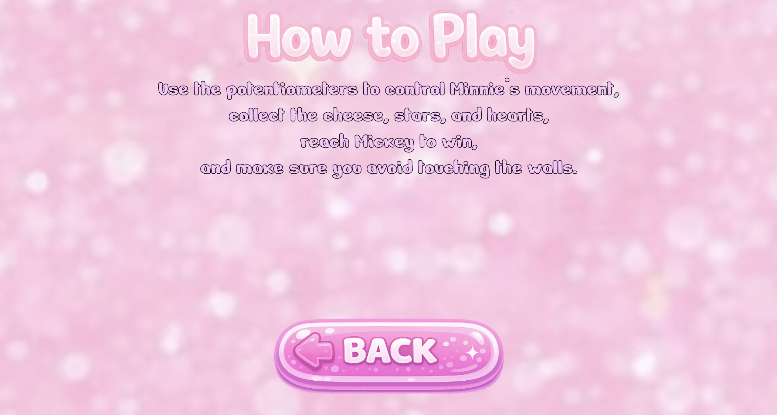
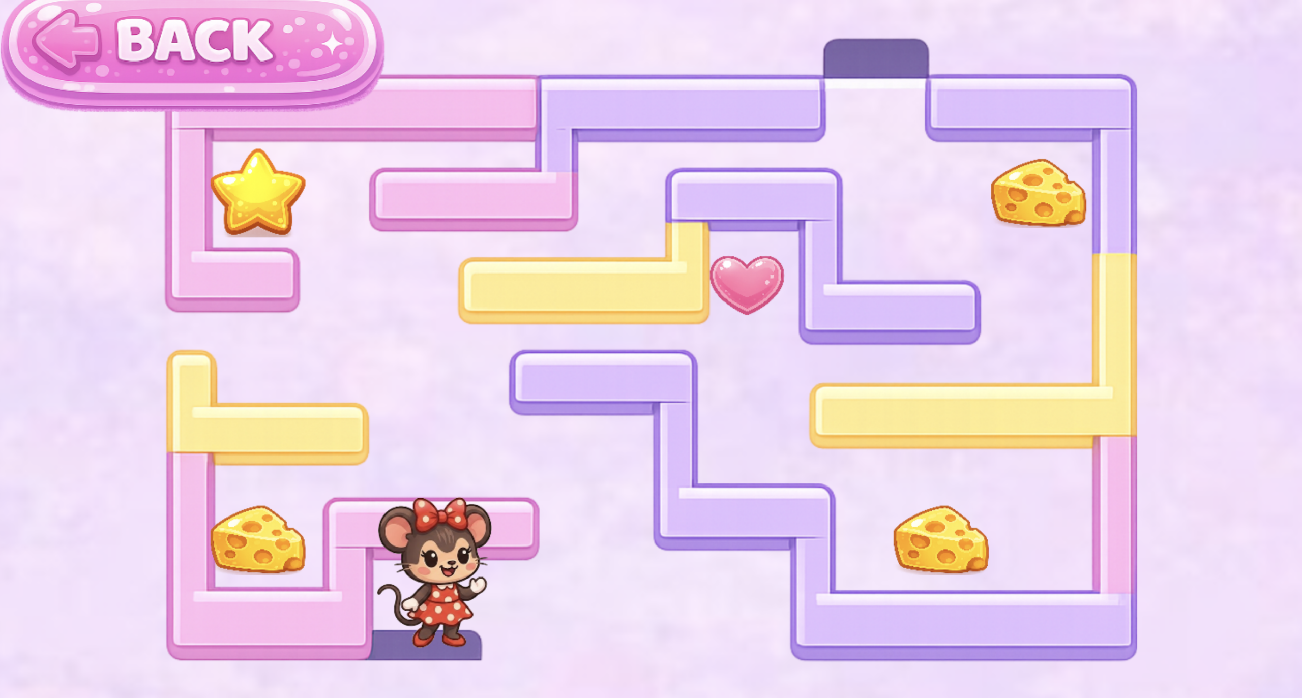
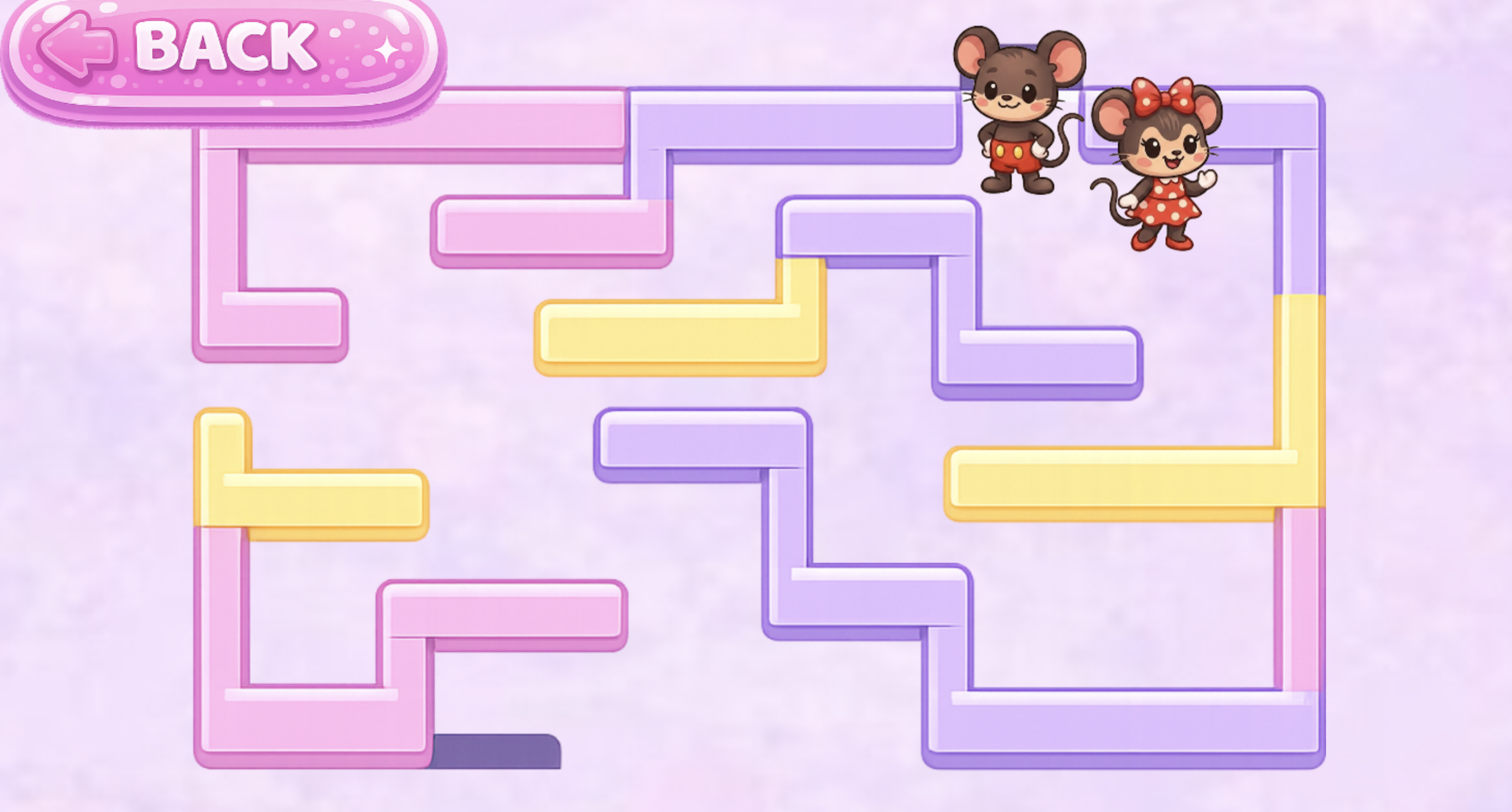
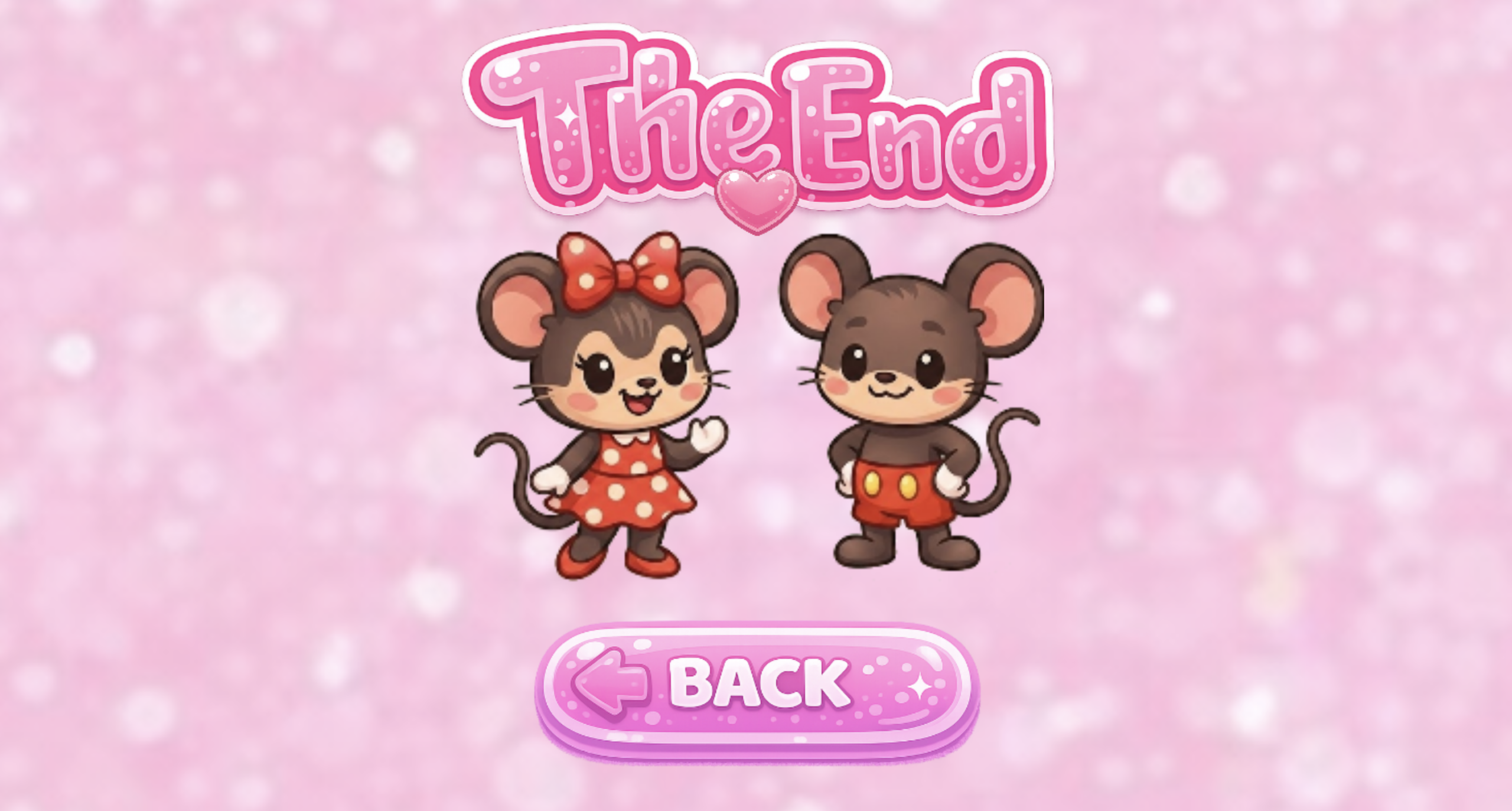
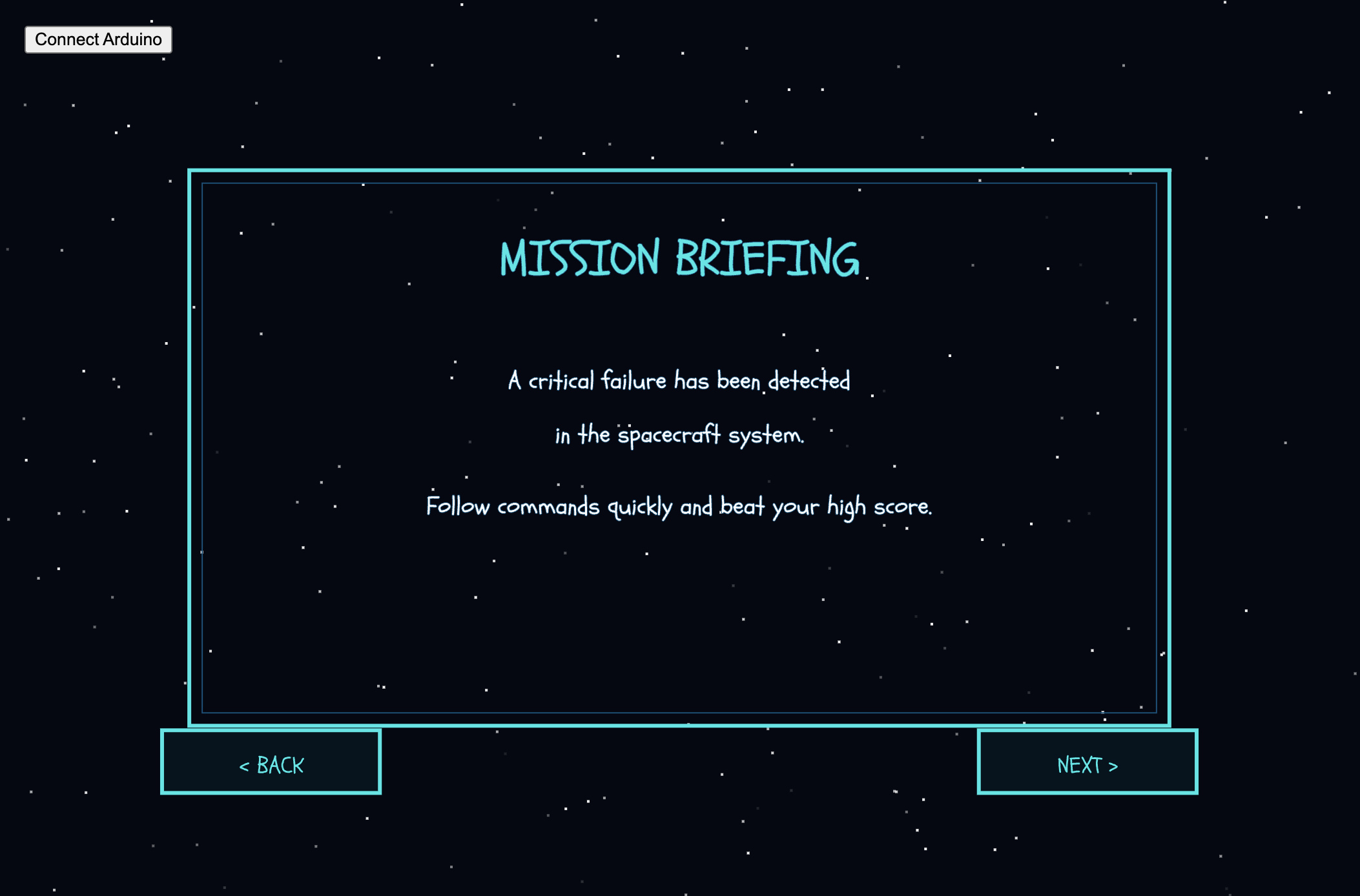
Here are some images from my p5 sketch. All of these screens and interactions can also be fully experienced directly through the embedded p5 sketch:

Another major challenge was aligning and displaying the sprite sheets correctly inside the p5 sketch. Some frames would shift position, go off screen, or get cropped incorrectly during the animations. At some points, multiple sprites would appear at once, while other frames looked unaligned or partially cropped. To solve this, I watched tutorials, reviewed references, and experimented with frame sizing, cropping, and scaling until I fully understood how sprite sheets and frame positioning worked within my code. This process helped me improve the consistency and quality of the animations.
// Frame widths based on each exported sprite sheet
  getFrameWidth() {
    if (this.name === "tamper") return 1040 / 7;
    if (this.name === "grinder") return 989 / 7;
    if (this.name === "coffee") return 612 / 6;
    if (this.name === "steamer") return 774 / 8;
  }

// Select the current frame from the sprite sheet
    let cropX = round(this.frame * frameW);
    let cropY = 0;
    let cropW = round(frameW);
    let cropH = frameH;

    let spriteW = cropW * scaleFactor;
    let spriteH = frameH * scaleFactor;

    // Center sprite on screen
    let spriteX = width / 2 - spriteW / 2;
    let spriteY = height / 2 - spriteH / 2;

    // Tamper sprite sheet needed slight position adjustment
    if (this.name === "tamper") {
      spriteX += 80;
      spriteY += 20;
    }
Note: For the frame widths, I used another website called Photopea to calculate how many pixels wide each sprite sheet was, then divided that value by the number of frames to calculate the width of each individual frame. I then continued experimenting and adjusting the positioning and scaling until the animations appeared more consistent on screen.
The tamper action also has an individual adjustment at the end to slightly change its X and Y position, since that specific sprite sheet frames were more visually unaligned compared to the others.
Implementing Feedback:
During the first user testing drafts, I had a user try my project and noticed two important improvements that I should make, which I then implemented into the final version.
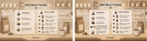
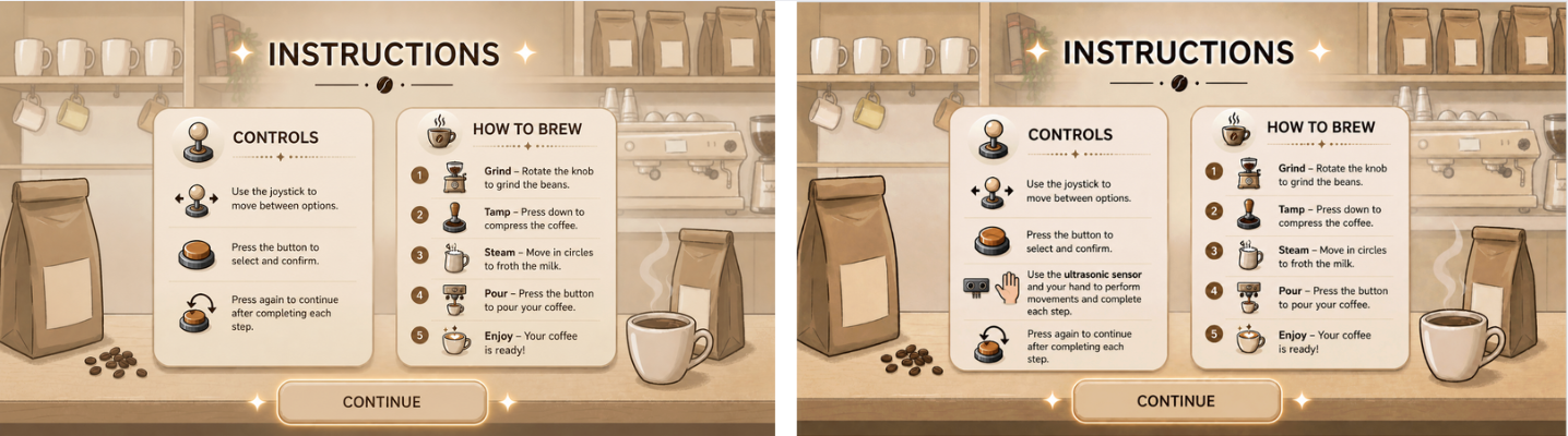
First, I added the ultrasonic sensor to the instructions page so the user would clearly understand where to place their hand and how to interact with the movement actions. Here is the before and after of the instructions page:
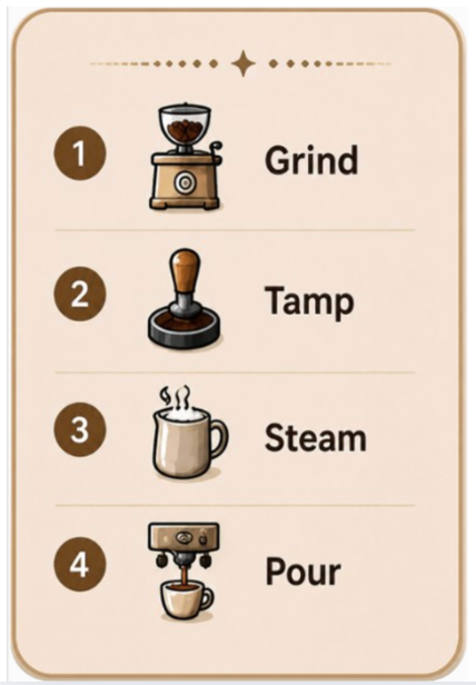
Second, I added a short step guide on the main setup screen so the user could quickly remember the coffee-making order in case they forgot the steps during the interaction. I created the mini guide visually, then coded it to only appear on the main setup screen and adjusted its position to fit naturally within the interface. Here is the mini guide and its code:

// Display mini guide only on the main setup screen
    image(miniGuide, width * 0, height * 0, width * 0.2, height * 0.35);
  } else if (state === "action") {
    getCurrentAction().display(bg);
  } else if (state === "end") {
    endScreen.display();
  }
}
Areas for future improvement:
Overall, I feel very satisfied with my final result, and I am proud of myself for making my idea work, especially because it was much more challenging than I initially expected. However, there are still areas that could be improved.
I think I could make the experience feel even more realistic by creating longer and more detailed sprite sheets with smoother movement to better represent the live coffee-making actions. I would also like to improve the physical setup by creating a more visually appealing coffee machine model and refining the overall presentation of the interaction.
Since I struggled a lot with the sprite sheets during this project, I think learning how to manually create and align them myself in the future would make it much easier to keep the animations more stable and consistent. It would also give me more control over the positioning, scaling, and overall quality of the animations.
For the future, I would love to create more simulations and interactive ideas using communication between p5 sketches and Arduino. I would also like to explore something more game-based to make the experience even more exciting, such as a café challenge game where the user has to prepare and serve orders for customers. I could even expand the idea further into a full restaurant simulation with multiple menu options and interactions.
Resources:
Arduino:
For my Arduino code, I mostly used the templates we were given in class to understand the structure, along with the official Arduino references to understand specific functions and actions I needed:
https://docs.arduino.cc/language-reference/en/functions/digital-io/pinMode/
https://docs.arduino.cc/language-reference/en/variables/constants/inputOutputPullup/
https://docs.arduino.cc/language-reference/en/variables/data-types/unsignedLong/
https://docs.arduino.cc/language-reference/en/variables/data-types/bool/
I also watched some tutorials for additional understanding:
https://youtu.be/KGwtit2bFyo?si=Fyh10tn7at7zFYyo https://youtu.be/vo7SbVhW3pE?si=PoRPErpxfsdc1cs5
P5:
For the p5 code, I mostly looked back at our lecture slides and what we covered in class, and I also referred to some of my previous sketches. I used the official p5 references to review and better understand specific commands:
https://p5js.org/reference/p5/image/
https://p5js.org/reference/p5/floor/
http://p5js.org/reference/p5/constrain/
I also watched multiple tutorials to help me achieve the visual actions and sprite animations I wanted:
https://youtu.be/lT_q-ylhML0?si=pfqHTvgWGA_ONRQn https://youtu.be/i2C1hrJMwz0?si=QiOL9T3fHeHro-4e
https://youtu.be/Pn1g1wjxl_0?si=YPGGnEIVbr6oa3yt
Connections:
For the Arduino and p5 communication, I mainly referred to the serial communication slides we covered in class, along with these videos for additional understanding:
https://youtu.be/MtO1nDoM41Y?si=KiDzo6fA5sIav8xj https://youtu.be/MHJ6KpgE7j4?si=lm94nLPvr4QUqhRO
Referencing of use of AI tools:
I also used AI for support once I faced issues with my code. One major example was when I had trouble with the sprite sheets, as mentioned above, since they would completely go off screen or get cropped during some frames no matter what I tried. After reviewing references and tutorials, AI specifically explained how sprite sheets worked in my context, and that the main issue was related to cropping and frame sizing within the sprite sheets. It guided me through the process of fixing and improving them.
After experimenting with frame calculations and sprite sizing myself, AI further helped explain how sprite sheet cropping, scaling, and frame positioning worked in my specific setup. AI further helped explain how sprite sheets function using total pixels divided by frames, and how functions such as getScaleFactor() could help visually adjust and balance each animation more consistently on screen.
Most of the actions improved after that except for the tamp action. I explained the issue I was still facing, and it walked me through it, leading me to use a specific if statement for the tamping action to adjust its X and Y position separately from the other animations. Here:
// Tamper sprite sheet needed slight position adjustment
    if (this.name === "tamper") {
      spriteX += 80;
      spriteY += 20;
    }
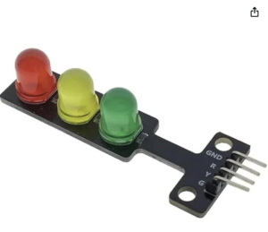
I also used AI assistance while working with the RGB LED module, since I could not find tutorials that matched the exact LED model and interaction style I wanted. It helped me understand how the 4-pin RGB LED worked in my specific setup, how to wire it correctly with Arduino output pins, and how to match the LED colors with the p5 states through serial communication. This is the one I used:
I also used AI to help generate the visuals for my project. I described the exact theme, colors, layout, and style I wanted, then kept refining each image until it matched my vision. This was mainly used for the instructions page, setup screen, and the detailed images for each step. I specifically directed what elements and style I wanted included in each visual.
In addition, I used AI to help create the sprite sheets because I could not find ready-made ones that matched the specific aesthetic and coffee-making actions I wanted for my project.

 sical board it
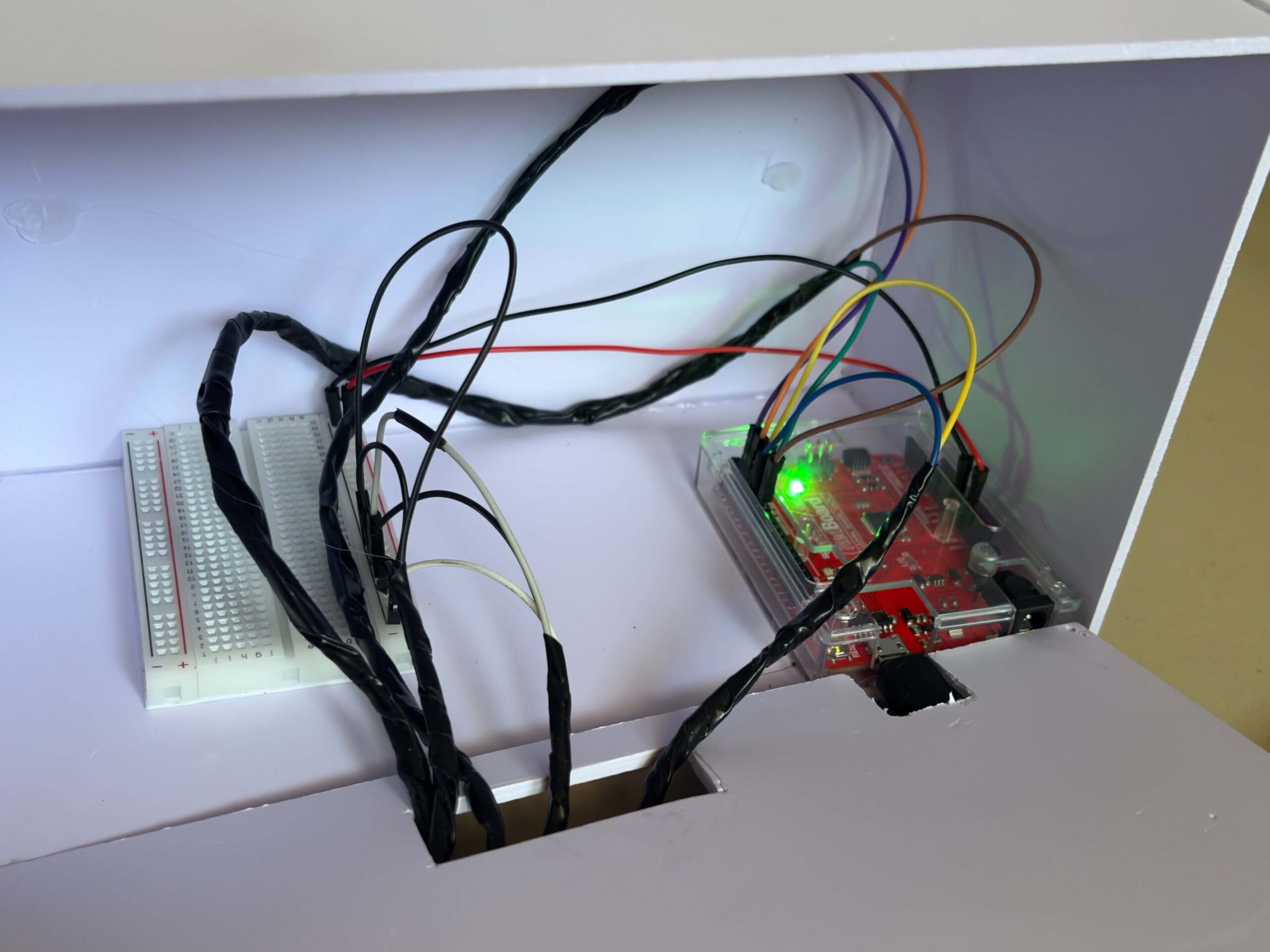


 •
•