Your concept
For this assignment, I wanted to explore the switch that comes with our kit. Till now, I had only used the buttons as a digital sensor, and I wanted something that can allow the user to turn on/off the buzzer without needing to press on it continuously. I also wanted to use the potentiometer to explore how I can reduce and increase the volume of the buzzer.
Hence, the circuit I ended up with includes all these elements. I wasn’t sure how to go about making my own melodies, especially with no music experience. So I referred to this GitHub repo that included many popular songs, and then edited the melody to only play the chorus of Hymn for the Weekend by Coldplay.
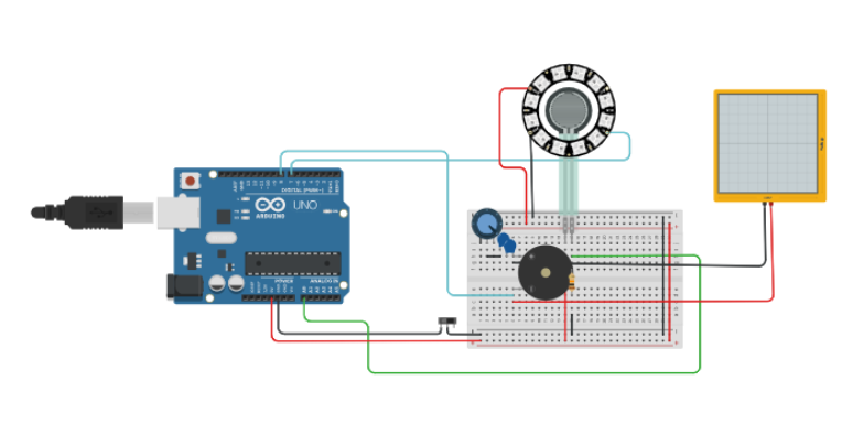
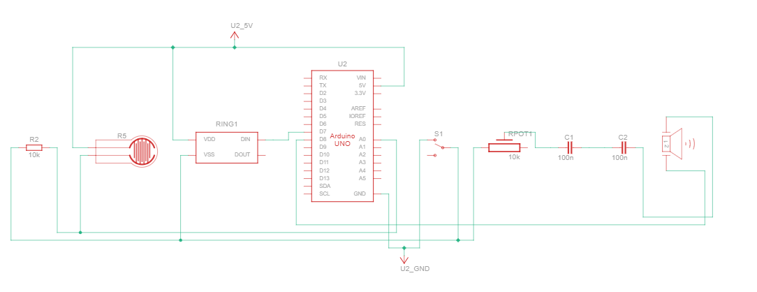
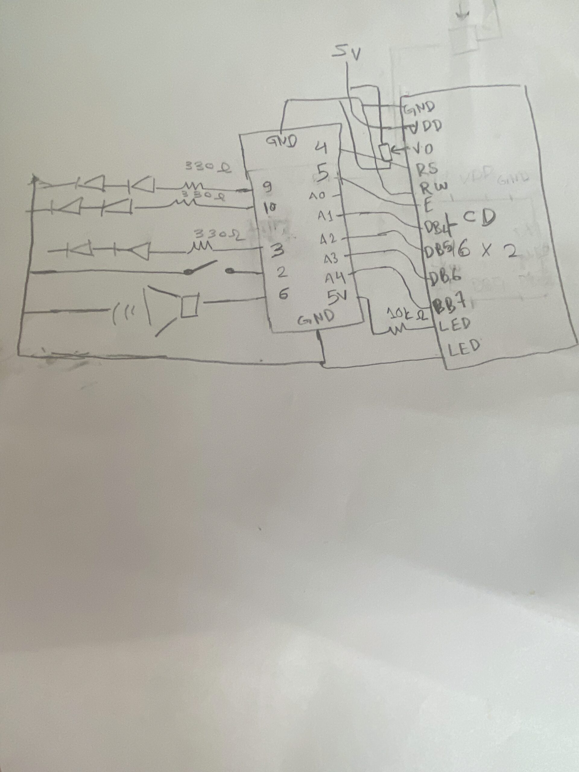
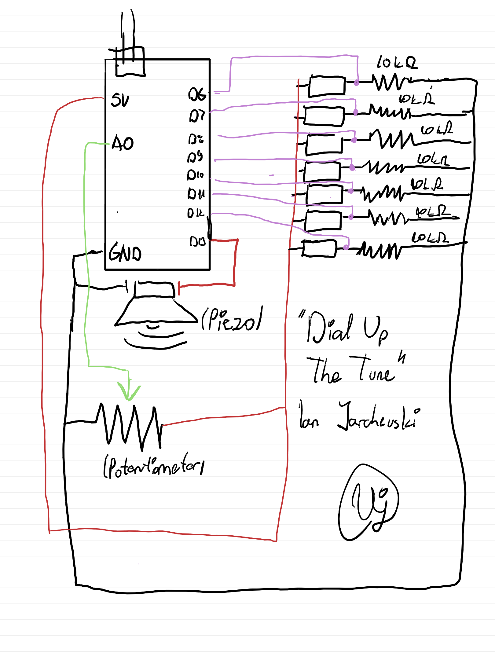
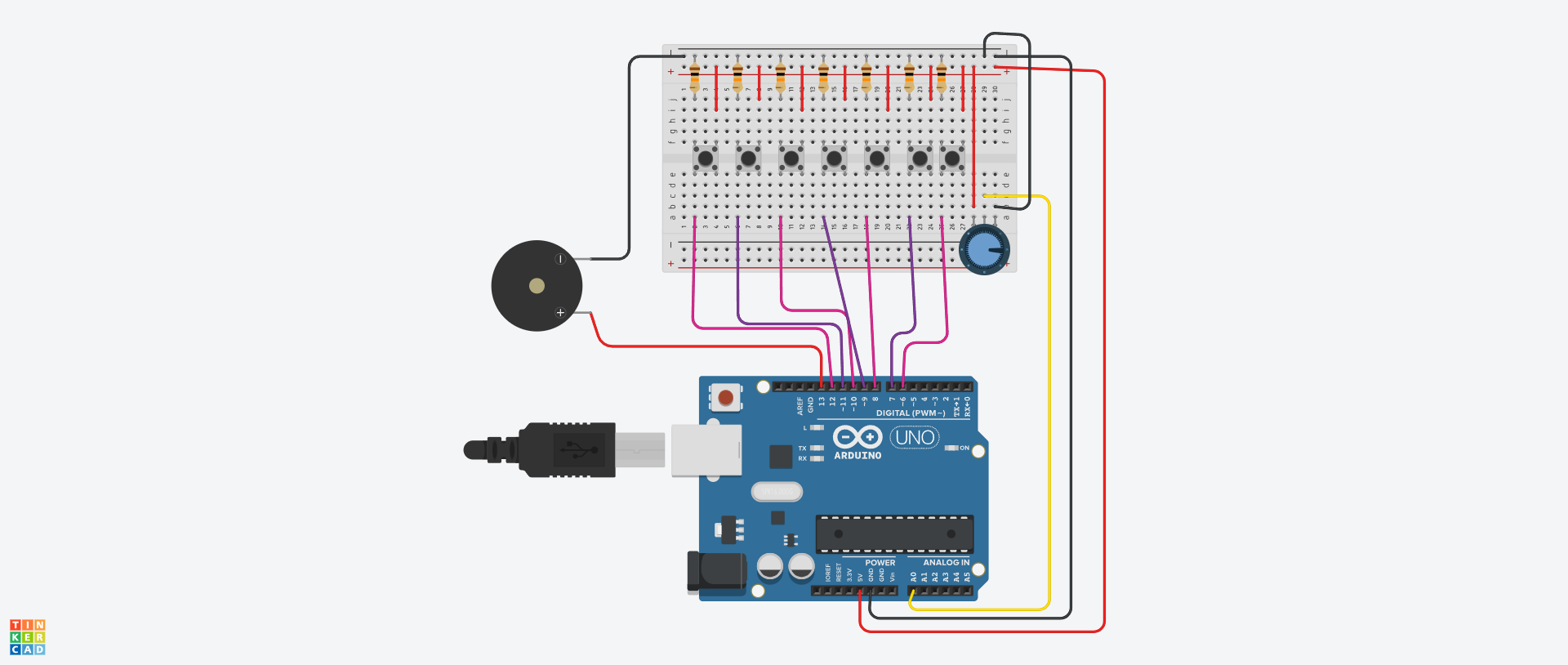
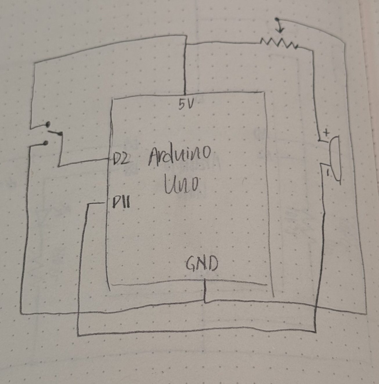
Schematic & Circuit
Video: IMG_8249
Code
#include "pitches.h"

const int buzzerPin = 10;
const int switchPin = 2;

int switchState;

int melody[] = {
  NOTE_DS5, NOTE_D5, NOTE_DS5, NOTE_C5, REST,
  NOTE_DS5, NOTE_D5, REST,
  NOTE_F5, NOTE_DS5, REST,
  NOTE_DS5, NOTE_D5, NOTE_DS5, NOTE_C5, REST,
  NOTE_DS5, NOTE_D5, REST,
  NOTE_F5, NOTE_DS5, REST,
  NOTE_DS5, NOTE_D5, NOTE_DS5, NOTE_C5, REST,
  NOTE_DS5, NOTE_D5, REST,
  NOTE_F5, NOTE_DS5, REST,
  NOTE_AS4, NOTE_C5, NOTE_AS5, NOTE_GS5, NOTE_G5, NOTE_G5,
};

int durations[] = {
  4, 4, 4, 2, 4,
  4, 2, 4,
  4, 2, 2,
  4, 4, 4, 2, 4,
  4, 2, 4,
  4, 2, 2,
  4, 4, 4, 2, 4,
  4, 2, 4,
  4, 2, 2,
  4, 4, 4, 2, 2, 1,
};

void setup() {
  pinMode(buzzerPin, OUTPUT);
  pinMode(switchPin, INPUT_PULLUP);
  pinMode(LED_BUILTIN, OUTPUT);
}

void loop() {

  switchState = digitalRead(switchPin);

  if (switchState == HIGH) {
    int size = sizeof(durations) / sizeof(int);

    for (int note = 0; note < size; note++) {
      // re-reads switch at every note
      switchState = digitalRead(switchPin);
      if (switchState == LOW) {
          noTone(buzzerPin);
          // digitalWrite(LED_BUILTIN, LOW); // used to debug
          break; // exit the loop immediately
    }

    // to calculate the note duration, take one second divided by the note type.
    int duration = 1000 / durations[note];
    tone(buzzerPin, melody[note], duration);

    // to distinguish the notes, set a minimum time between them.
    int pauseBetweenNotes = duration * 1.30;
    delay(pauseBetweenNotes);
    }
    // digitalWrite(LED_BUILTIN, HIGH);
  }
  else if (switchState == LOW) {
    noTone(buzzerPin);
    // digitalWrite(LED_BUILTIN, LOW);
  }

}
Code I’m proud of
if (switchState == HIGH) {
    int size = sizeof(durations) / sizeof(int);

    for (int note = 0; note < size; note++) {
      // re-reads switch at every note
      switchState = digitalRead(switchPin);
      if (switchState == LOW) {
          noTone(buzzerPin);
          // digitalWrite(LED_BUILTIN, LOW); // used to debug
          break; // exit the loop immediately
    }
I’m proud of this specific section of code as I was having trouble with ensuring that when the switch is in LOW state, the buzzer actually turns off. Initally, I didn’t have the code to check the switchState within the for loop for the notes. So, the buzzer would never stop (unless the switch was already on LOW in the start). Eventually, I figured out that I need to check the switchState between each note to check if the user has changed the switch.
“How this was made” section explaining how the code was made and sources of media assets
To understand how to use the switch and connect it in my breadboard, I referred to this video: https://youtu.be/0ZXYRU9KPG8?si=vtY1plmUuqMY7i48. Through this video, I also understood how to write the code so that I can have the buzzer be silent when the switchState is changed and vice versa.
For the melody and generating the music, I referred to https://projecthub.arduino.cc/tmekinyan/playing-popular-songs-with-arduino-and-a-buzzer-546f4a and the GitHub repo above for the specific song that I wanted. I only edited the melody to play just the chorus section sicne the whole song was a bit too long, and honestly, my favorite part of this song is the chorus.
Reflection and ideas for future work or improvements
One possible improvement I thought of after finishing my circuit was adding buttons to switch between songs. I guess like a mini radio station. I think this is probably feasible with buttons but that can be plan for another time.