
I wanted to make a non-traditional music instrument that feels like a game the could be played around with for hours, although it is very simple. It contains different modes but not only does have audio feedbacks, but also visual feedback through the LCD Screen and LED lights. It reminds me of a very simplified and modest version of a music instrument attached to a pedal, which gives different music effects. The LCD screen showing the hertz and bpm reminds me of a pedal.
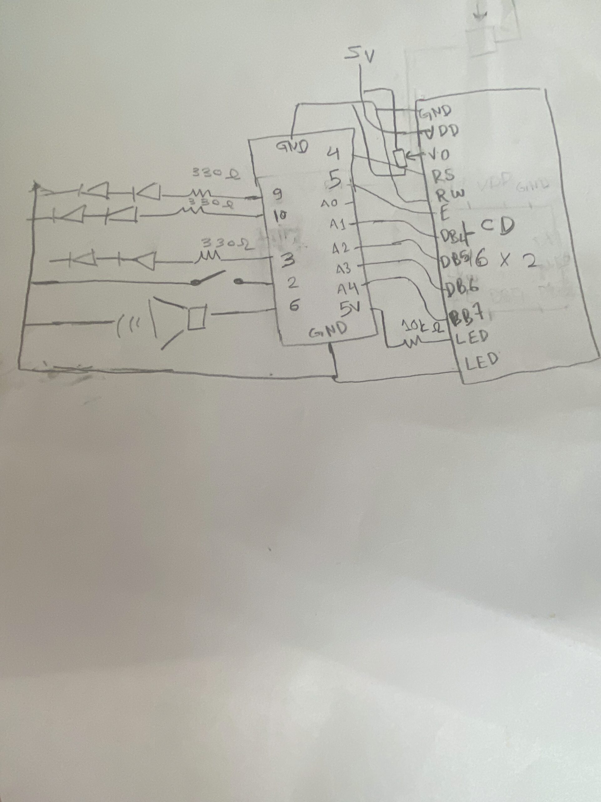
Hand-Drawn Schematics
Simulator
Again, I used the simulator to make sure I wouldn’t accidentally burn any components. When building a circuit, I take it step by step: I test the LEDs first—everything works great—then I add the photoresistor to control them and test again. After that, I add the piezo and repeat the process until I reach the LCD. I build each part in the simulation first, then immediately try it on the physical board. Which helped me realize the wires order connecting to the LCD display were flipped.

Video
How the code works
This code implements a light-controlled theremin with three distinct musical modes on Arduino, using an LDR as the primary input. The core structure reads the analog light value, smooths it with a 20-sample circular buffer, and maps it to different musical parameters depending on the active mode, Theremin, Scale, or Pac-Man. Mode 0 -Theremin- produces continuous pitch with glide and vibrato, generates a pulsing heartbeat animation on the LCD, and sweeps the RGB LED through a color gradient based on frequency. Mode 1 quantizes the light reading to 15 discrete C major notes, displays rainbow colors per note, and shows VU meter bars on the LCD using custom characters. Mode 2 maps light intensity to game speed, runs a side scrolling Pac-Man game on the LCD with ghosts and dots, and plays the classic sound. The button handling supports short-press to cycle modes and long-press to enter/exit sleep mode, while the RGB LED fades smoothly between target colors using a step-based transition. The LCD uses custom character sets loaded on-demand and tracks dirty rows to minimize redraws. A sinus lookup table generates vibrato and LED pulsing, and the audio output on the piezo uses tone() with frequency modulation. The code is organized into modular functions for each mode, character loading, LED fading, and button debouncing, with global state variables tracking everything from heart rate BPM to ghost positions.
Future improvements and Reflection
In the future, I would like to turn this prototype into a PCB and add more components and sensors to transform it into a more realistic musical instrument.
I struggled mainly with connecting the LCD screen. After working for long hours, I started to lose focus and couldn’t fully debug what was going wrong. Eventually, I realized that the two breadboards were not connected to each other, which fixed part of the issue. However, I still faced problems—the display would turn on but only showed strange white boxes.
I then checked the V0 pin on the LCD and noticed it was connected to the potentiometer but not properly connected to ground and power. After correcting the wiring and adjusting the potentiometer, the display sometimes still showed weird shapes and white boxes. I removed the LCD to inspect it and realized the wiring was flipped, since I was using the original LCD from the Arduino starter kit. The characters appeared as numbers at first, and some were reversed.
After fixing the wiring orientation and connections, everything started working properly.