Week 11 Ex03 Bi-Directional Communication

Github:

https://github.com/skyorachorn/Intro-to-IM/blob/5c35d686b16c8ad6965f1755d6dd0e0c786ab2c4/Ex03_Bi_Directional_Com.ino


Youtube:

https://youtu.be/9bqEiR_zGJM?si=Mm7S7kV4fjWl15sk

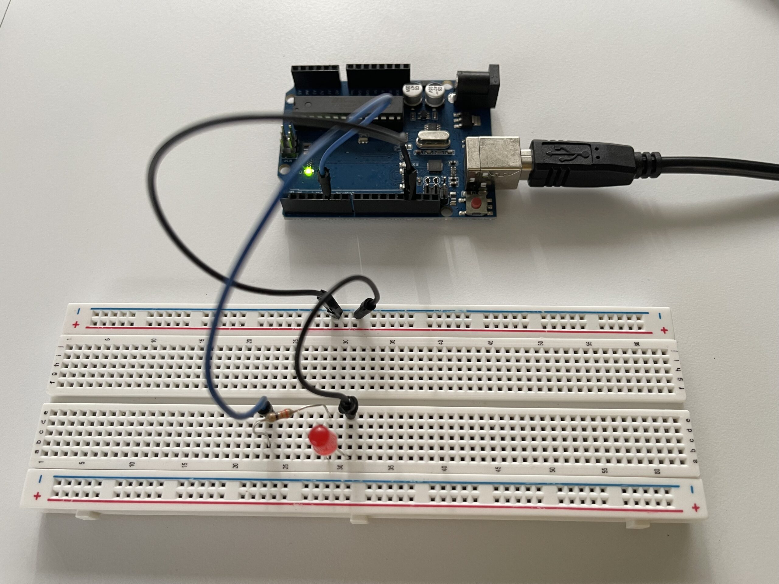
Circuit:
 

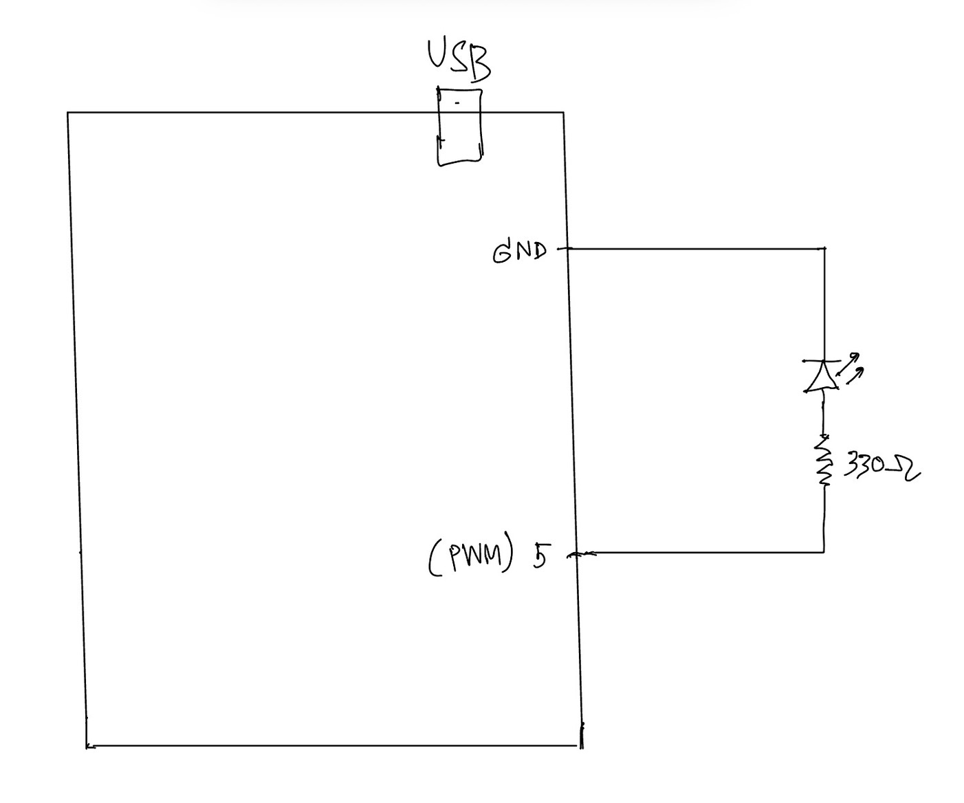
Hand Written Circuit:
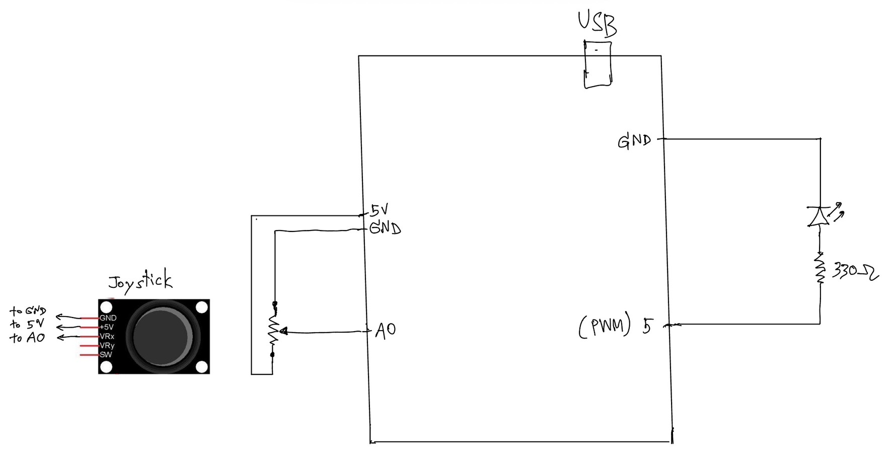
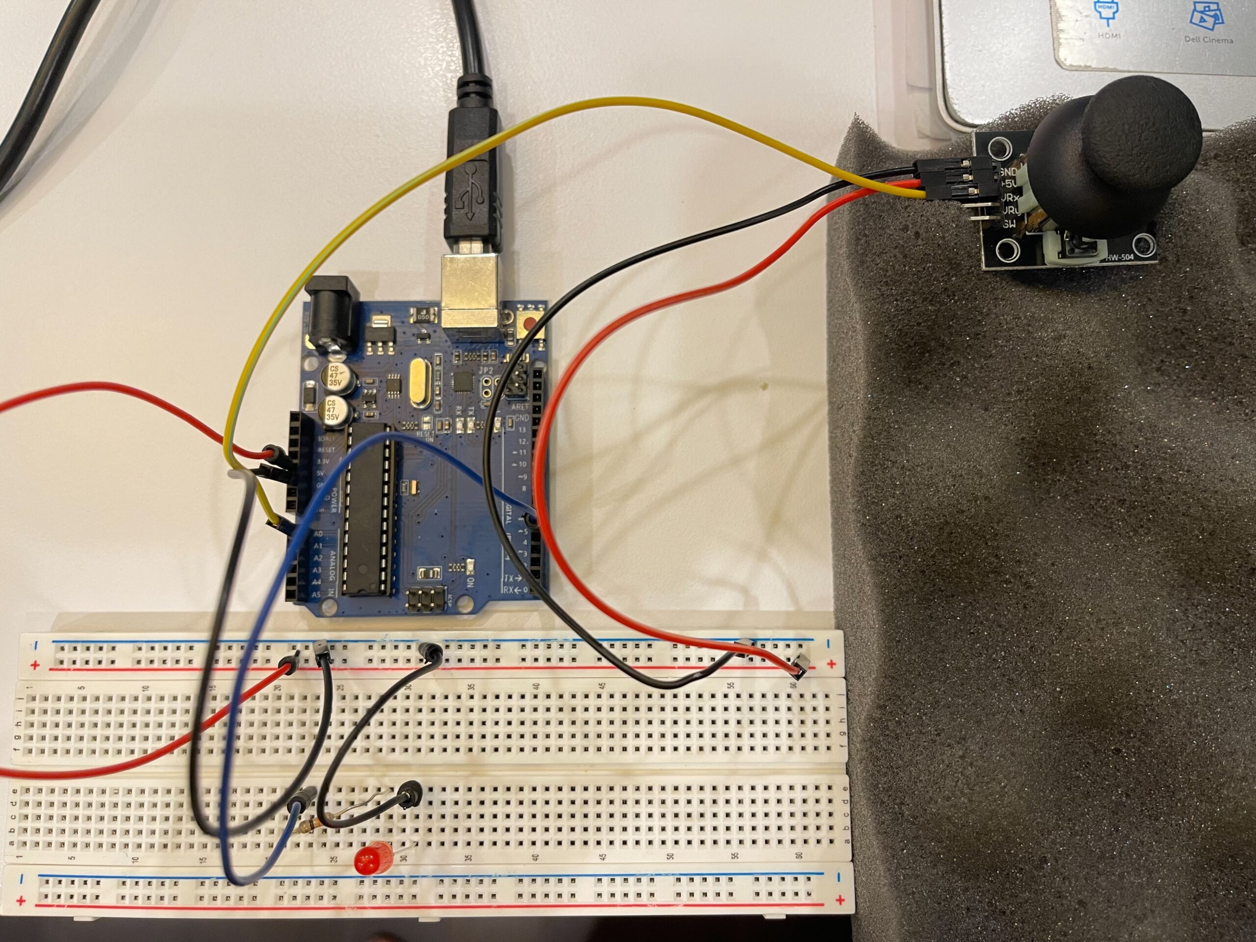
In this exercise, we extended our work from the previous tasks by implementing bi-directional communication between Arduino and p5.js. The goal was to use an analog sensor to control the wind force in a physics simulation, and at the same time send data back from p5 to Arduino to control an LED.

We started from the gravity and wind example provided in class and kept the structure mostly unchanged. Instead of using keyboard input to control the wind direction, we replaced it with a joystick connected to Arduino. The horizontal axis of the joystick was read using analogRead() and sent to p5 through serial communication.

On the p5 side, the incoming value was read using port.readUntil(“\n”), then converted into an integer. We mapped this value to a range between -1 and 1, which was used as the horizontal wind force. As a result, moving the joystick left or right directly influenced the movement of the ball in the simulation.

To complete the bi-directional interaction, we added a simple condition in p5 to detect when the ball bounces on the ground. Whenever a bounce occurs, p5 sends a value back to Arduino. On the Arduino side, this value is read using Serial.parseInt(), and the LED is turned on or off accordingly.

This allowed us to create a system where Arduino sends sensor data to p5, and p5 responds by sending control signals back to Arduino.

What We Learned:

* How to implement bi-directional serial communication
* How to use an analog sensor (joystick) to control a physics simulation
* How to send control signals from p5 back to Arduino
* How physical and digital systems can interact in both directions

Code I’m Proud Of:

One part we are particularly satisfied with is how the system detects a meaningful bounce and avoids triggering unnecessary signals.

p5.js (bounce detection + sending data)

let bounced = 0;
  let floorY = height - mass / 2;

  // bottom bounce
  if (position.y > floorY) {
    position.y = floorY;

    if (velocity.y > 2) {
      velocity.y *= -0.9;
      bounced = 1;
    } else {
      velocity.y = 0;
    }
  }

  // send LED state back to Arduino
  if (port.opened()) {
    port.write(bounced + "\n");
  }

This section is important because it defines what counts as a “real” bounce. By using a velocity threshold, we ensure that only stronger impacts trigger the LED, while small movements at the ground are ignored.

Arduino (receiving and controlling LED)

int ledState = Serial.parseInt();

    if (Serial.read() == '\n') {
      digitalWrite(ledPin, ledState);
    }

This part connects the digital signal from p5 to a physical output. It shows how a simple value sent through serial communication can directly control hardware.

Challenges:

One issue we encountered was that the LED flickered rapidly when the ball reached the ground. Even though the ball appeared to be at rest, the system continued to detect small movements due to gravity and drag.

At first, this made the LED stay on or flicker continuously, which was not the intended behavior.

To solve this, we introduced a simple velocity threshold. Instead of triggering a bounce whenever the ball touched the ground, we only considered it a valid bounce when the downward velocity was greater than a certain value. After testing, we found that using a condition of velocity.y > 2 provided a stable and clear result.

This helped us better understand how physics simulations can produce small continuous movements, and why additional conditions are sometimes needed to define meaningful events.

Future Improvements:

If we were to continue developing this project, we would consider:

* Adding a dead zone to the joystick to reduce unwanted drift
* Using both axes of the joystick to control more complex motion
* Adding more LEDs or outputs to represent different events
* Improving the visual feedback to better match the physical response


Reference:
https://youtu.be/6LkqhQ1-vJc?si=E_jhX4XUAnMQBCrY

https://youtu.be/pD2JUNUWJGU?si=xgiGR7X3Bhdkyi6W

Week 11 Ex02 P5 to Arduino Communication


Github:

https://github.com/skyorachorn/Intro-to-IM/blob/0f3767a9cc4fe21946d8b84a76a020a09abacbbd/Ex02_P5_to_Arduino_Com.ino


Youtube:

https://youtu.be/BT8Y9AafPIk?si=77WJciHPNwpz8n2J


Picture of Circuit:

Hand Written Diagram:

In this exercise, we explored serial communication in the opposite direction, from p5.js to Arduino. The main objective was to control the brightness of an LED on Arduino using an interaction created in p5.

We again started from the class example and kept the overall structure close to what was introduced by professor Aya. However, for this exercise, we simplified the communication so that p5 sends only one value instead of multiple values. This made it easier to focus on the main idea of sending data from the browser to Arduino.

On the p5 side, we used the p5.webserial library and the same button-based connection method as in the previous exercise. Once the serial connection is opened, p5 continuously sends a brightness value based on the horizontal position of the mouse. This value is mapped into a range between 0 and 255, which matches the range used by analogWrite() on Arduino.

On the Arduino side, we used Serial.parseInt() to read the incoming integer sent from p5. After checking for the newline character \n, the value is applied to an LED connected to a PWM pin. This allows the LED to gradually brighten or dim instead of simply turning on and off.

This exercise helped us better understand how p5 can be used not only to receive data from Arduino, but also to actively control physical outputs on the hardware side. Compared to Exercise 01, this made the communication feel more interactive because the browser was no longer only displaying data, but also sending instructions back to Arduino.

Through this process, we gained a clearer understanding of how serial data can be used to control physical output in real time, and how important it is for both the code structure and the wiring to match the intended behavior.

What We Learned:

* How to send data from p5.js to Arduino through serial communication
* How to use Serial.parseInt() on the Arduino side
* How to control LED brightness with analogWrite()
* How browser-based interaction can directly affect hardware output

Code I’m Proud Of:

One part we are particularly satisfied with is how the p5 sketch and Arduino sketch work together to control LED brightness in real time. This section clearly shows how a visual interaction in the browser becomes a physical output on the Arduino side.

p5.js (sending brightness value)

let brightness = int(map(mouseX, 0, width, 0, 255));
  brightness = constrain(brightness, 0, 255);

  // show the current value on screen
  fill(brightness);
  rect(100, 150, 200, 100);

  fill(0);
  textSize(16);
  text("Brightness: " + brightness, 120, 130);

  if (port.opened()) {
    port.write(brightness + "\n");
  }

This part is meaningful because it translates a simple mouse movement into a numerical value that can be understood by Arduino. It also helped us see how p5 can act as the controlling side of the communication.

Arduino (receiving + controlling LED)

int brightness = Serial.parseInt();

    if (Serial.read() == '\n') {
      analogWrite(ledPin, brightness);
    }

We found this section especially important because it shows how Arduino receives a value from p5, processes it, and immediately applies it to a physical output. In this case, the output is the LED brightness controlled through PWM.

Problems We Encountered:

One issue we encountered was that the LED did not appear to brighten or dim smoothly at first. Even though the value on the p5 side was clearly changing, the LED response did not look correct. After checking both the code and the circuit, we realized that the LED needed to be connected to a PWM pin in order for analogWrite() to work as expected. Once we moved the LED to the correct pin, the brightness control became much more visible.

Another thing we paid attention to was keeping the communication format simple. Since this exercise only required brightness control, we kept the message to a single value followed by a newline character. This made the program easier to understand and reduced confusion while testing.

Future Improvements:

If we were to continue developing this exercise, we would consider:

* Replacing mouse control with a more interesting p5 interaction, such as dragging, key presses, or etc.
* Adding multiple LEDs and sending more than one value from p5
* Expanding the system into bi-directional communication so Arduino could also send sensor data back to p5
* Improving the visual design in p5 so that the screen feedback more closely matches the physical LED behavior

Week 11 Ex01 Arduino to P5 Communication

Github:

https://github.com/skyorachorn/Intro-to-IM/blob/38f5a920179feadd602c862571956198fbb9e0cf/Ex01_Arduino_to_P5_Com.ino


Youtube:

https://youtu.be/dvRseX6c4VU?si=mKZLcT-Lm9T1LGMQ

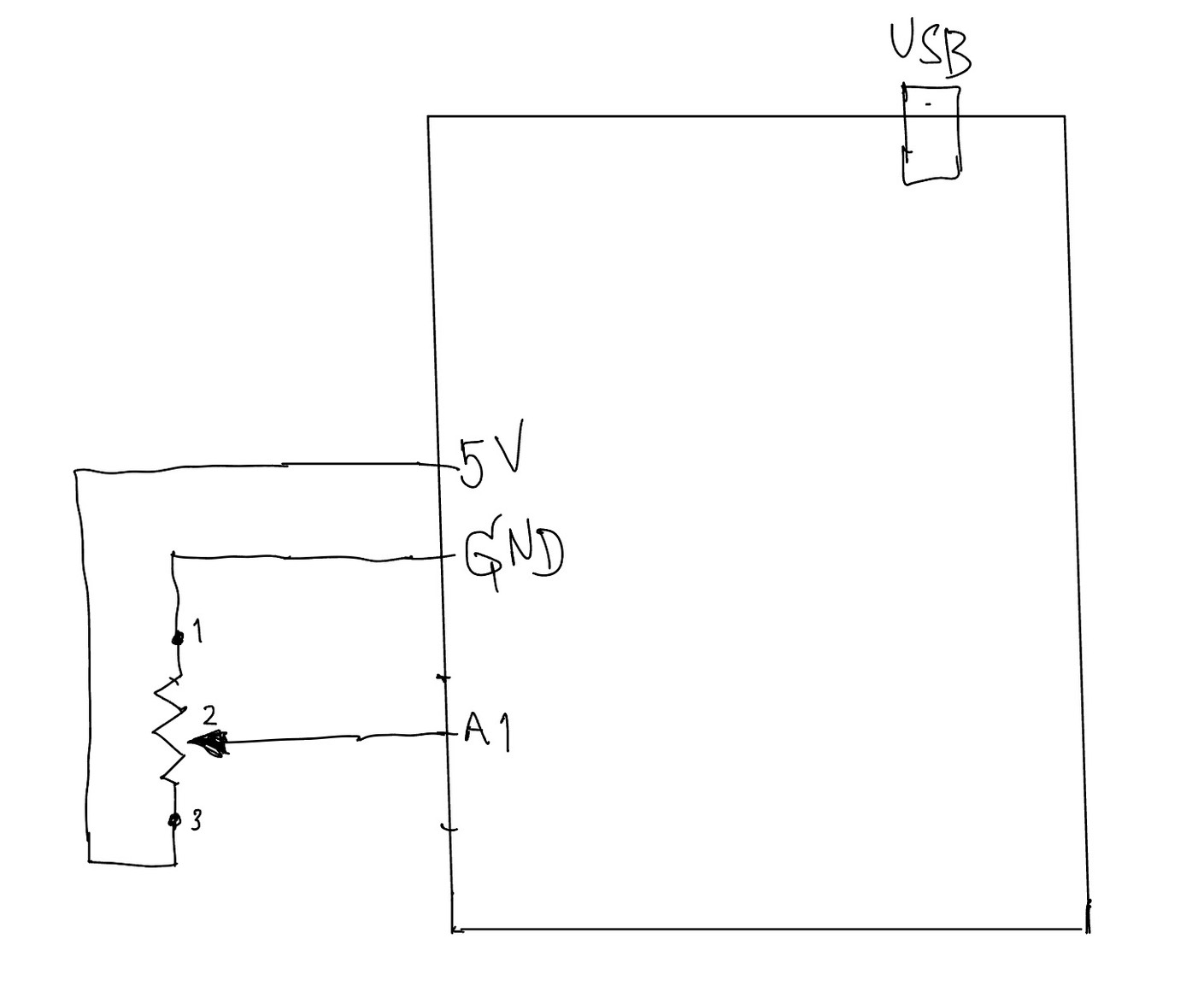
Handwritten Diagram:

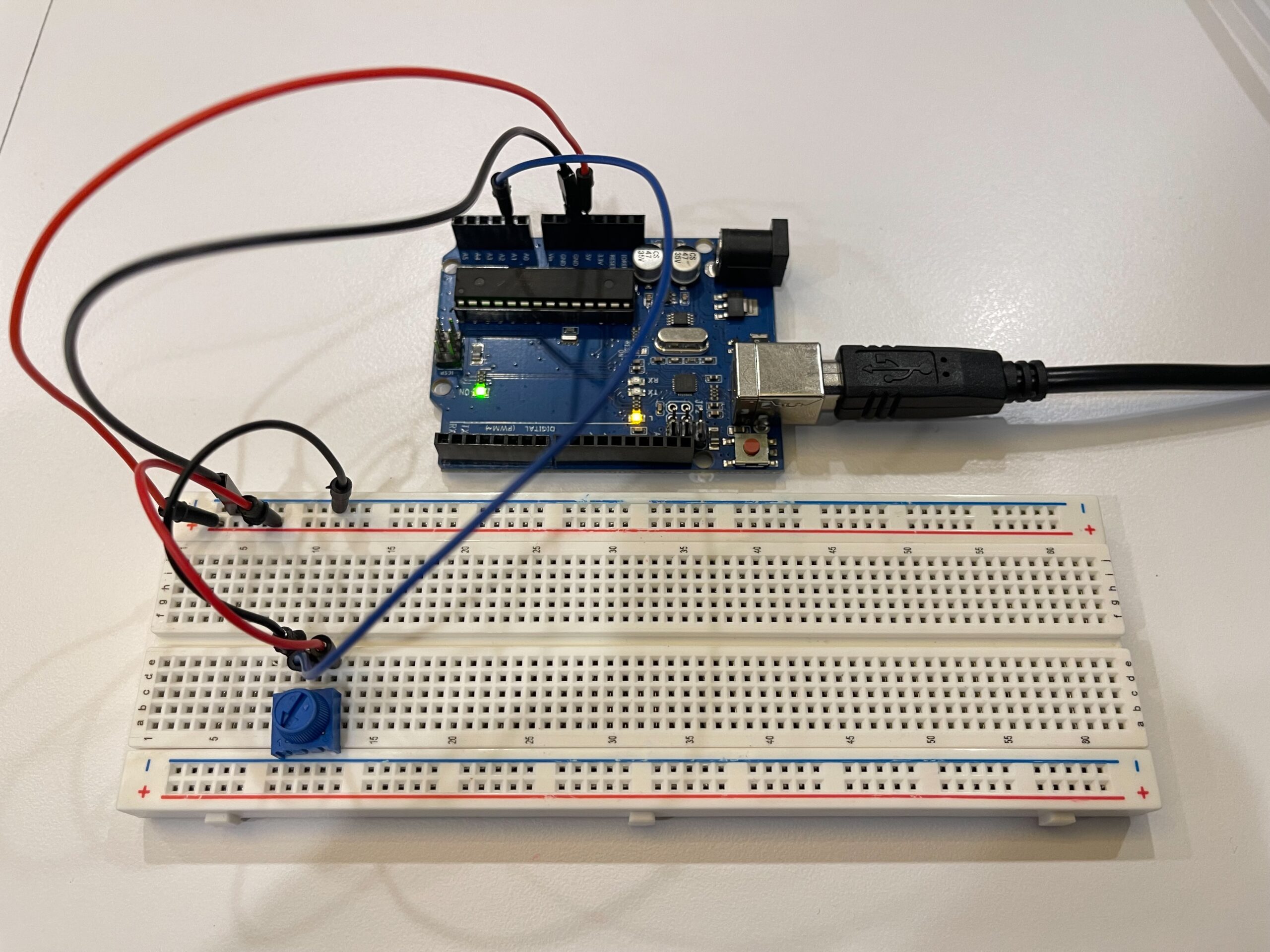
Picture of Circuit:

In this exercise, we explored serial communication between Arduino and p5.js. The main objective was to use a single sensor on Arduino and translate its input into visual movement in p5, specifically controlling an ellipse moving horizontally across the screen.

We began by following the example demonstrated in class and gradually adapted it to better understand the data flow. On the Arduino side, we used a potentiometer as an analog input. The sensor value (0–1023) was mapped to a smaller range (0–255) before being sent through the serial port using Serial.println(). This ensured that the data could be easily interpreted on the p5 side.

For p5.js, we adopted the structure introduced by professor Aya using the p5.webserial library. The connection process is handled through a button (connectBtn), and the serial port is opened using port.open(baudrate). This approach helped us clearly understand how communication between Arduino and the browser is initiated manually rather than automatically.

Inside the draw() loop, we used port.readUntil(“\n”) to read incoming serial data line by line. The received string is then cleaned and converted into a number using trim() and int(). We then used map() to convert this value into a position across the canvas width. As a result, the ellipse moves smoothly from left to right, and when the input value decreases, it naturally moves back from right to left, creating a responsive and continuous motion.

Through this process, we gained a clearer understanding of how physical input can directly influence digital visuals in real time. It also highlighted the importance of consistent data formatting and timing in serial communication.

What We Learned
• How to send analog data from Arduino using Serial.println()
• How to receive and interpret serial data in p5.js
• How to map sensor values into visual output
• How hardware and software can interact in real time

Code I’m Proud Of

One part we are particularly satisfied with is how the sensor data is processed and translated into visual movement. This section demonstrates how raw data from Arduino becomes meaningful interaction in p5.

int potentiometer = analogRead(A1);

 // map the value from 0-1023 to 0-255
 int mappedPotValue = map(potentiometer, 0, 1023, 0, 255);

 // send value to p5 as a string with newline
 Serial.println(mappedPotValue);

This part is important because it simplifies the raw sensor data into a range that is easier to use on the p5 side.

let str = port.readUntil("\n");

if (str.length > 0) {
  let val = int(trim(str));   // convert string → number

  // map value to screen position
  x = map(val, 0, 255, 0, width);
}

We found this section especially meaningful because it clearly shows the full pipeline: sensor → serial → processing → visual output.

Future Improvements

If we were to continue developing this project, we would consider:
• Using different sensors such as FSR or ultrasonic sensors for more dynamic interaction
• Adding smoothing to reduce noise in sensor readings
• Expanding the visuals to control multiple elements instead of a single ellipse
• Exploring bi-directional communication between Arduino and p5

Preliminary Concept for Final project

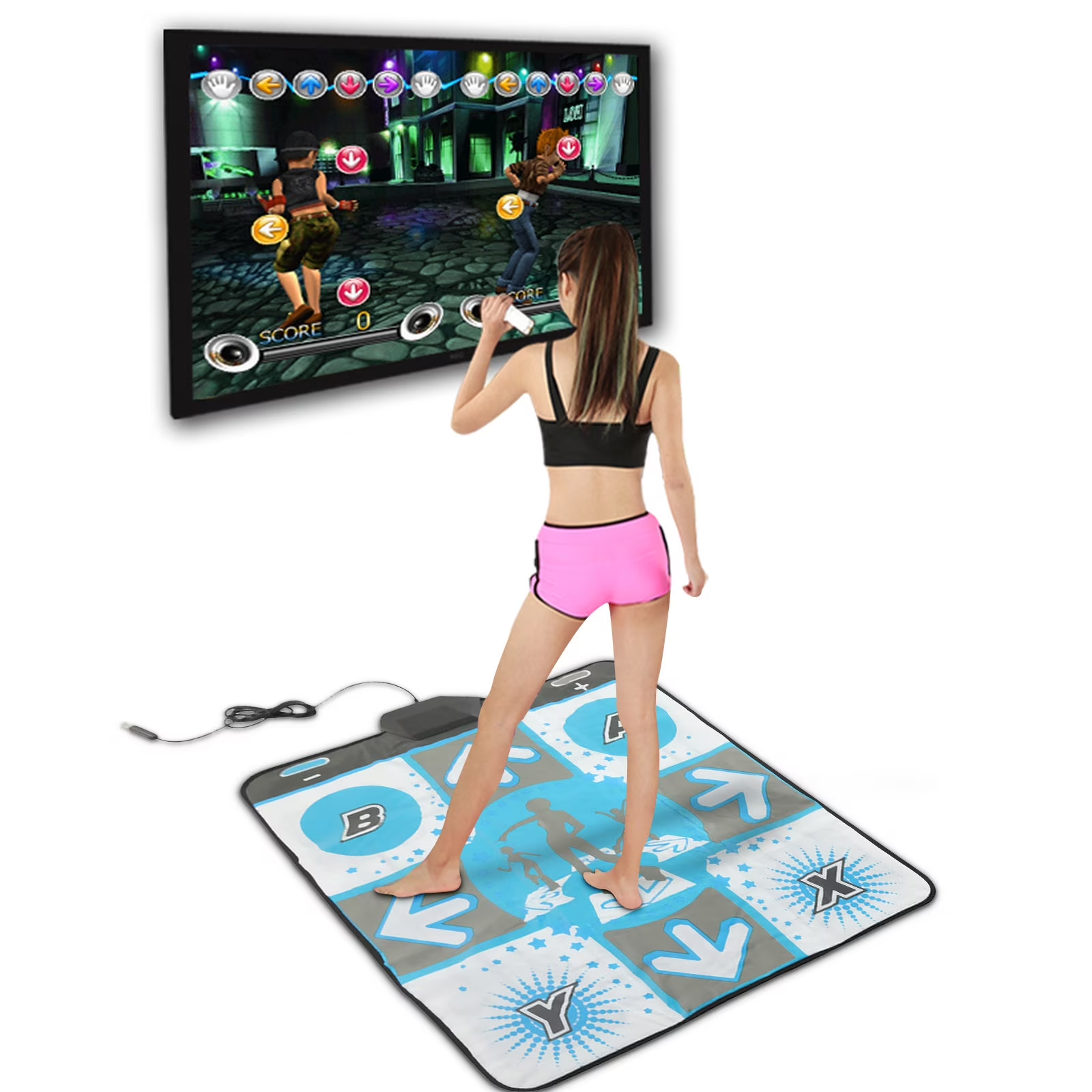
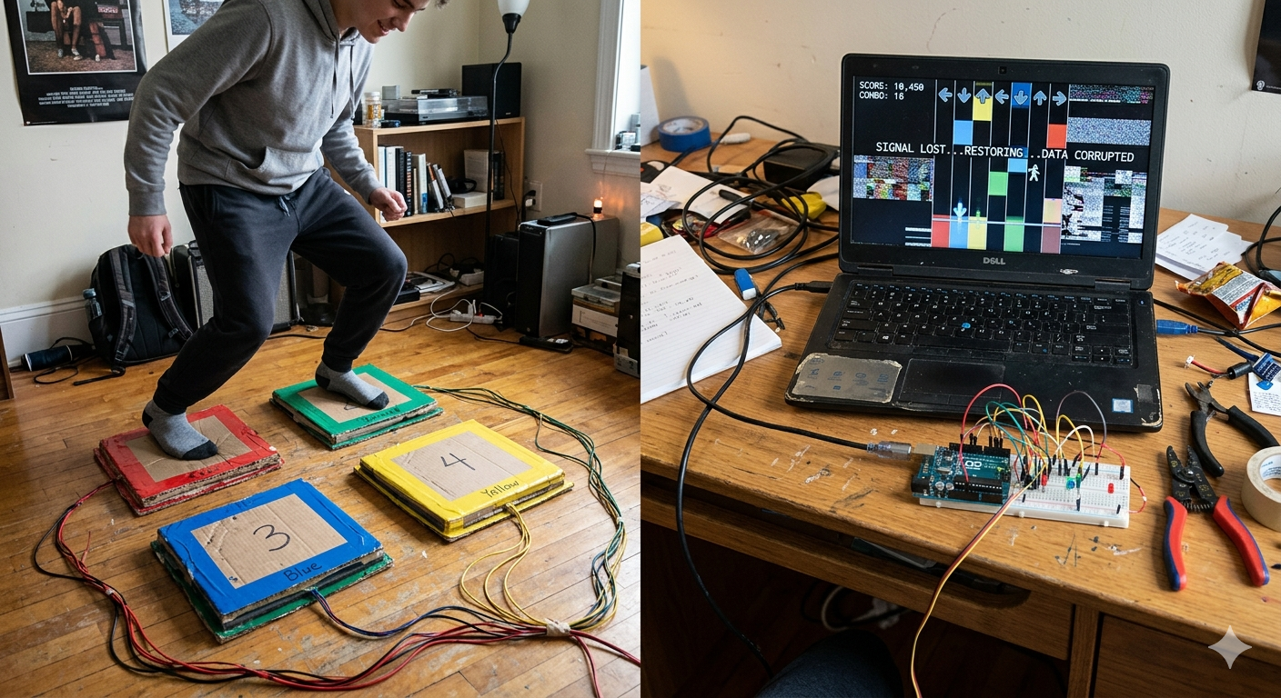
For my final project, I plan to create a physically interactive game where the player helps recover a corrupted digital signal of a story using their feet. The idea is inspired by games like Piano Tiles and Just Dance, but instead of simply playing for points, the user is actively uncovering a hidden message through their performance. By stepping on floor pads in time with visual cues, which I am thinking will be something similar to piano tiles and the Just Dance mat, the player will gradually restore a distorted audio/visual, which makes the experience into kind of like a mystery game:


I will use Arduino to capture physical input and P5 to handle the visual and audio output. On the floor, there will be 4 pads made from materials like cardboard or foam with conductive layers inside (or if there is a better sensor for this idea, I will use it). Each pad will act as a button connected to the Arduino, and when someone steps on a pad, the circuit is completed, and the Arduino sends that input data to p5 through the serial communication.

On the screen, p5 will display a rhythm like visuals with vertical lanes and falling tiles, like the piano tile game. The user must step on the pad at the correct time to match the falling tiles (which I am thinking will be color based, so it matches the floor tiles, and it is more obvious). For the visuals, it will initially appear distorted, with glitch effects, static, and broken text or images to represent a broken signal along with the tiles. As the player successfully hits notes on time, the system will respond immediately by reducing the distortion, sharpening visuals, and revealing fragments of audio or text of a story. I want it to gradually form a short narrative, such as a corrupted voicemail or like a partial conversation. But if the user misses notes, the distortion stays or I might back it to where it temporarily increases.

The game basically listens through the Arduino sensors, thinks by processing the timing and accuracy of the input in p5, and responds through changes in the visuals and sound. The player will then be paying attention and adjusting their movements based on the feedback they receive, especially when they start revealing more of the story.

I prompt Gemini AI to create a picture of the game, so you can get a vision of what I am trying to achieve:


COMPOSER OF THE OPERA – Final Project Proposal

Concept

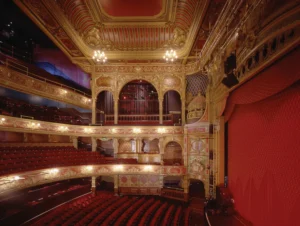
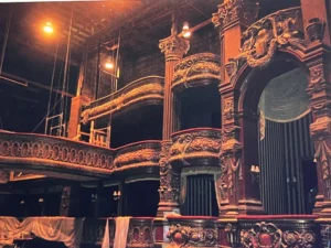
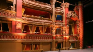
For my final project I had an idea inspired by the musical/film The Phantom of the Opera minus the obviously really weird creepy part. The idea is that you are a composer at an opera, and you have to be able to compose at least a good amount of the music while jump scares happen in the game.

I will be using my Arduino to create and connect the composer’s batons to my code and will connect the batons’ position to certain notes or volume or pitches or tempo (still unsure about what I want to do with this since its very complex) so when you try to move the sticks the position will translate to musical notes.

I will use p5 to code the design and the UI of the game and translate motion of the batons to actual events in the game.

I’m still unsure if I want to keep the jump scare component or if I want to keep it so that you just try to compose the music,  but for now this is the main concept I have in mind.

Visuals


Reading Reflection – Week 11

Reading Design Meets Disability made me think differently about how society treats disability devices. One part that stayed with me says that trying to hide these devices can show “a lack of self confidence that can communicate an implied shame.” This made sense to me because I believe disability devices should be shown proudly. There is nothing to hide, and people should feel free to embrace what makes them unique. The reading helped me understand that hiding something can sometimes send a negative message, even if people do not mean it that way.

Another idea that surprised me was how design for disability can inspire mainstream design. The text explains how the Eames leg splint influenced famous furniture. I never expected a medical object to shape everyday design. This showed me that disability centered design can be creative and important, not only functional.

The reading also changed how I think about the look of medical devices. When Aimee Mullins chooses “off the chart glamorous” prosthetics, it shows how fashion can help people feel confident. If I had to wear a hearing aid or prosthetic, I would want it to be unique and fashionable too. Something that stands out in a good way and can influence others to do the same. This is why I think fashion designers, especially designer brands, should help create these devices. It would make people feel included and inspire many other small businesses and brands globally.

Overall, the reading taught me that disability and design do not need to focus on hiding. They can focus on expression, creativity and how each person shows their own personality with something so unique.

week 9: mood lamps

For this assignment, I tried to create two lighting options using one analog sensor, one digital sensor, and two LEDs. One option acts like a simple lamp that turns on and off, while the other acts more like a mood lamp whose brightness can be adjusted. I used the potentiometer as the analog input and the button as the digital input. I used the yellow LED as the on and off indicator for the system, and I used the blue LED as the mood light. I liked this idea because it was simple, but it still made the difference between digital and analog input and output very clear.

Week9

The way it works is that the button turns the system on and off, which the yellow LED shows. When the system is on, the blue LED changes brightness based on the potentiometer. That means the yellow LED works in a digital way, because it is either fully on or fully off, while the blue LED works in an analog way because its brightness changes gradually. In that sense, the project feels like choosing between two lighting options: a basic on and off lamp, and a second lamp that can be adjusted.

Arduino File on GitHub

For the code, I used one variable to store the button state, another to store the last button state, and a variable called systemOn to remember whether the lamp is on or off. I used INPUT_PULLUP for the button, so the button normally reads HIGH and becomes LOW when pressed. Then I used an if statement to check if the button had just been pressed, and if it had, I changed the system state. After that, I used analogRead() to get the potentiometer value, and map() to convert that value from 0 to 1023 into a brightness range of 0 to 255. That brightness value is then sent to the blue LED using analogWrite().

The part of the code I am most proud of is where the potentiometer reading gets turned into brightness for the blue LED, while the button still controls the overall on and off state of the lamp. I like this part because it made the project feel more intentional. The blue LED does not just turn on randomly. It only works when the system is on, and then its brightness changes based on the potentiometer. That made the whole lamp feel more organized and easier to understand.

if (buttonState == LOW && lastButtonState == HIGH) {
   if (systemOn == 0) {
     systemOn = 1;
   } else {
     systemOn = 0;
   }
   delay(200);  
 }
 lastButtonState = buttonState;
 

 int sensorValue = analogRead(A0);
 
 
 if (systemOn == 1) {
  
   digitalWrite(yellowLed, HIGH);
   int brightness = map(sensorValue, 0, 1023, 0, 255);
   analogWrite(blueLed, brightness);
 } else {
   digitalWrite(yellowLed, LOW);
   analogWrite(blueLed, 0);
 }

I am proud of this part because it brings the whole project together. The button controls the digital state of the system, and the potentiometer controls the analog brightness of the blue LED. I think this made the assignment much easier to understand in a practical way, because it clearly separated the role of the digital input and the analog input.

One thing I liked about this assignment is that it made the difference clear. The yellow LED is either fully on or fully off, while the blue LED can be dim, medium, or bright depending on the potentiometer. If I had more time, I would probably make the mood lamp more visually expressive, maybe by adding another color.


Week 11 Reading Reflection

Design Meets Disability

The first thing I thought of when reading the text is when Chinese jewelry brand YVMIN designed prosthetics for the Chinese model Xiao Yang. They were honestly like no other prosthetic I had ever seen attached below are only some of the designs:

This text coupled with my memory of the model made me think about how inclusivity, design, and functionality should be combined in a product. A lot of the times people with disabilities face problems with self-esteem and self-image, so incorporating incredible designs to me feels like an important aspect of building any product. Especially when looking at how glasses are seen as fashionable items; I even remember hearing people tell me about how they would fake not being able to read letters at the doctor’s office to get glasses.

Nonetheless, I feel that a product without all three elements is incomplete. A lot of the times you see certain elements incorporated into a product for the sake of aesthetics that just end up making using the product much more difficult. Or sometimes the design just looks ugly altogether.

This reading was really eye-opening and made me reflect on how I should incorporate all three elements into my designs to make them most effiicient and accessible.

Also yes I forgot to mention, including fashion with products made for disabilities is brilliant whether its in glasses, hearing aids, prosthetics, or bionics.

Reading Reflection – Week 11

Design Meets Disability

This was an interesting read, especially the idea of discretion in disability design. I honestly realized I never really questioned it before, I just kind of assumed that making things invisible or less noticeable was automatically better, but the reading made me realize it is actually much more about culture and how people feel about themselves. The example of the Eames leg splint was interesting to me because I did not expect something medical to be described as a beautiful design. The idea that a medical object could actually lead to iconic furniture made me rethink the direction of influence in design. It does not just go from mainstream to disability, but the other way around, too.

The idea of discretion vs fashion also really changed how I think about assistive devices. I have definitely grown up seeing and hearing things like hearing aids or prosthetics as something you need to hide, so the idea that invisibility might actually reinforce shame really stuck with me. The comparison with the glasses made a lot of sense because I have never thought of glasses as medical, I sometimes see them as normal or even stylish. Which makes me wonder why other devices have not gone through the same shift yet.

I also found the discussion about simplicity really relatable, especially the iPod example. I have definitely experienced how too many features in a product can actually make it harder to use. The example of simple radios for people with dementia made me think about how inclusion is not just physical, but also about how easily something can be understood without stress. Overall, this reading has me thinking about how much design depends on who is involved in the process, especially considering it needs input from mainstream designers and artists because disability design does not have to be separate or special. It can actually shape what good design looks like for everyone.

Week 10 – Musical Instrument

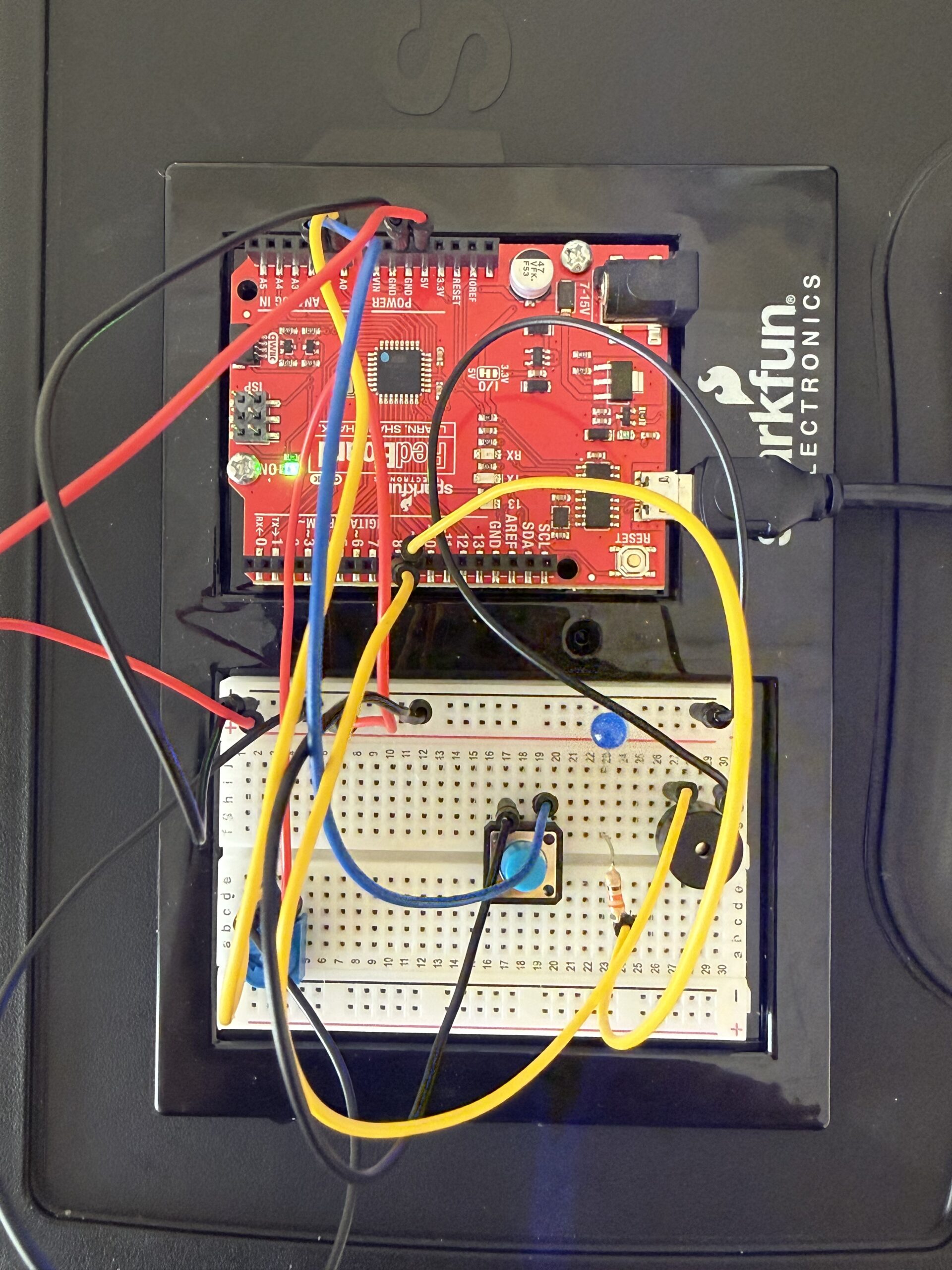
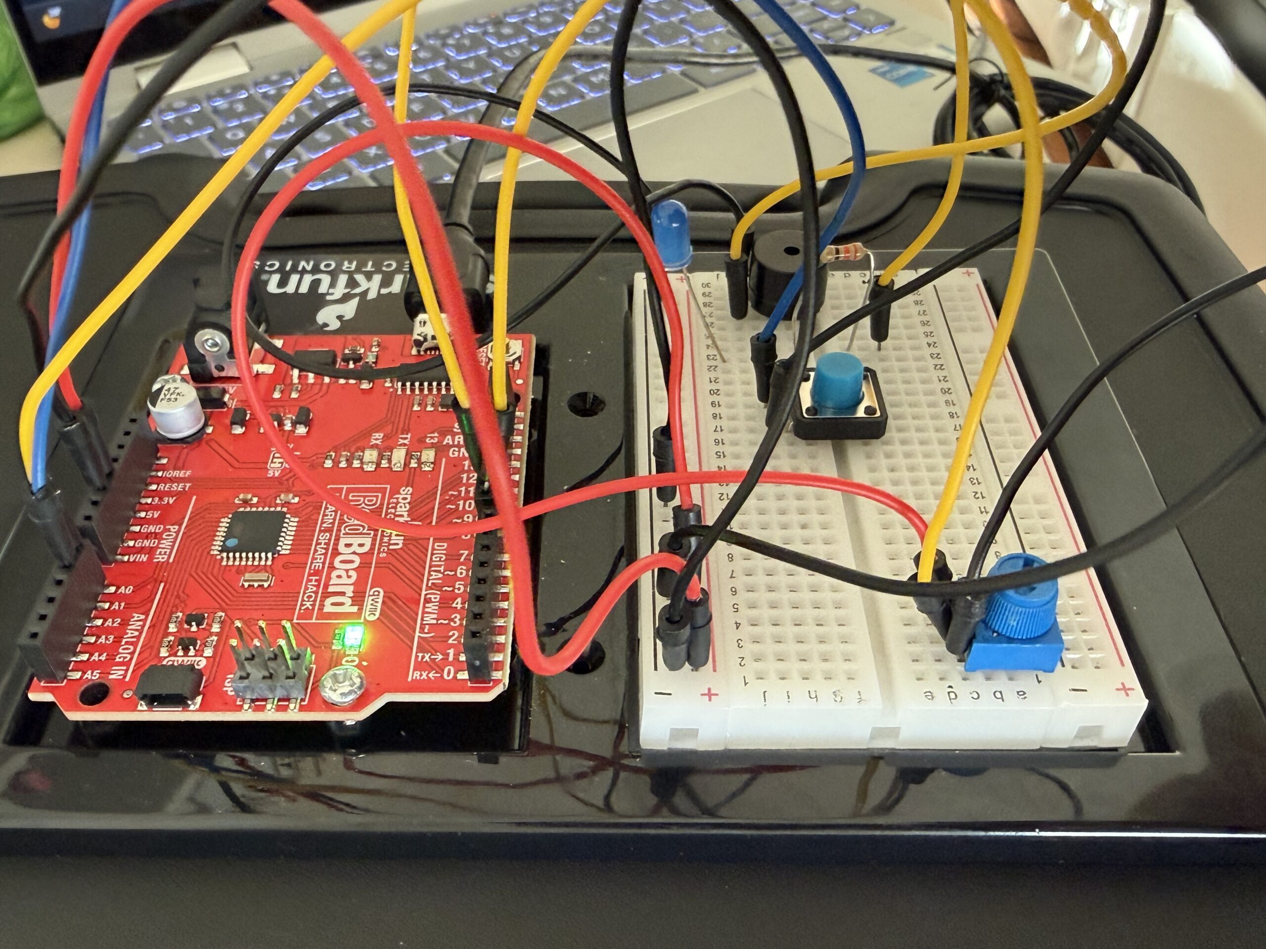
Here are pics and videos:


Video link if not working:

https://drive.google.com/file/d/1pQPYnyUyf5OOBwbfCVHiDrsOvqDn_P3d/view?usp=sharing

Here is my GitHub link:
https://github.com/farahshaer/Intro-to-IM/blob/4ff1ee52b33d4edf72a1f905fc3d014cd8dfadb6/sketch_apr14a.ino 

Overall concept

So for this project, I built an interactive music system that plays two different songs (Jennifer’s Body by Ken Carson and Die with a Smile by Bruno Mars), and you can control the pitch of the melodies. I included a buzzer for the sound output, a button to switch between the songs, a potentiometer to change the pitch, and an LED that visually blinks along with the music. The main idea was to create something interactive where you can actually affect the sound while it is playing.

Code Highlight

One part of my code that I am particularly proud of is the if statements that switch between the two melodies and make the LED blink:

//mode 0 (melody 1)
  if (mode == 0) {

    int size1 = 15;                                      //number of notes in melody 1
    int noteDuration = 1000 / noteDurations1[thisNote];  //converts note type into time in milliseconds
    int finalPitch = melody1[thisNote] + pitch;          //combines the meoldy note and the knob turning (can adjust the note using the potentiometer)
    tone(buzzer, finalPitch, noteDuration);              //plays sound on buzzer
    digitalWrite(led, HIGH);                             //turns led on while the note is playing
    delay(noteDuration);                                 //waits for note to finish
    digitalWrite(led, LOW);                              //turns the led off between the notes and for blinking effect
    delay(noteDuration * 0.3);                           //short pause between the notes to make the melody clearer
    noTone(buzzer);                                      //stops sound before next note
    thisNote++;                                          //moves to next note in the melody
    if (thisNote >= size1) thisNote = 0;                 //if at the end of the melody go back to the start (loop song)
  }


  if (mode == 1) {
    int size2 = 23;                                      //number of notes in melody 2
    int noteDuration = 1000 / noteDurations2[thisNote];  //converts note into time (mill sec)
    int finalPitch = melody2[thisNote] + pitch;          //applys the pitch shift from the potentmeter
    tone(buzzer, finalPitch, noteDuration);              //plays sound
    digitalWrite(led, HIGH);                             //turns led on during the sound
    delay(noteDuration);                                 //wait for note
    digitalWrite(led, LOW);                              //led off
    delay(noteDuration * 0.3);                           //pause between notes
    noTone(buzzer);                                      //stops sound

    thisNote++;                           //go to the next note when done
    if (thisNote >= size2) thisNote = 0;  //loop back to start when song ends
  }
}

This is the core of my project because instead of playing an entire song at once, it processes one note at a time, which allows for real-time interaction through the button and the potentiometer. The code selects the current note, modifies pitch with the sensor input, and then outputs the sound plus the LED, while moving to the next state.

Reflection/future work

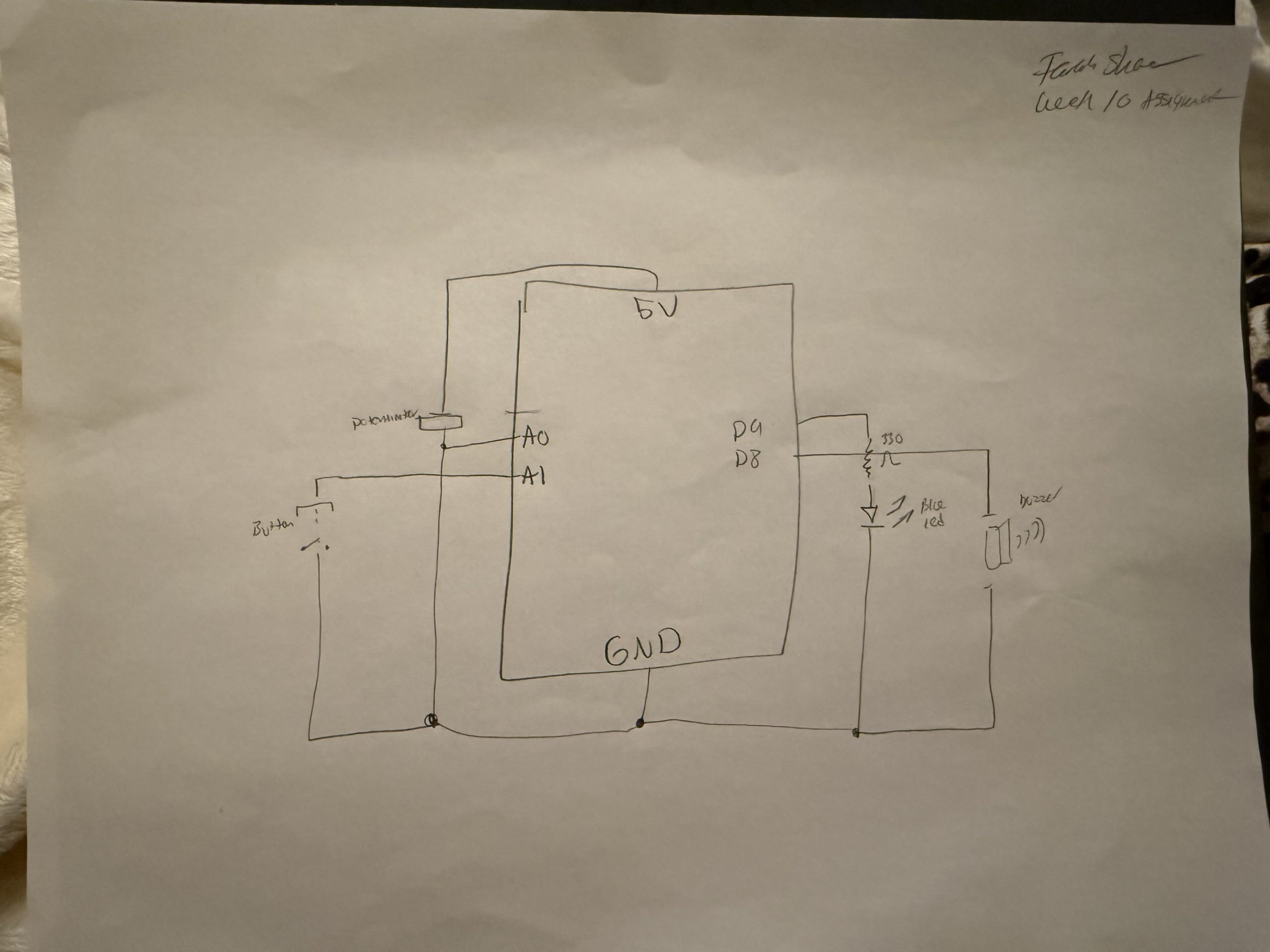
I cannot lie, I had trouble with the code, but the wiring was straightforward once I understood how each component connected to the Arduino. The buzzer is connected to digital pin 8, and outputs sound using the tone() function. The LED is connected to digital pin 9 with a resistor, and it provides visual feedback by blinking in sync with each note. The button is connected using INPUT_PULLUP, meaning it reads HIGH when not pressed and LOW when pressed, which required me to wire one side to ground so the logic would work correctly. The potentiometer is connected to analog pin A0, with one side connected to 5V, the other to ground, and the middle pin sending a variable signal that controls pitch in the code.

For the code, I used a variable called thisNote, which stores the current position in the melody array. Instead of using a for loop to play the entire song at once, the code plays one note per loop cycle, which allows for constant checking for input changes while the music is playing. At first, I used for loops, and it just was not working. The Arduino got stuck inside the loop, the button presses were ignored until the song finished, and the potentiometer did not update in real time, so switching to thisNote, it made the program run one note at a time inside the loop. So the Arduino can check the button constantly, and the song can change and pitch in real time.

I also had a problem with the button logic, because at first I wrote if (buttonState == LOW) and it caused it to continuously trigger while the button was held down, which made the song behave unpredictably. So I used chatgpt to debug and I learned to use lastButtonState with buttonState so the code only detects a transition from high to low (single press instead of holding), and because I used input_pullup, I also had to adjust my thinking since high is not pressed and low was pressed so it was confusing at first because it is the opposite of what I expected.

Overall, I learned that structure matters just as much as logic, especially when dealing with real-time input and output, because small details like button states and loop structure completely change how responsive the system feels. For future improvements, I would add more songs or more modes, and more LEDs or patterns to visualize the rhythm more creatively, and probably replace delay with millis for smoother control.

Here is my schematic:


References:

(I mainly used the lecture slides), but I also used these websites for a better understanding.
https://github.com/hibit-dev/buzzer/blob/e1442497e7c56cee0d5efe73304bdb922b3ab907/src/songs/ken_carson_jennifers_body/ken_carson_jennifers_body.ino

https://github.com/hibit-dev/buzzer/blob/e1442497e7c56cee0d5efe73304bdb922b3ab907/src/songs/die_with_a_smile/die_with_a_smile.ino

https://docs.arduino.cc/built-in-examples/digital/toneMelody/

https://docs.arduino.cc/built-in-examples/digital/InputPullupSerial/