Exercise 1
Arduino GitHub File:
https://github.com/MouzaAlMheiri/Intro-to-IM/blob/main/week11-exercise1
Arduino Set-up:
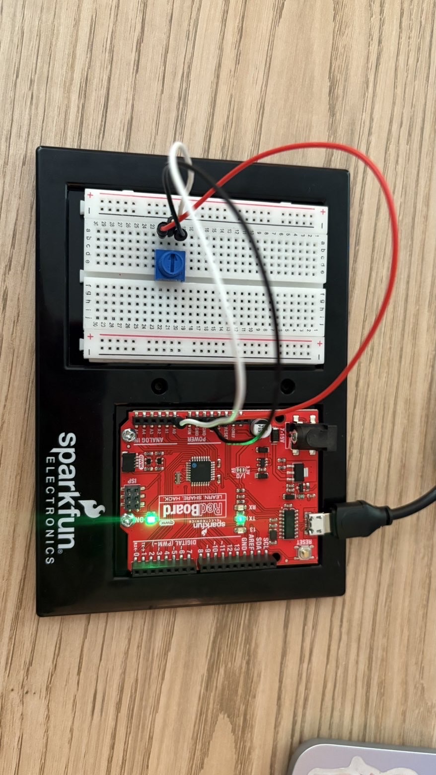
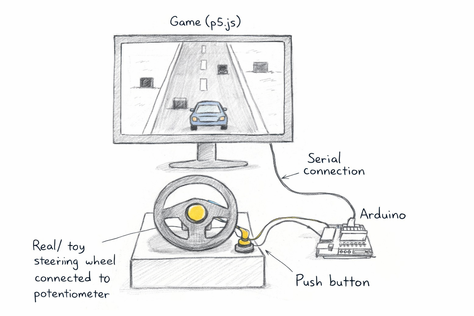
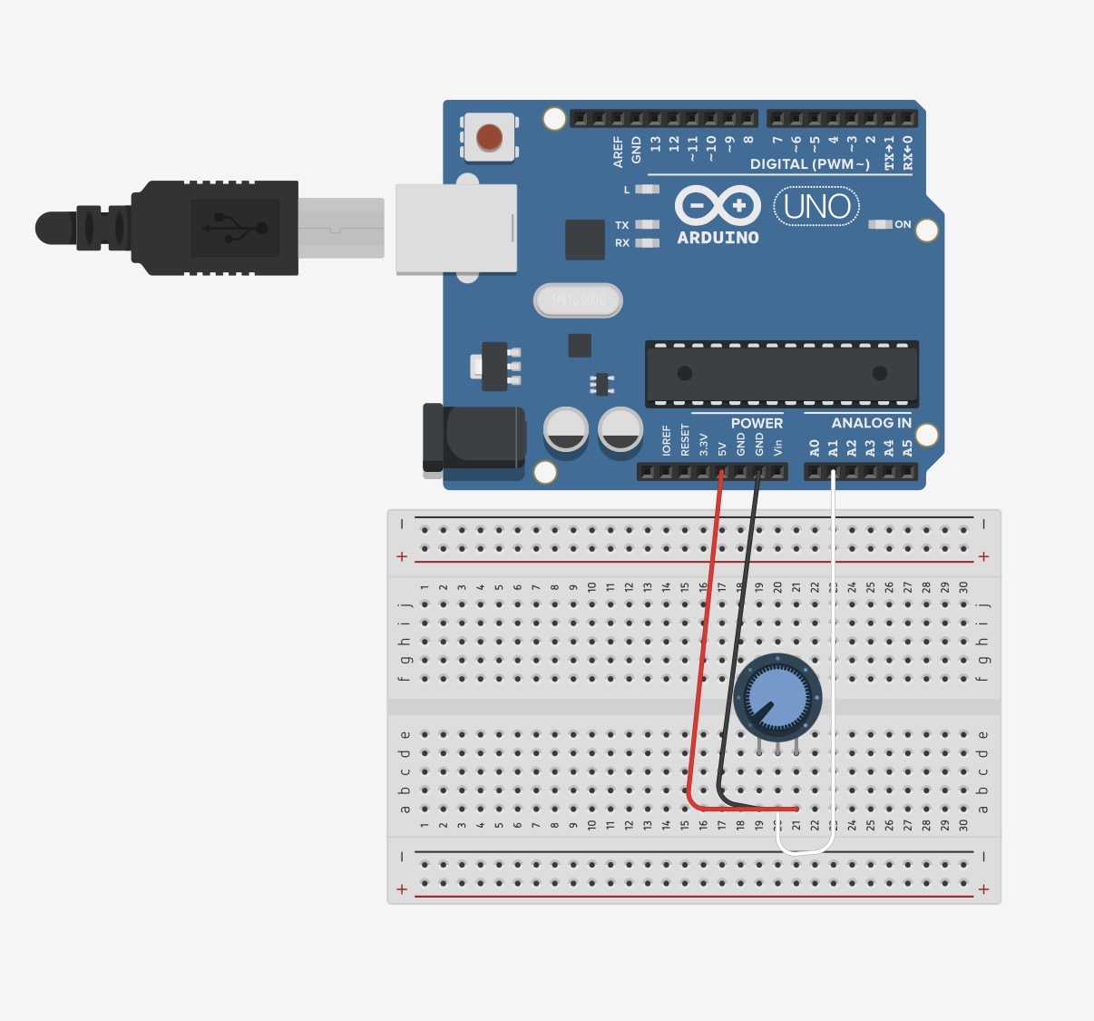
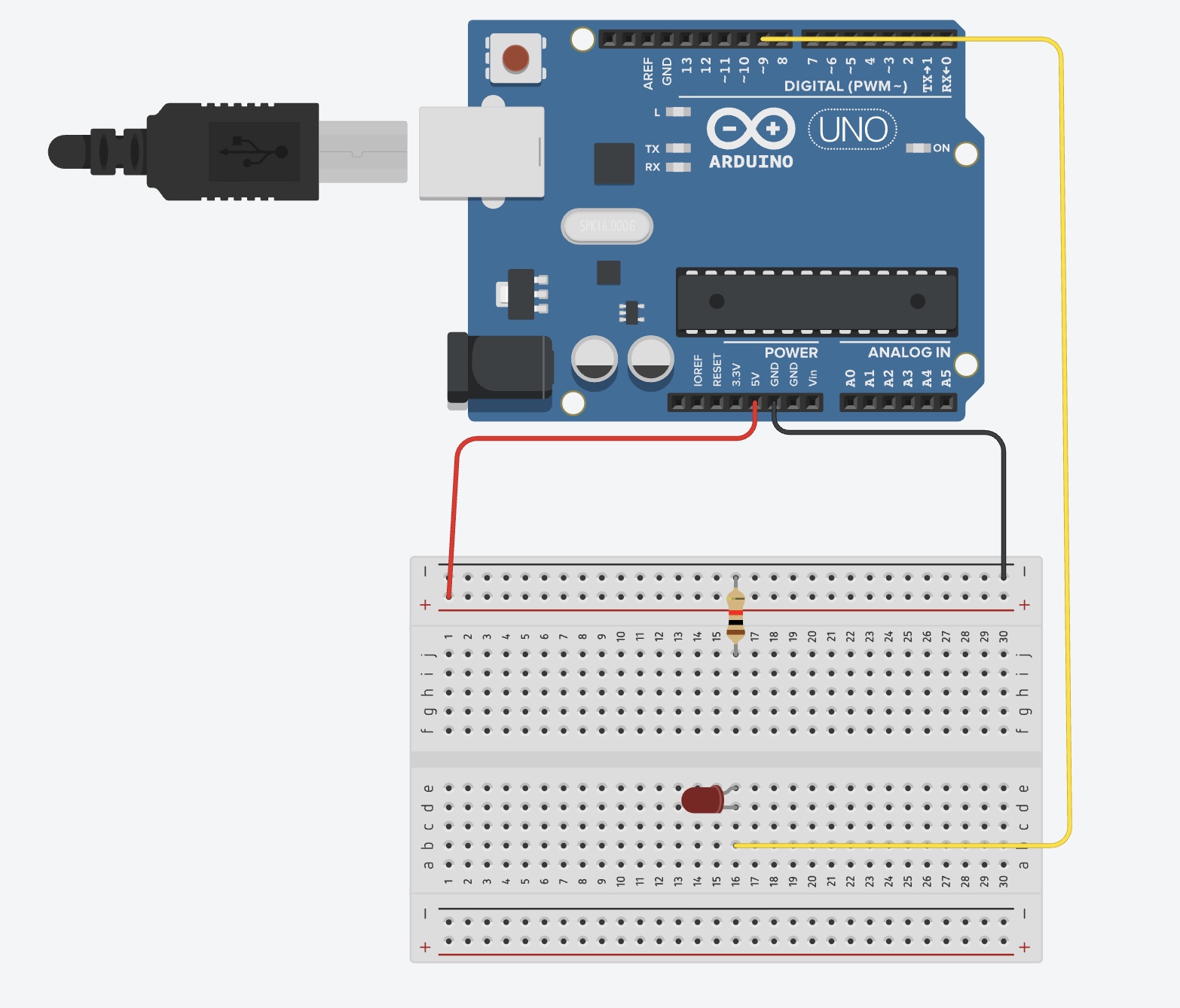
Arduino Illustration:
Project Demo:
Exercise 2
Arduino GitHub File:
https://github.com/MouzaAlMheiri/Intro-to-IM/blob/main/week11-exercise2
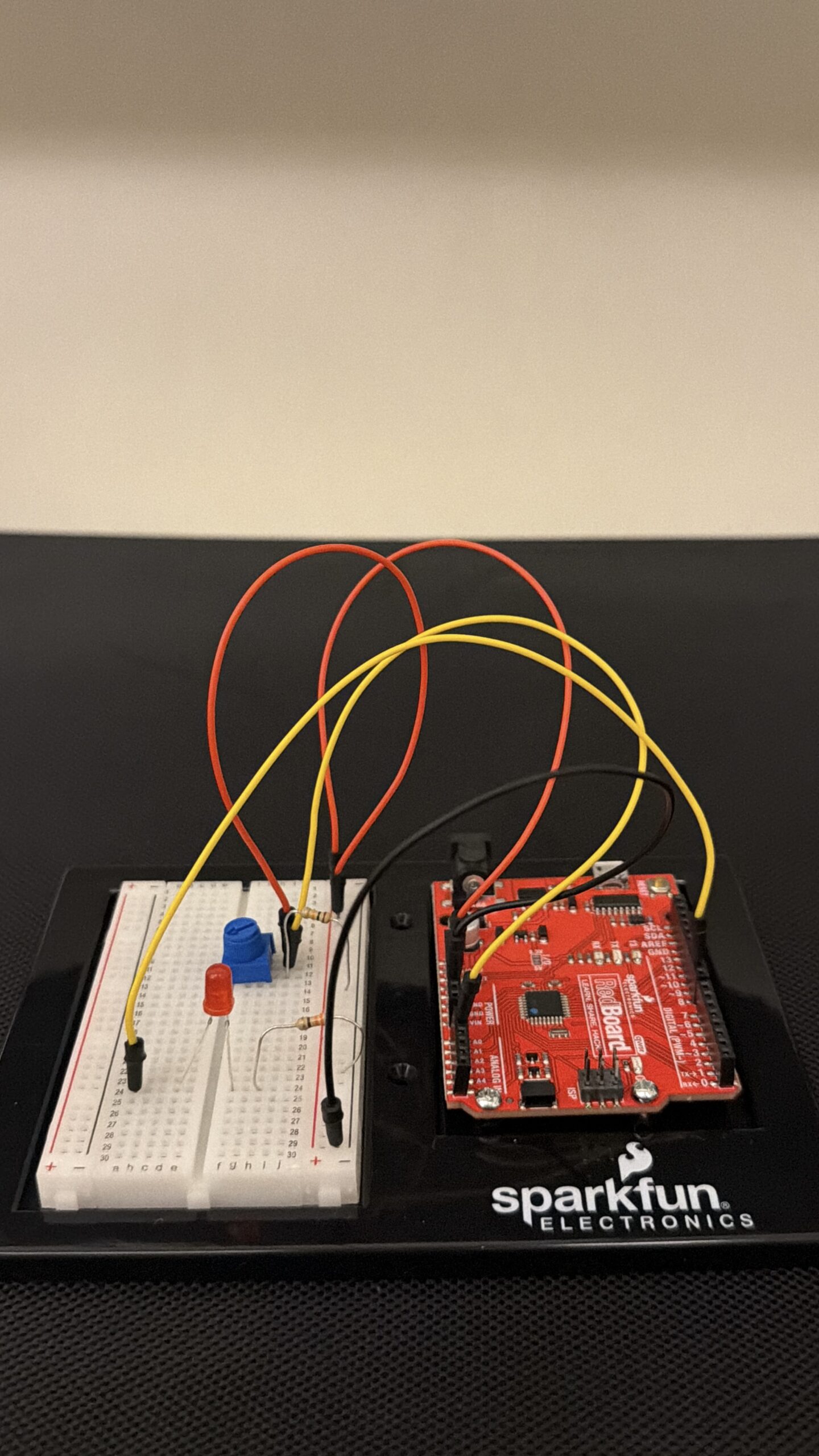
Arduino Set-up:
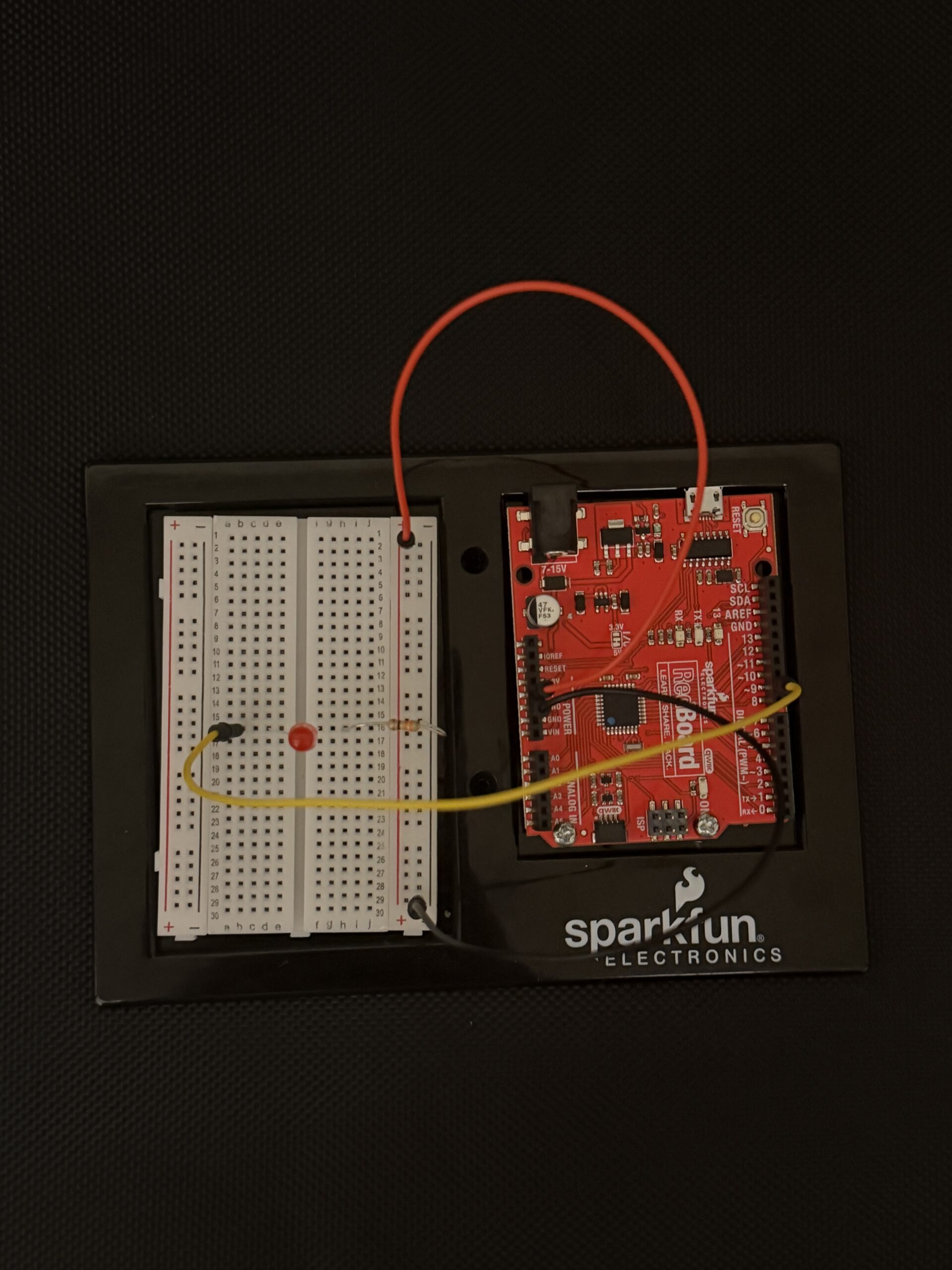
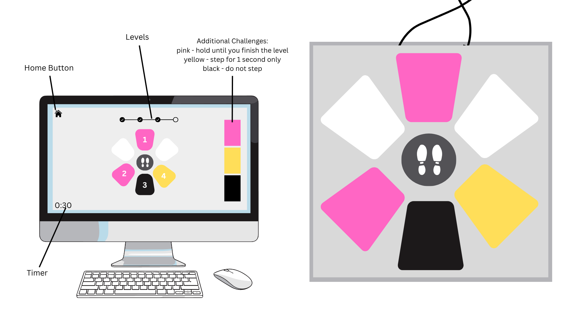
Arduino Illustration:
Project Demo:
Exercise 3
Arduino GitHub File:
https://github.com/MouzaAlMheiri/Intro-to-IM/blob/main/week11-exercise2
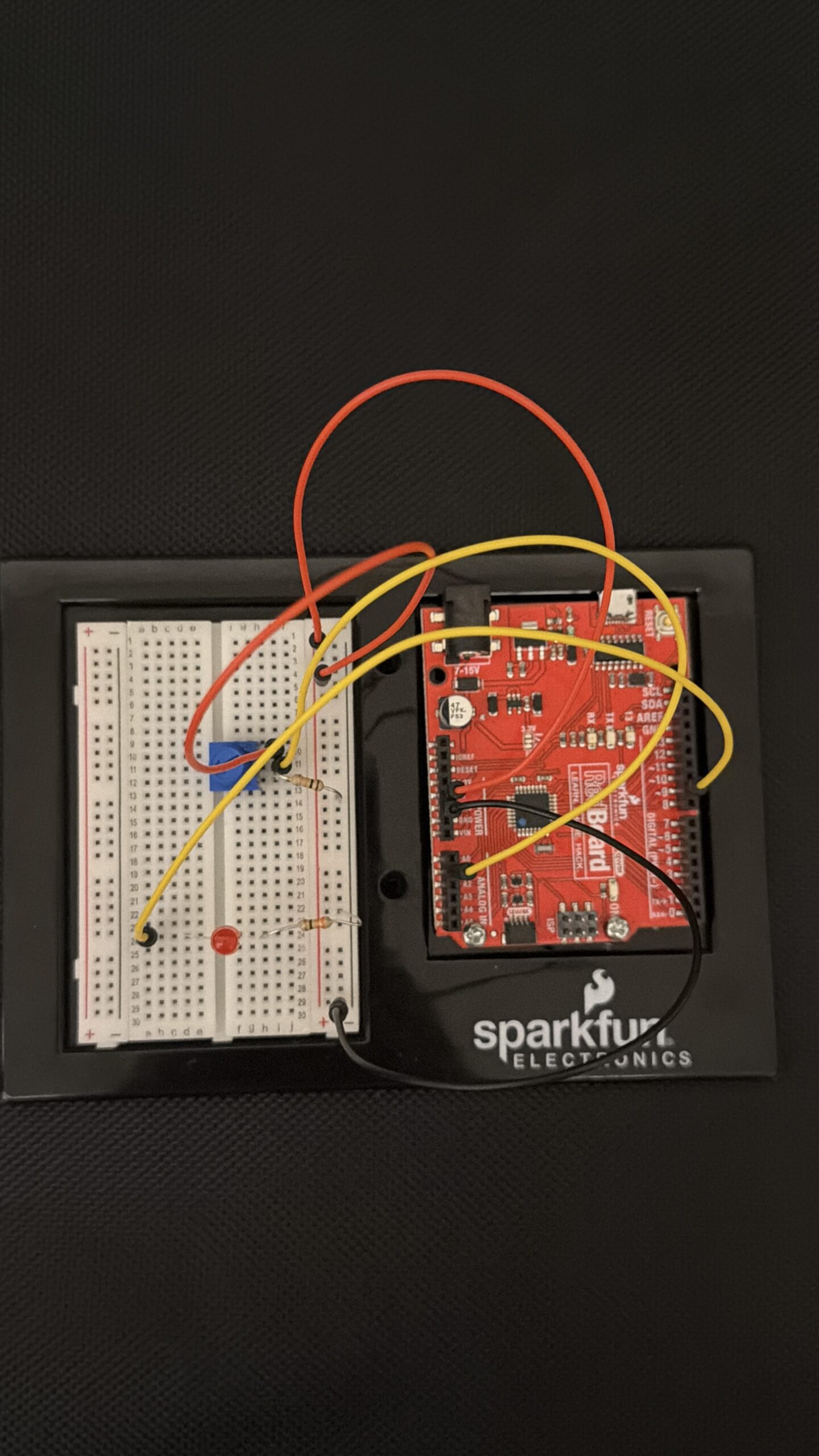
Arduino Set-up:
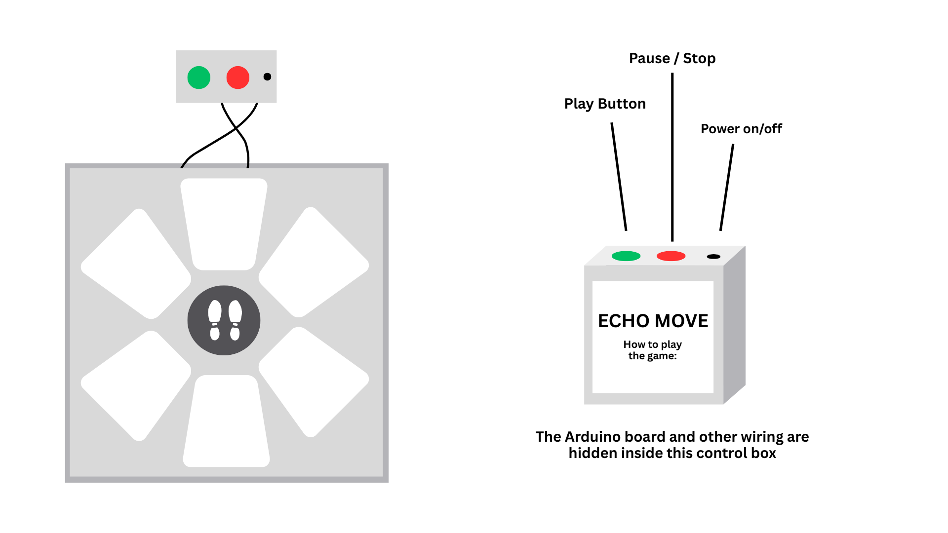
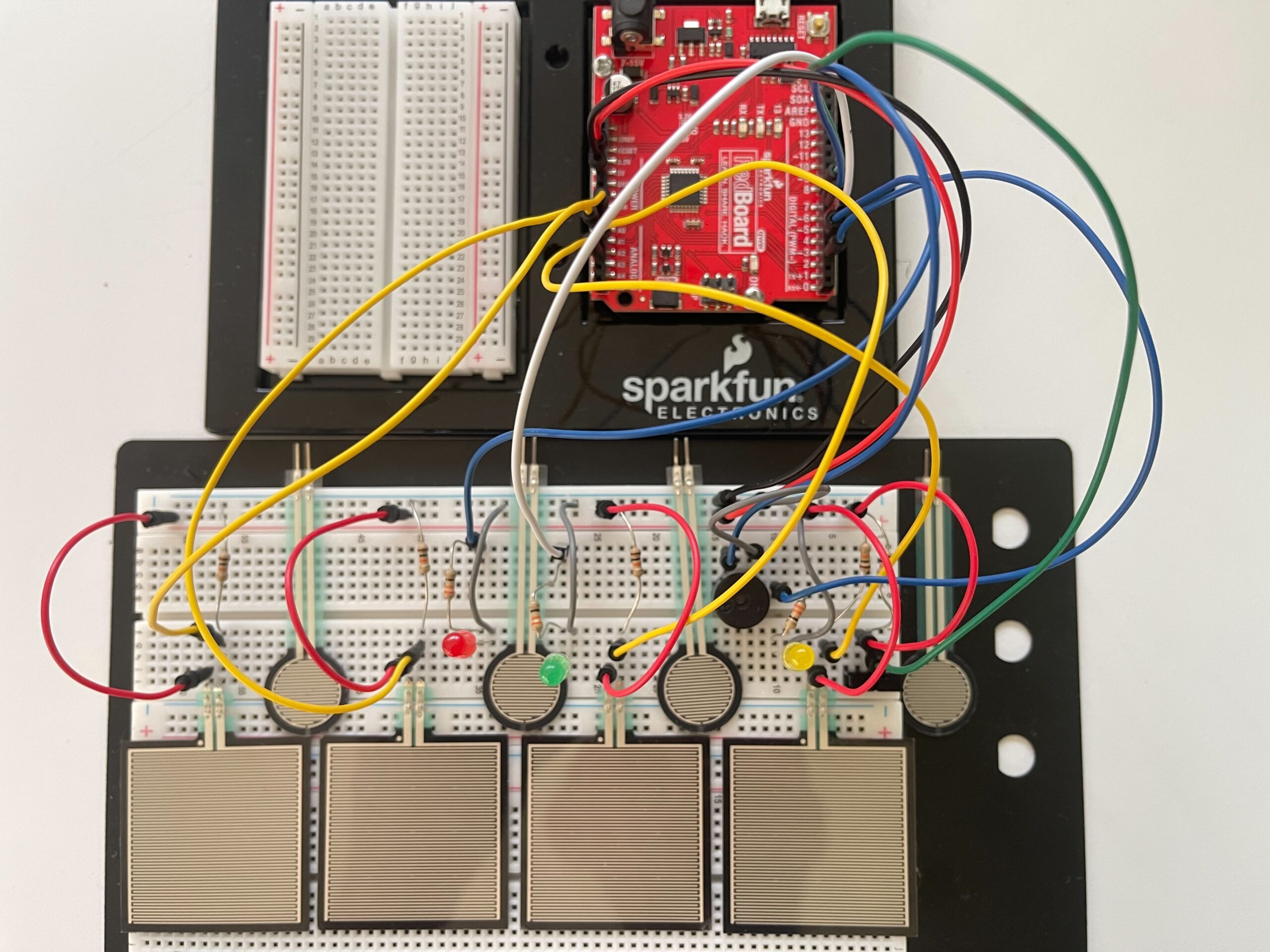
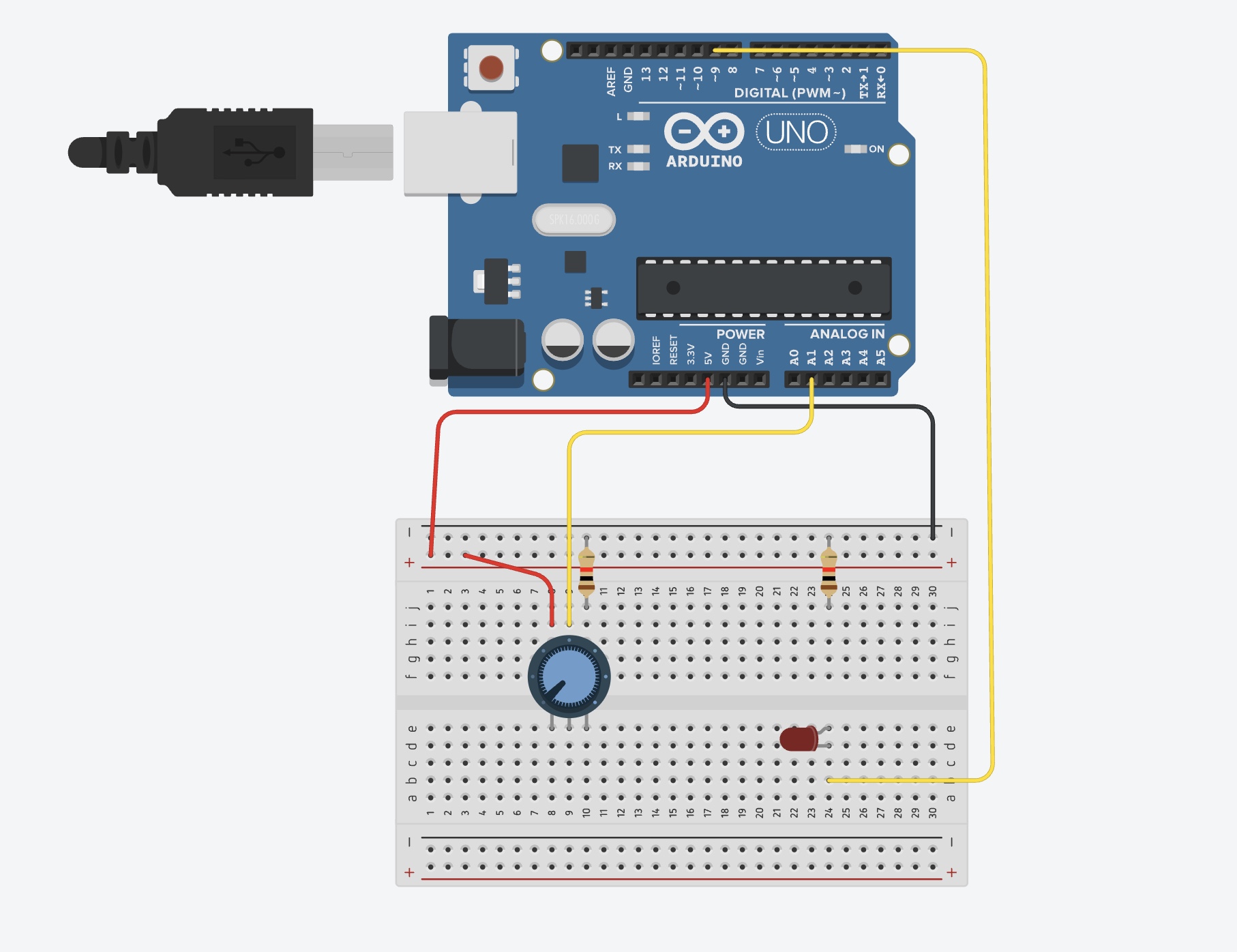
Arduino Illustration:
Project Demo:
Concept
This week was all about making things communicate. Before this, everything we made stayed inside Arduino. This time, we connected Arduino to p5 so the physical and digital sides could talk to each other.
At first it sounded simple, but it ended up being one of the hardest things we’ve done so far. Not because of the ideas, but because getting everything to connect properly took a lot of trial and error.
Exercises
Across the three exercises, we explored different ways of communication.
In the first exercise, we sent data from Arduino to p5. We used the potentiometer to move a circle across the screen. This helped us understand how sensor values can control something visually.
In the second exercise, we reversed the direction. p5 controlled the LED on Arduino. This made us realize that communication goes both ways, and that sending data is just as important as receiving it.
In the third exercise, we combined both directions. The potentiometer controlled movement in p5, and when something happened on the screen, it sent a signal back to Arduino to turn on the LED. This was the most interesting part because everything was connected and reacting together.
Code Highlight
One part that really helped us was reading the sensor data correctly in p5
let str = port.readUntil("\n");

if (str.length > 0) {

  str = trim(str);

  let sensorValue = int(str);

  if (!isNaN(sensorValue)) {

    x = map(sensorValue, 0, 255, 0, width);

  }

}
This made sure we only used valid data and mapped it properly to the screen. Once this worked, everything became much smoother.
Problems Encountered
We had a lot of issues this week, mostly with the connection. The serial port wouldn’t open, or p5 wouldn’t receive any values. Sometimes things worked and then suddenly stopped working again.
We realized most of these problems were small things, like forgetting to close the Serial Monitor or not formatting the data correctly.
Reflection
This week helped us understand that interaction is not just about building something, but about connecting things together. Once the connection worked, everything felt more interactive and responsive.
It also made us more patient with debugging. We learned to check things step by step instead of assuming something bigger was wrong.
Collaboration
We worked on this together, which made a big difference. When one of us got stuck, the other could help figure out what went wrong. It also made debugging less frustrating because we weren’t trying to solve everything alone.
Working together helped us understand the system better and move forward faster.
References
p5.js Web Editorhttps://editor.p5js.orgp5 to Arduino
p5.js Web Editorhttps://editor.p5js.orgp5 to Arduino
p5.js and Arduino serial communication – Send a digital sensor to a p5.js sketchYouTube · Scott Fitzgerald28 Mar 2020