EXERCISE 01: ARDUINO TO P5 COMMUNICATION
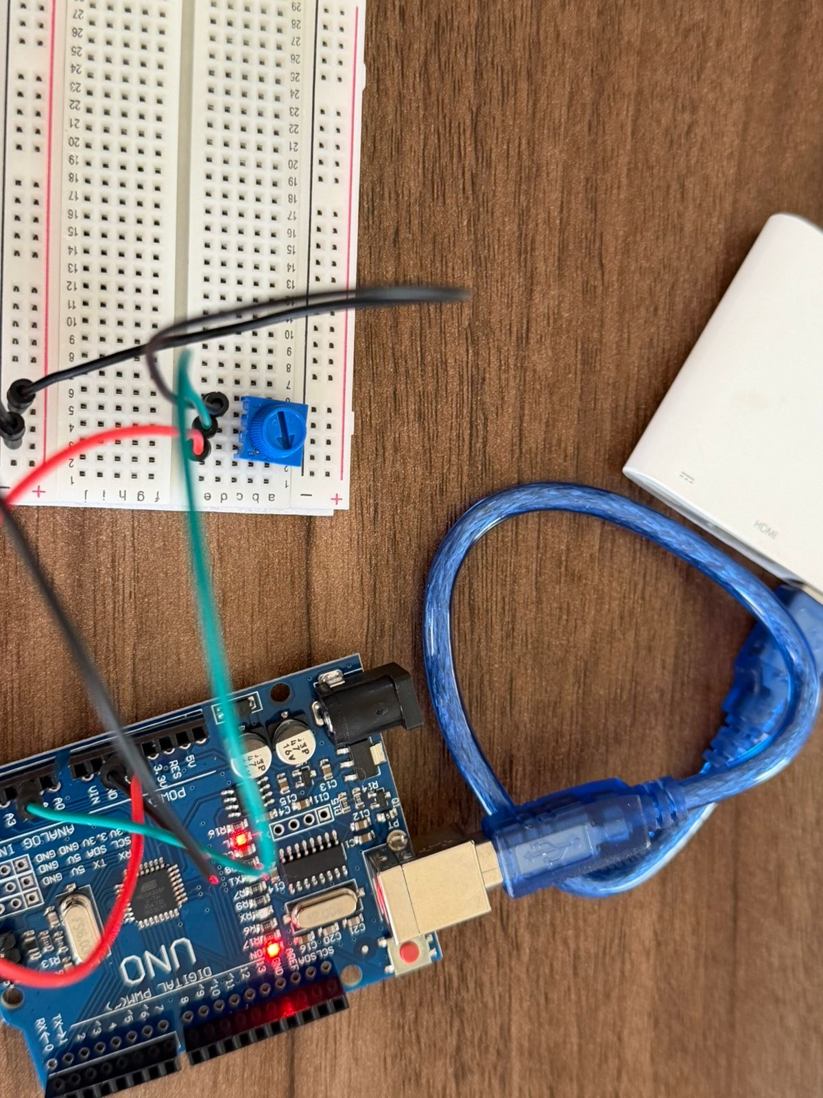
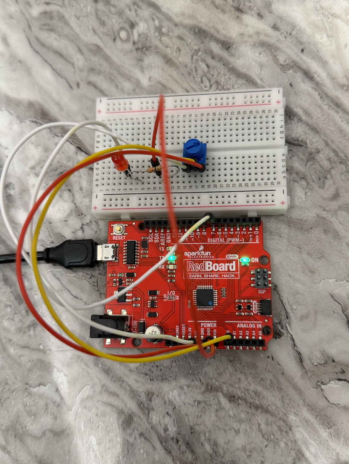
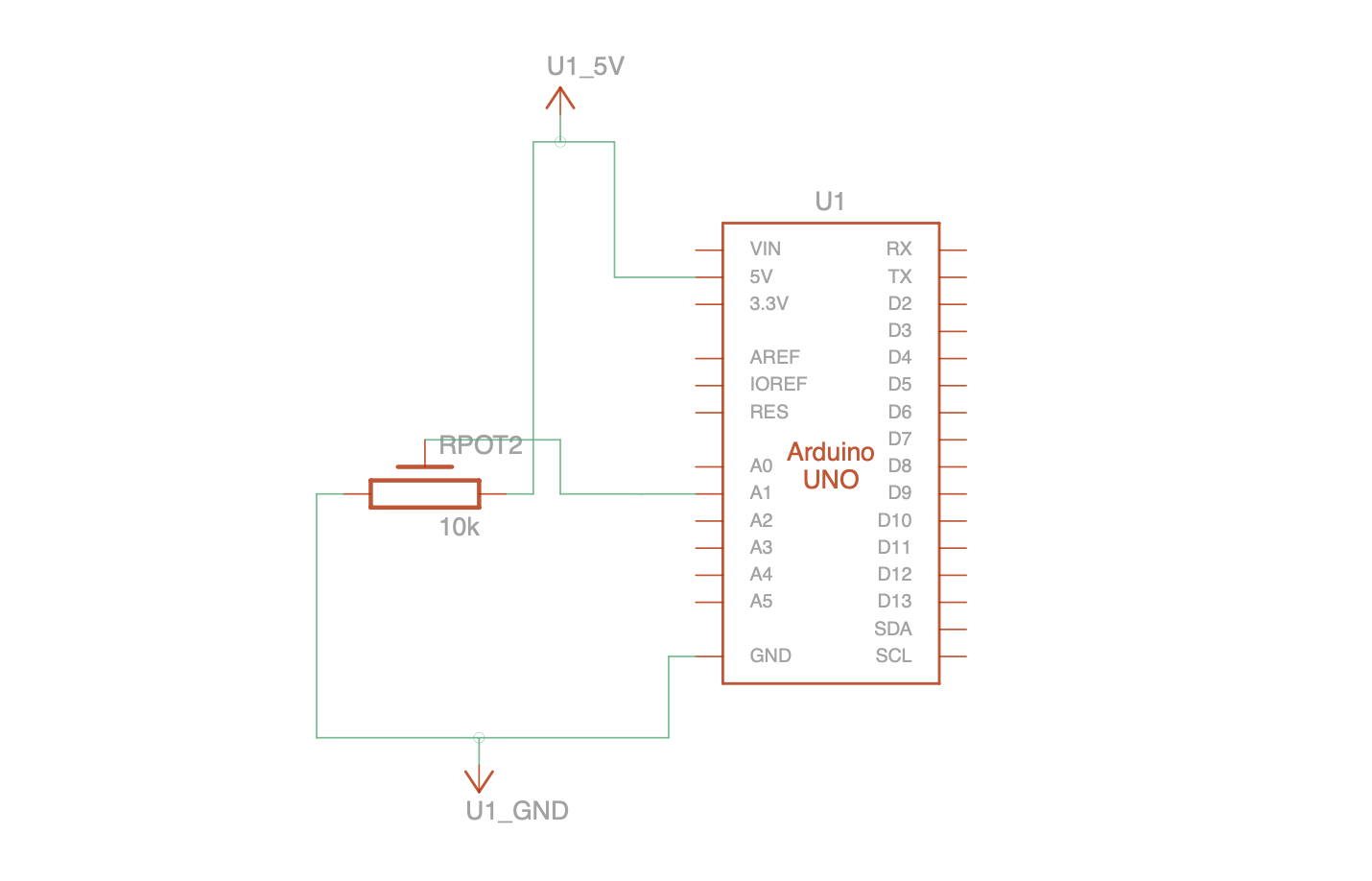
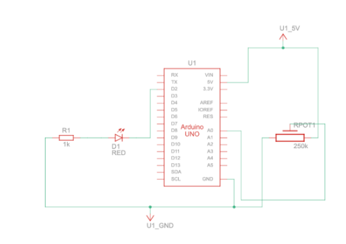
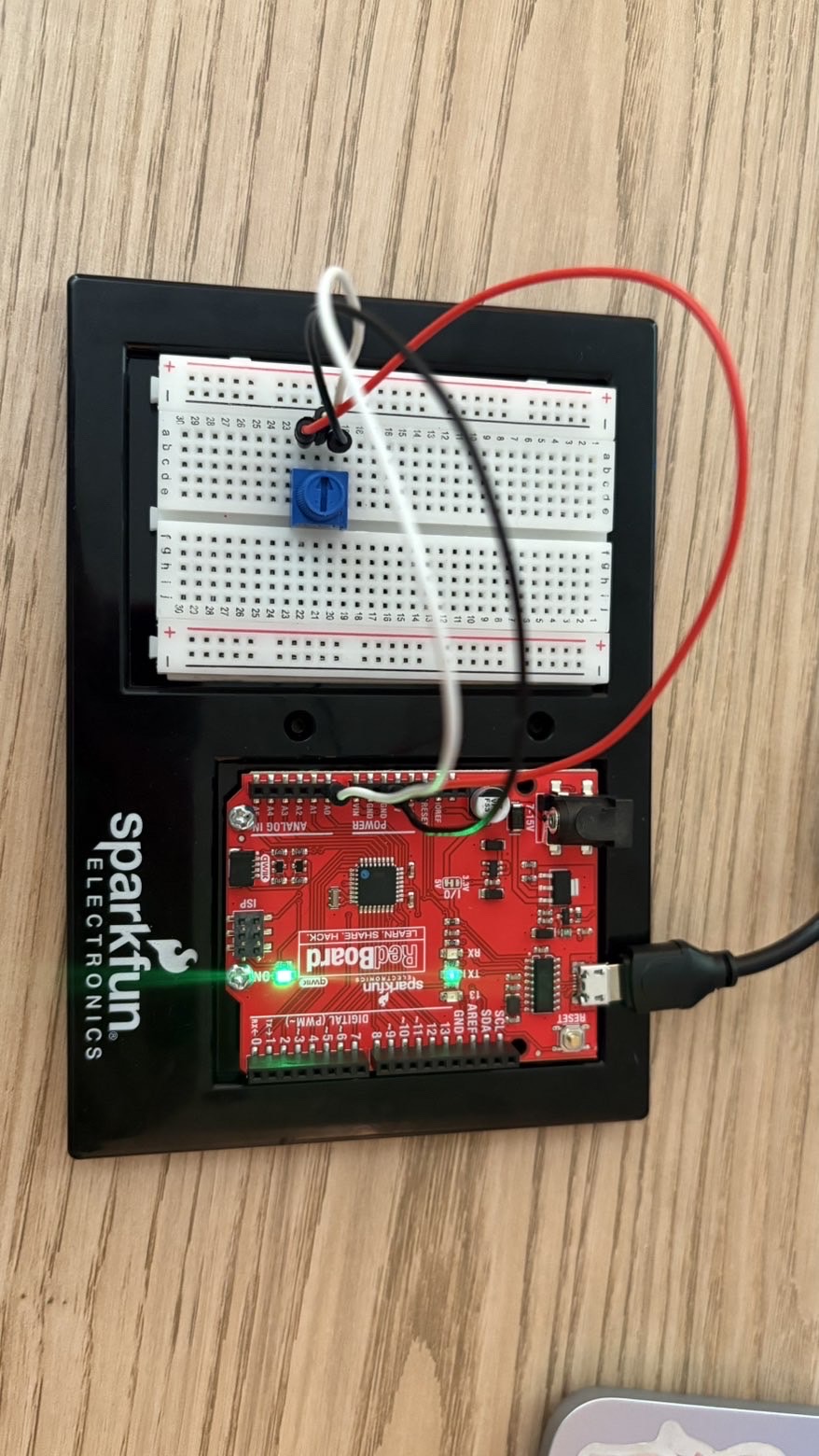
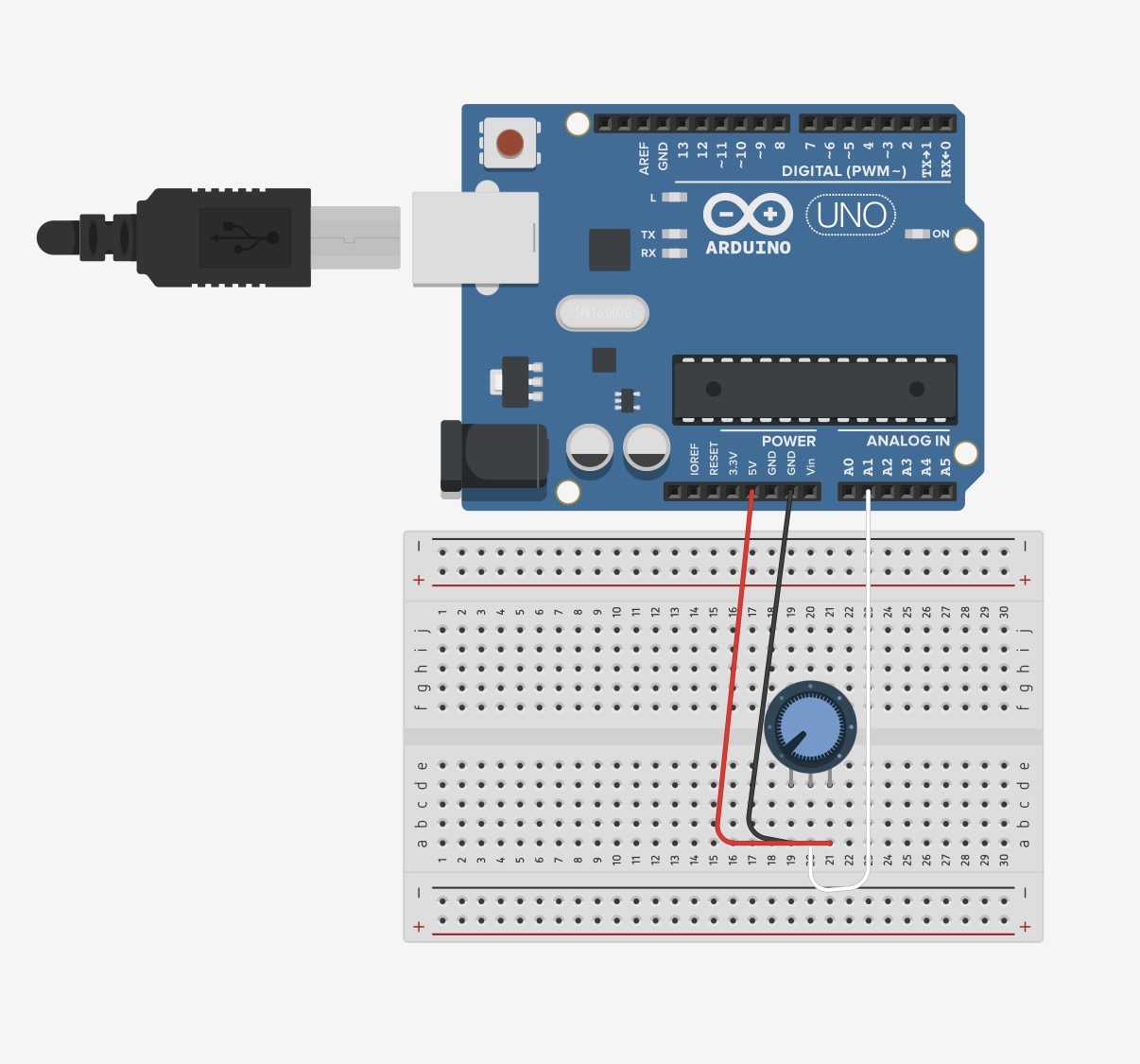
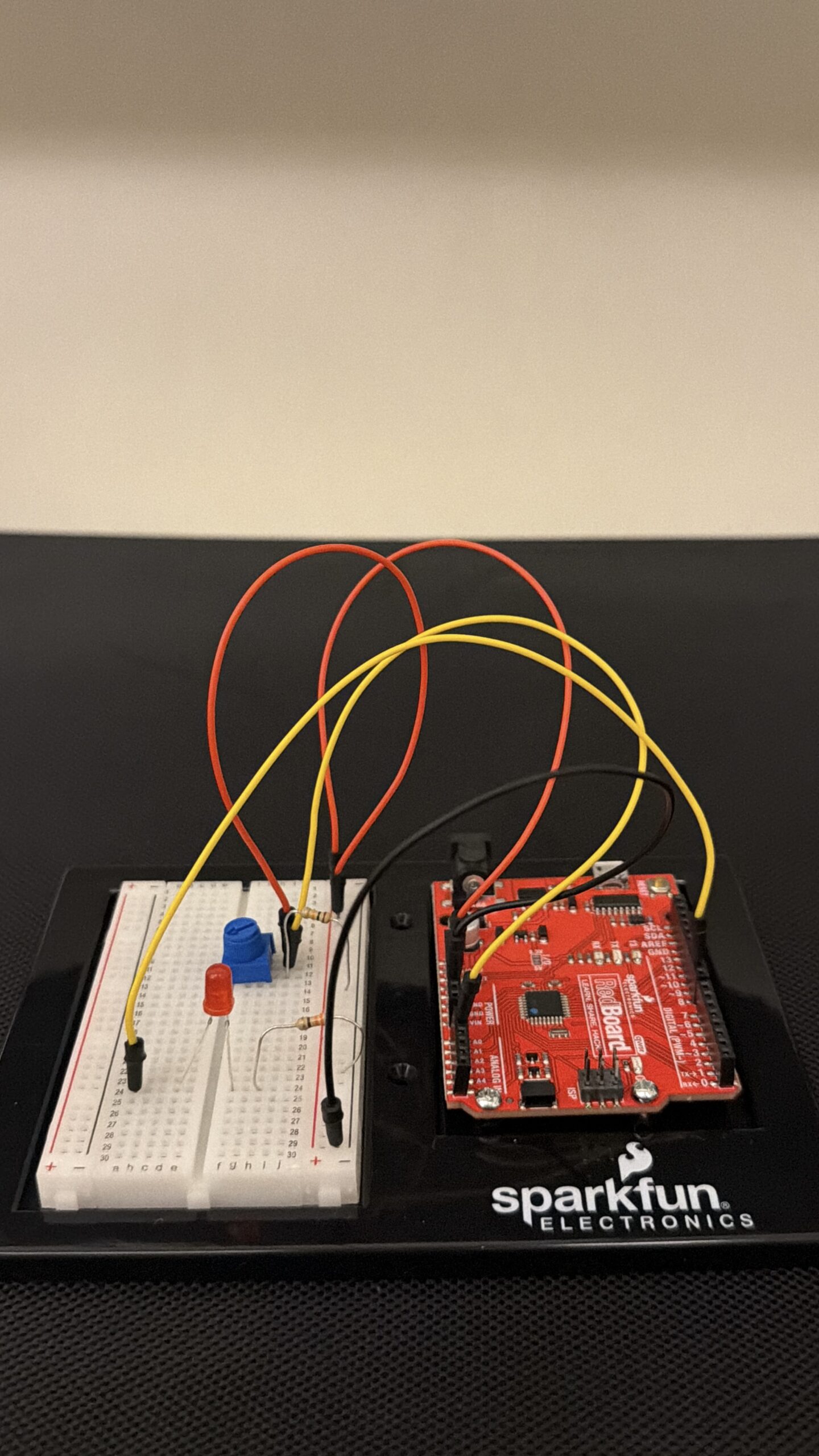
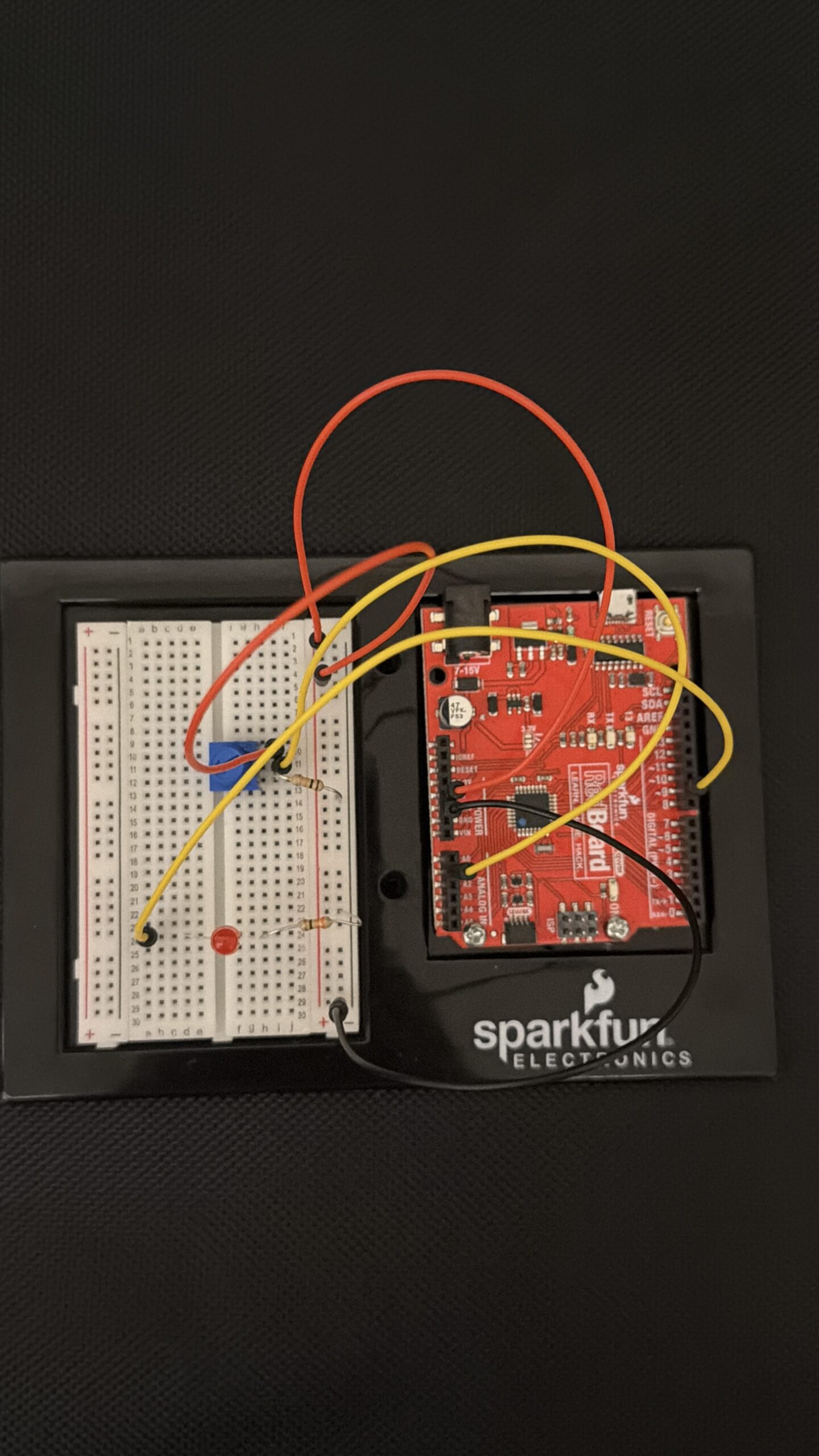
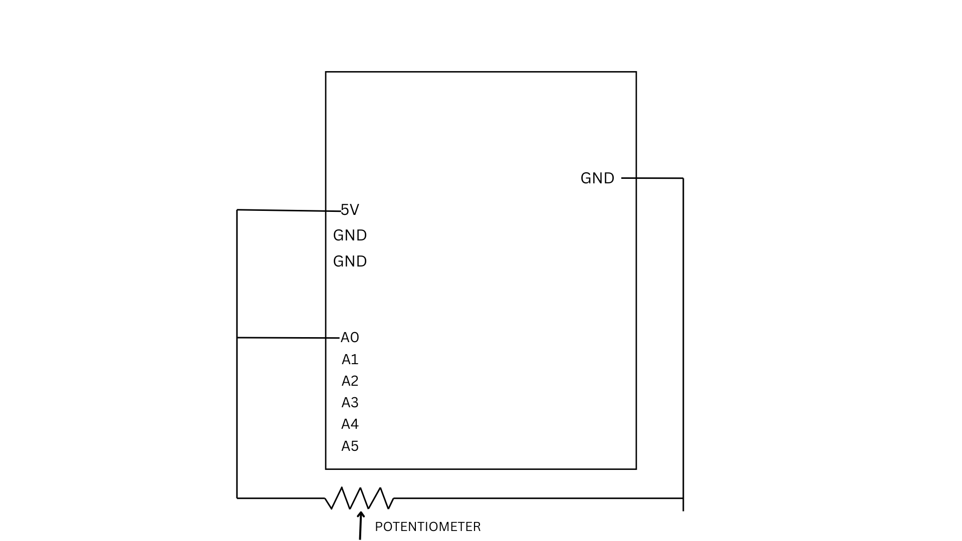
For this exercise, we used a potentiometer as our sensor to control an ellipse in p5.js. As the knob is turned, the Arduino reads the changing analog values and sends them to p5 through serial communication.
let x = map(sensorValue, 0, 255, 50, width - 50);

  ellipse(x, height / 2, 50, 50);
The values are mapped to the x-position of the ellipse, allowing it to move horizontally across the screen while staying centered vertically.
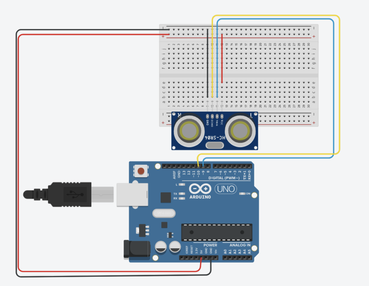
We also did another version of it which basically uses an ultrasonic sensor. The P5 code is same for both, just the mapping is different. You comment out the one user using for a smoother response. The ball movement is corresponding to the the distance detected by the sensor.
Sketch:
EXERCISE 02: P5 TO ARDUINO COMMUNICATION
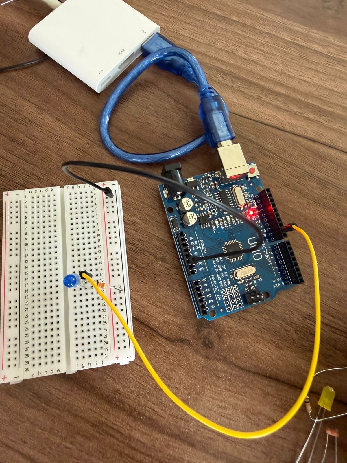
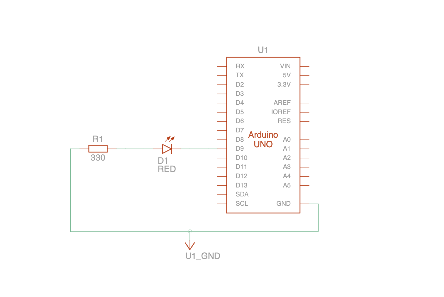
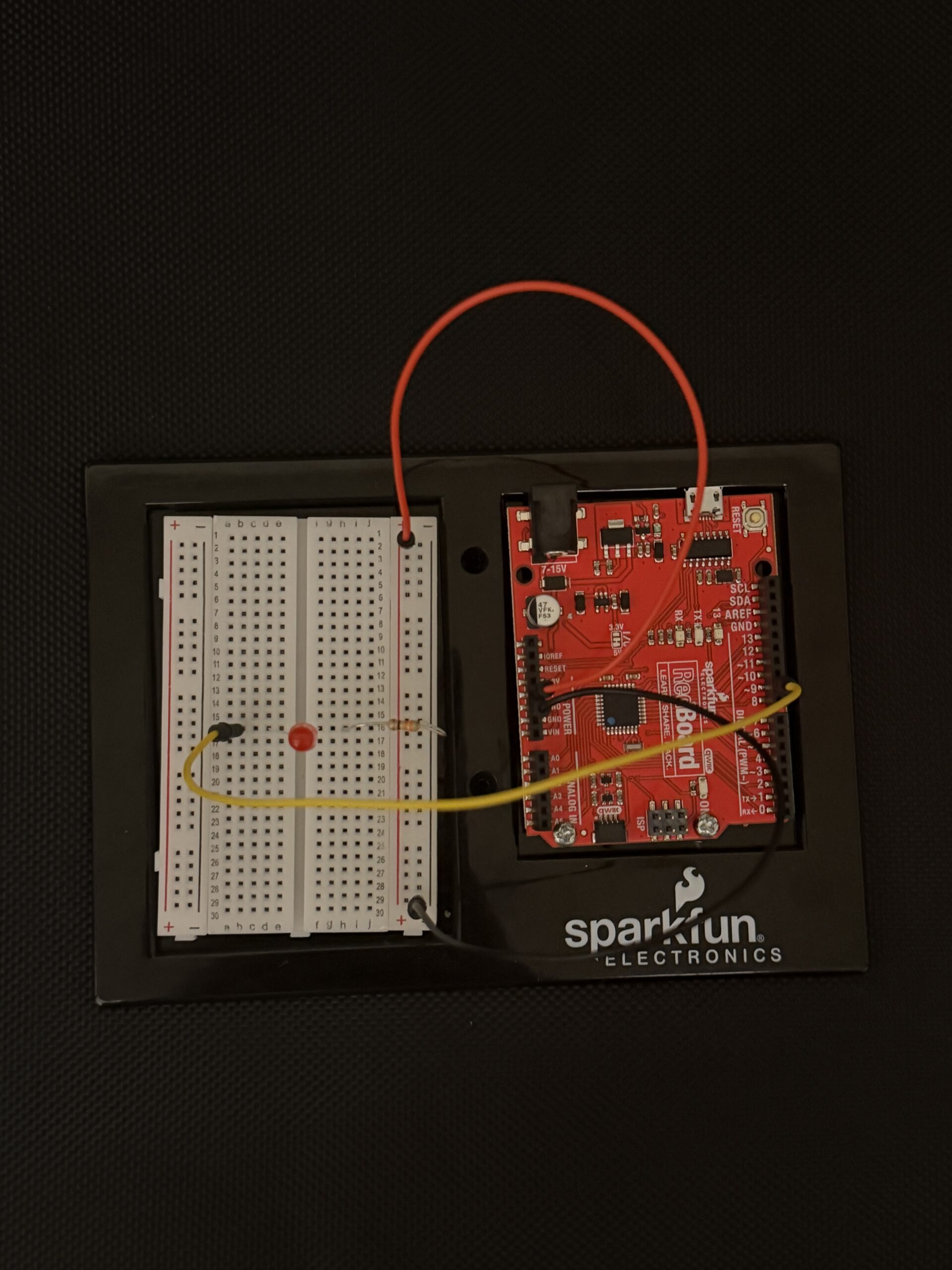
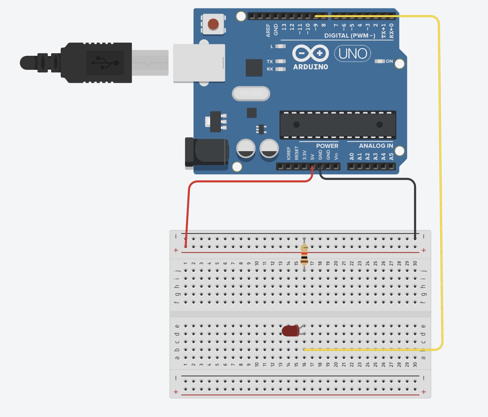
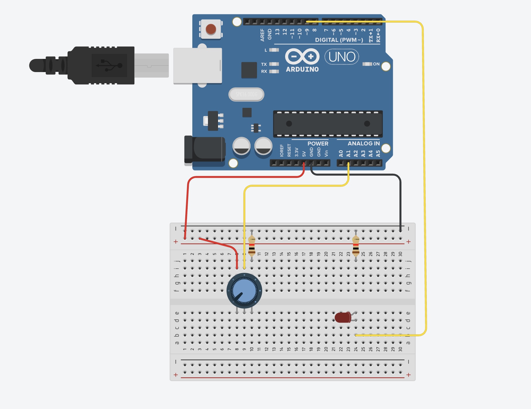
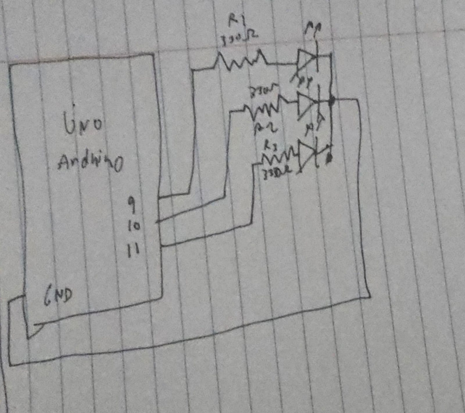
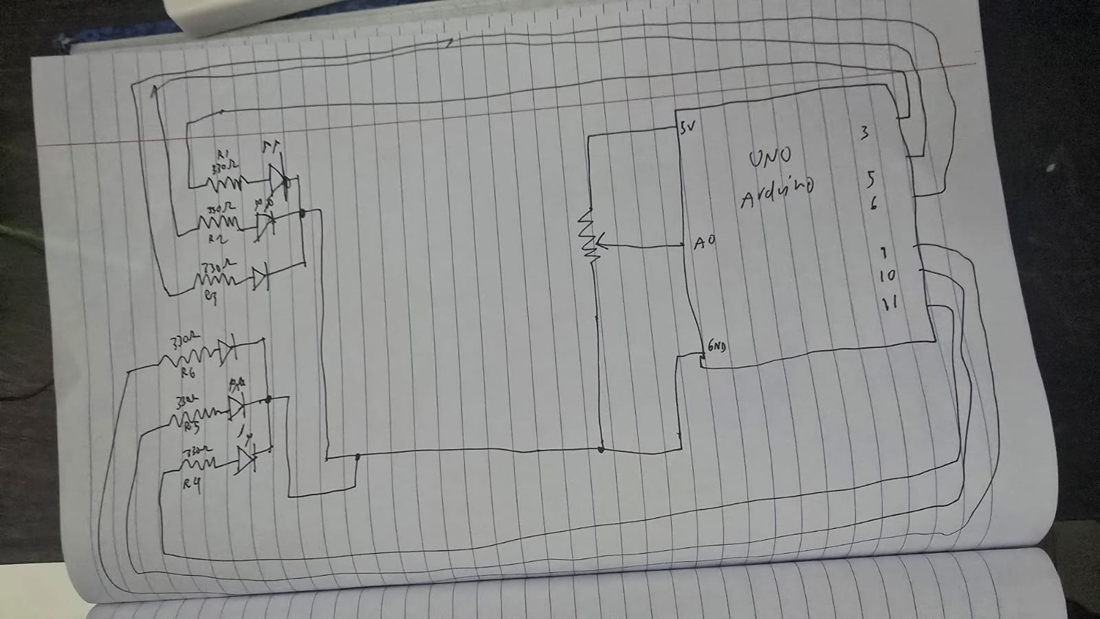
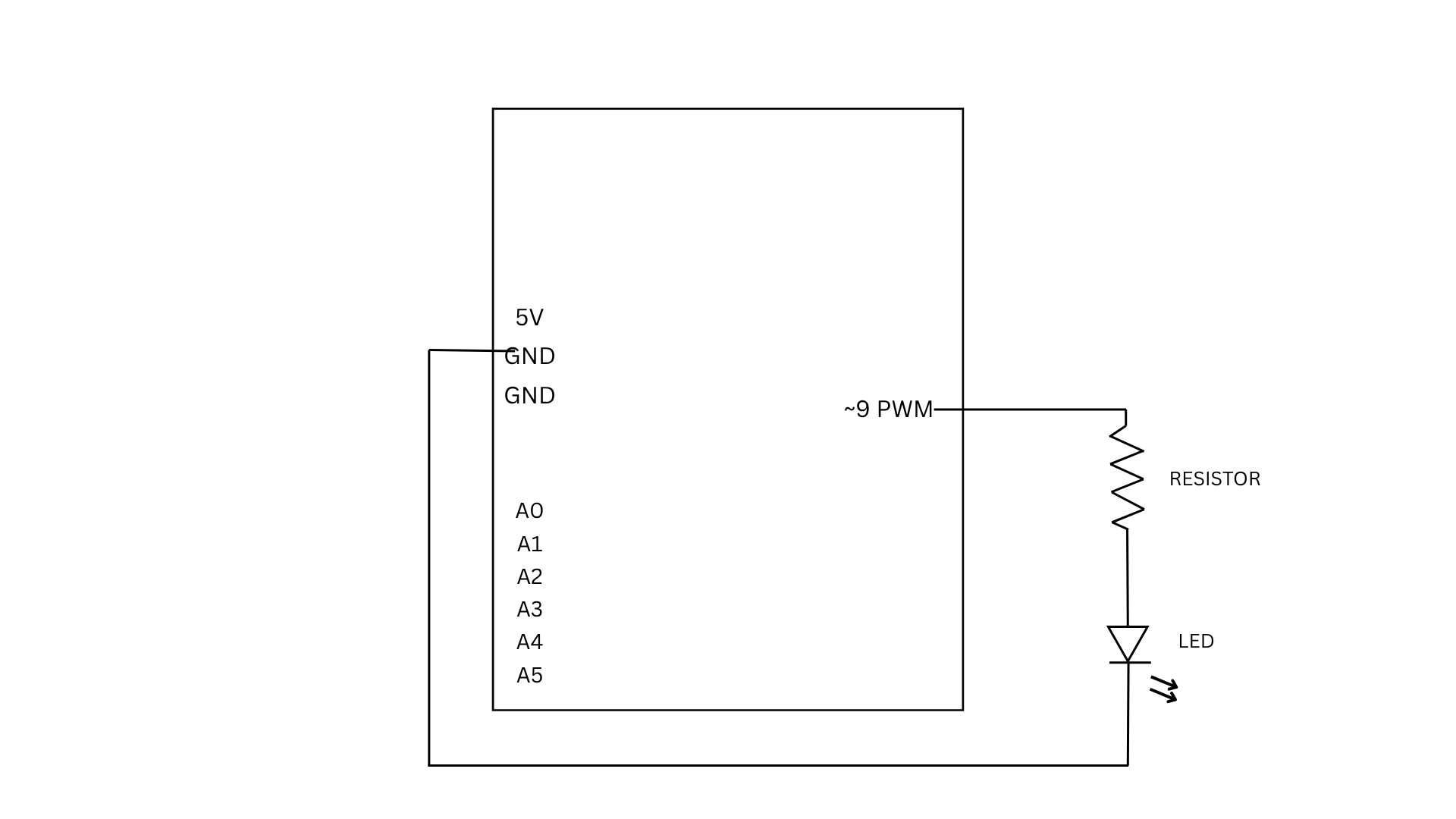
For Exercise 2, we used a slider in p5 to control the brightness of an LED connected to the Arduino. As the slider moves, it sends values from 0 to 255 through serial communication. The Arduino reads these incoming values and uses them to adjust the LED brightness using PWM, making the LED appear dimmer or brighter depending on the slider position.
if (Serial.available() > 0) {

int brightness = Serial.parseInt();

analogWrite(9, brightness);
This part of the code checks if there is incoming data from p5. When a value is received, it reads the number using parseInt() and uses it to control the LED brightness through analogWrite, which determines how bright or dim the LED will be.
EXERCISE 03: BI-DIRECTIONAL COMMUNICATION
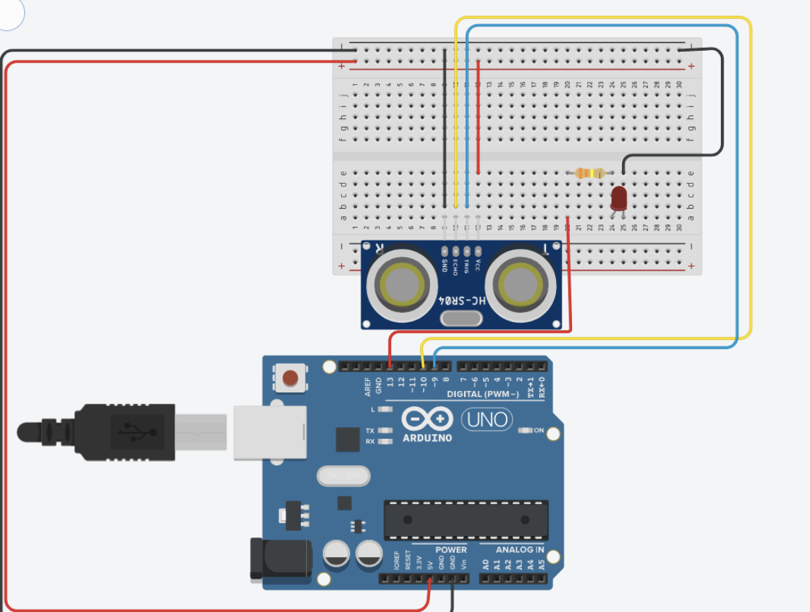
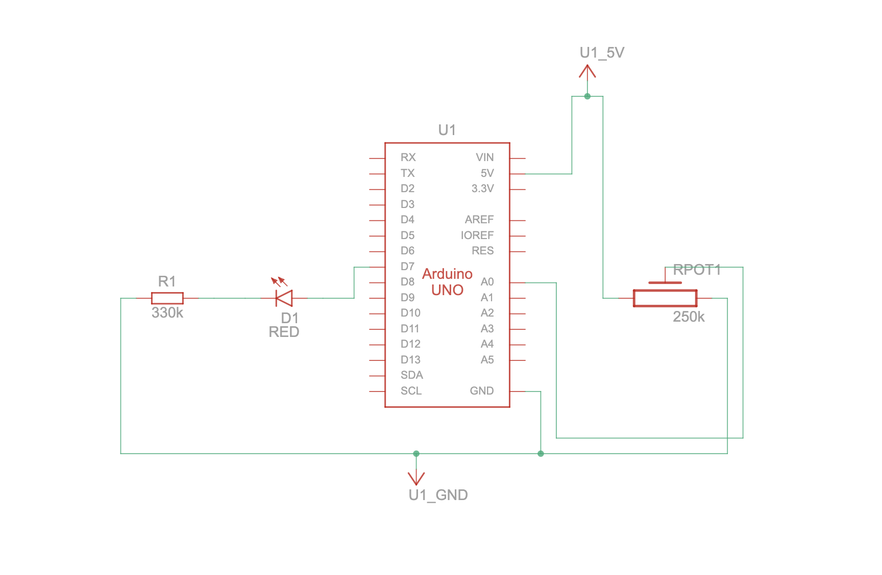
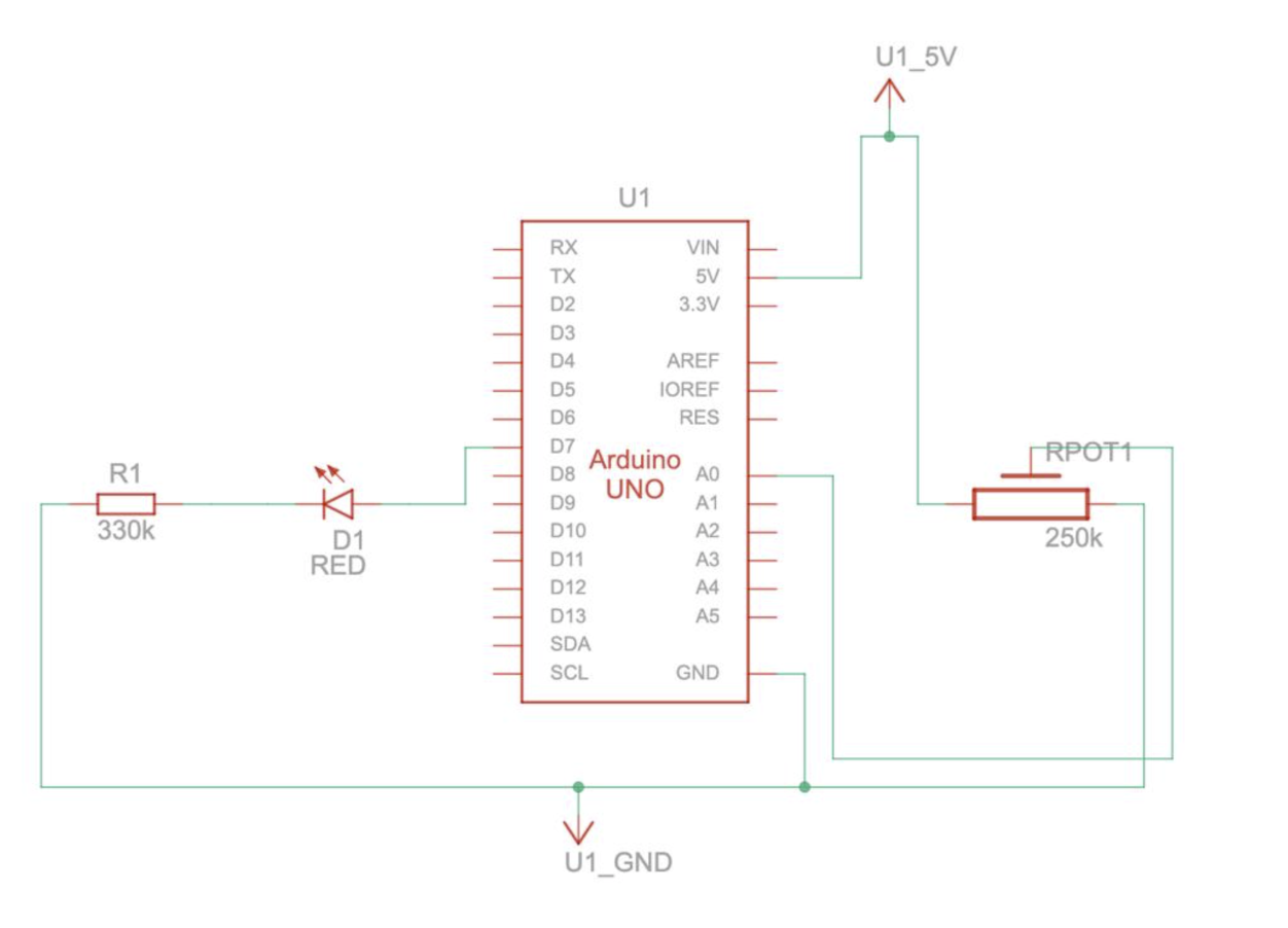
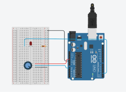
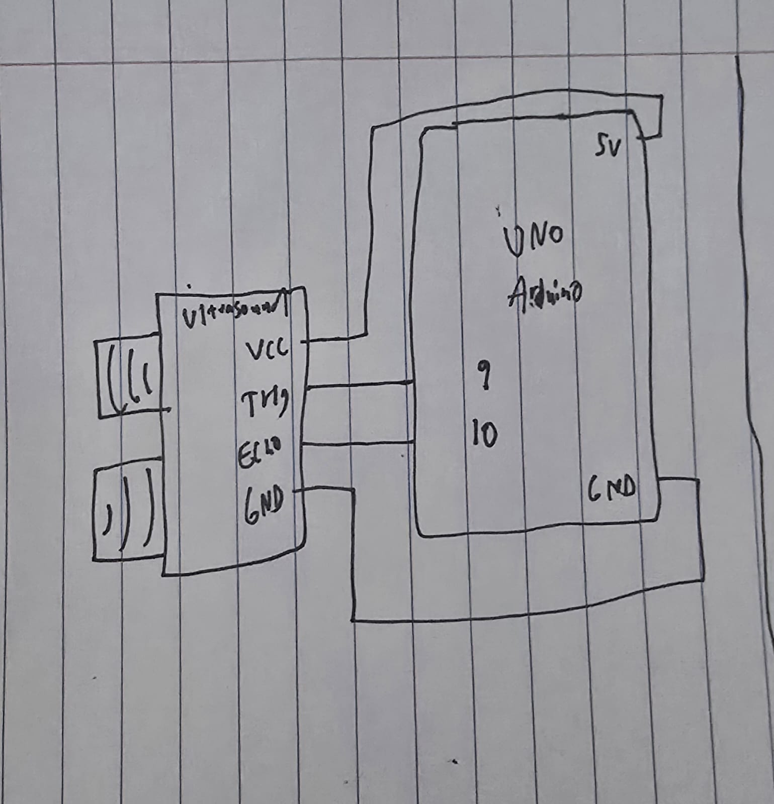
For Exercise 3, used a simple setup of an LED, a 330 ohm resistor and an ultrasonic sensor. The core logic is the LED is by default on and turns off for the split second when the ball touches the ground giving a blinking effect. The wind is mapped to the distance detected by the sensor. A distance of less than 40cm cause left winds and vice versa. The wind strength is proportional to the distance. The ball is meant to bounce off the walls. There is some issue about the right wall, we couldn’t fix it because of lack of understanding of the velocity method.
The arduino code is rather simple, if an object is detected the distance is written to the serial communication, and if an input is read on serial communication the light is blinked. The most interesting part about the arduino code is how the distance is measured using the pulse
long duration = pulseIn(ECHO, HIGH, 30000); // 30 ms timeout
On the P5 ending smoothening of the input by the distance sensor was important because otherwise the the was getting abrupt
latestData = lerp(latestData, val, 0.2);
This was suggested by Chatgpt. It defines a number between basically gets an average but using linear interpolation.
The most challenging part of the code was managing the movement of the ball when the bounce is dying off. As in the last second there were a lot of bounces happening. We dealt with that by instead of blinking the LED on each bounce, we kept the led on and just turned it off when the ball was in contact with the ground.
Sketch