Finalized Concept
The project will be an interactive experience where the users physical body state and actions of caring for themselves will be interpreted to the growth of a digital Bonsai tree. The users breathing are monitored to reflect their calmness, interpreted into the growth of the tree. The act of drinking water will serve as hydration of the tree. The physical light conditions of the user’s environment will be reflected on the tree’s lighting conditions. This experience visualizes meditation and self care, turning it into something tangible and fun.
Arduino programs
Analog Input 1: Breathing. A DIY stretch sensor will be worn by the user as a belt around the chest, monitoring rising and falling movements caused by breathing.
Analog Input 2: Light: A photoresistor will be used to monitor the actual light consitions in the users environment.
Digital Input 1: Hydration: Using the hydrtion switch I designed for week 9, physical drinking will connect a circuit and send a digital input.
Serial communication: The arduino will be constantlu reading the information from the sensors and sending the information in a comma seperated string to p5. Thw arduino will be recieving signals from p5 to trigger LED lights when the value of the different conditions fall under a certain threshold, signaling the user to take corresponding action.
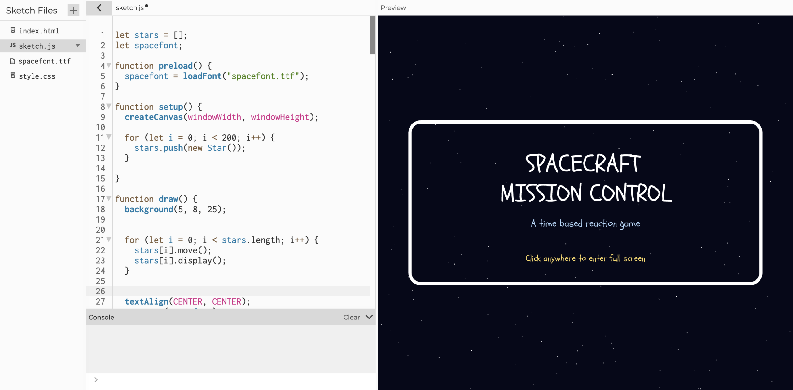
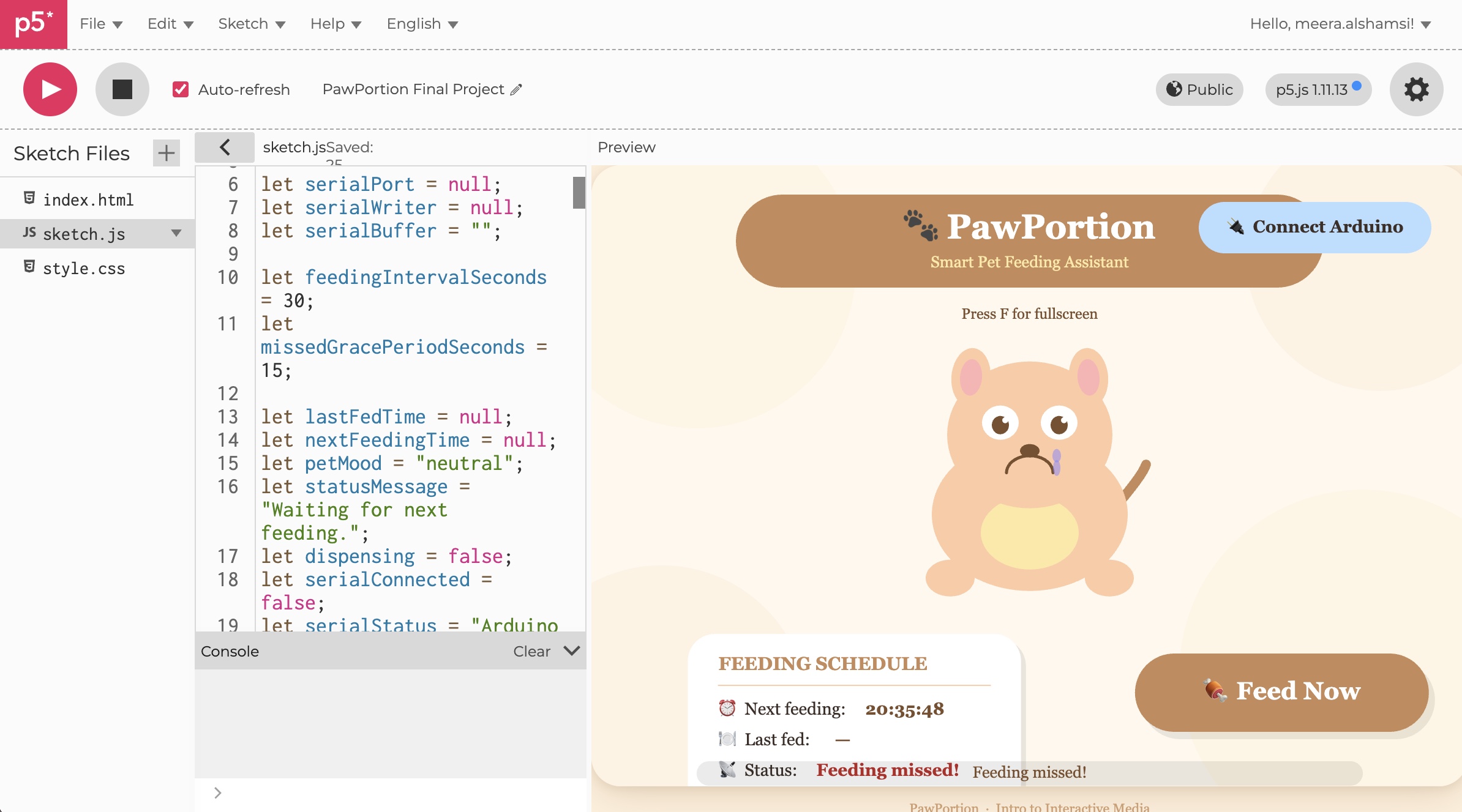
P5 program
P5 will be the actual interface of the experience. Indications of the Bonsais conditions and the Bonsai itself will be shown on the screen. It will also have the function of guiding meditation and breathing. It will receive signals from the arduino and use the data to toggle the trees growth speed, health status, and leaf color.
Serial Communication: P5 will be receiving inputs from arduino, as mentioned above. When hydration, light, or focus of the user (monitored through breathing) falls below 10% of the max value, p5 will send different signals to initiate lighting of different colored LEDs.
Current Progress
I have started building the arduino connections that are possible without the components that are currently in delivery. I also started the initial design of the p5 interface. Serial communication and actual functions hasnt been incorporated because the arduino circuit is not complete yet.
Stipend Breakdown
Conductive rubber cord: ~20RMB
24AWG stranded wire: ~15RMB
Metal LED bezels: ~10RMB
Panel mounted photoresistor: ~10RMB
cardboard: ~15RMB
Shipping for some of the components may cost extra