One idea that stuck with me even after the reading is that eyewear is a space where fashion and disability overlap. The text explains how glasses are no longer seen only as medical tools but also as items people wear to express themselves. This connects to my own experience. When I was younger, I saw my friend’s glasses as more of a fashion statement than something related to vision problems. I would even try them on because I thought they looked good on me. At that time, I didn’t really understand the difference between graded glasses and fashion glasses since they looked similar and came in many styles and colors. It was only later, when I developed farsightedness myself, that I realized their actual purpose. Looking back, I see that my experience reflects what the text describes, that glasses can function both as a medical tool and as a form of self-expression. I also noticed that, as mentioned in the reading, glasses are often visible and even desired, unlike many assistive devices that are designed to be hidden. This shows how eyewear challenges the idea that disability-related products should always be discreet.
On the other hand, I liked how the author pointed out that invisibility is not always the best approach for disability design. Instead of hiding, creating a positive and confident image can change how people see disability. This made me think that trying to make assistive devices invisible can make them seem like something to be embarrassed about. This also made me realize that design doesn’t just solve a problem, it also affects how people feel about themselves and how they are seen by others. A good example of this from the text is Aimee Mullins, who embraces her prosthetic legs and uses them to express herself, similar to how people choose different outfits. Through this example, I realized that design for disability goes beyond just function. It also plays an important role in someone’s confidence, identity, and how people choose to express themselves.
One idea that really stood out to me from Design Meets Disability was the concept of the “golden hand,” especially in the contrast between traditional prosthetics and more expressive designs like Jacques Monestier’s.
What I found interesting is how this shifts prosthetics from something purely functional into something aesthetic and personal. It shows that design doesn’t have to choose between function and beauty it can combine both. As someone with a background in art, this made me think about how designers can transform assistive devices into something meaningful, almost like a canvas for self expression rather than just a medical tool.
Another thing that stood out to me was how the reading emphasizes that artists bring a different perspective to engineering. They focus not just on how something works, but on how it feels and what it represents. This made me reflect on our current Arduino project, where it’s easy to focus only on the technical side, but there’s also potential to incorporate materials and design to make it more visually and personally expressive. The reading also highlights that these designs shouldn’t just be treated as objects, but as personal belongings especially in the case of prosthetics, which are part of someone’s identity. That idea really shifted my thinking, because it suggests design should allow for individuality and expression, rather than trying to hide difference.
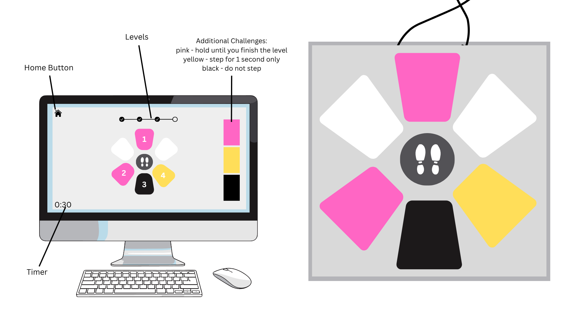
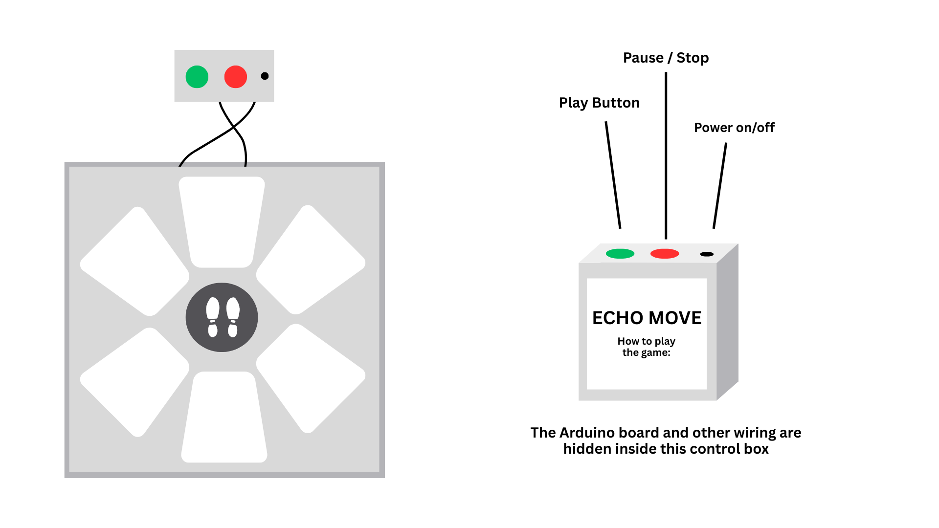
I was inspired by Color Twister, a game where players follow color-based instructions by placing their hands and feet on matching spots. I wanted to take that idea further and make it less about quick reactions and more about thinking, memory, and control, so I came up with Echo Move.
In this game, players are shown a sequence of visual signals on screen for a few seconds. Once it disappears, they have to recall and perform the sequence using their body on the “Echo Move Board,” which is connected to an Arduino. The challenge is to remember the information and use it accurately on time.
Echo Move doesn’t just tell where to step, it also tells the player how to interact. When the pink color appears in the sequence, the player should step into the zone and hold it until the level ends. If it’s yellow, the player should step once and remove it afterward. Holding too long or stepping on it again results in a loss. If it’s black, the player should be aware that it is only for deceit. They should avoid it completely, even if it appears in the sequence. Because of this, players have to interpret each signal before acting. It’s not just about memorizing positions, it’s about understanding instructions, timing movements, and controlling the body.
The game has four levels. Each level gets harder. It adds more complex sequences, tighter timing, and trickier signals. These elements test the player’s memory and decision-making skills.
Another key aspect is that the physical board itself has no colors, only neutral zones. All cues come from the screen, which means players must mentally map what they see onto the board. This adds abstraction. It forces them to turn visual cues into actions without direct help.
P5 and Arduino
In this game, P5 handles the game logic, visuals, and state control, while Arduino handles the physical input.
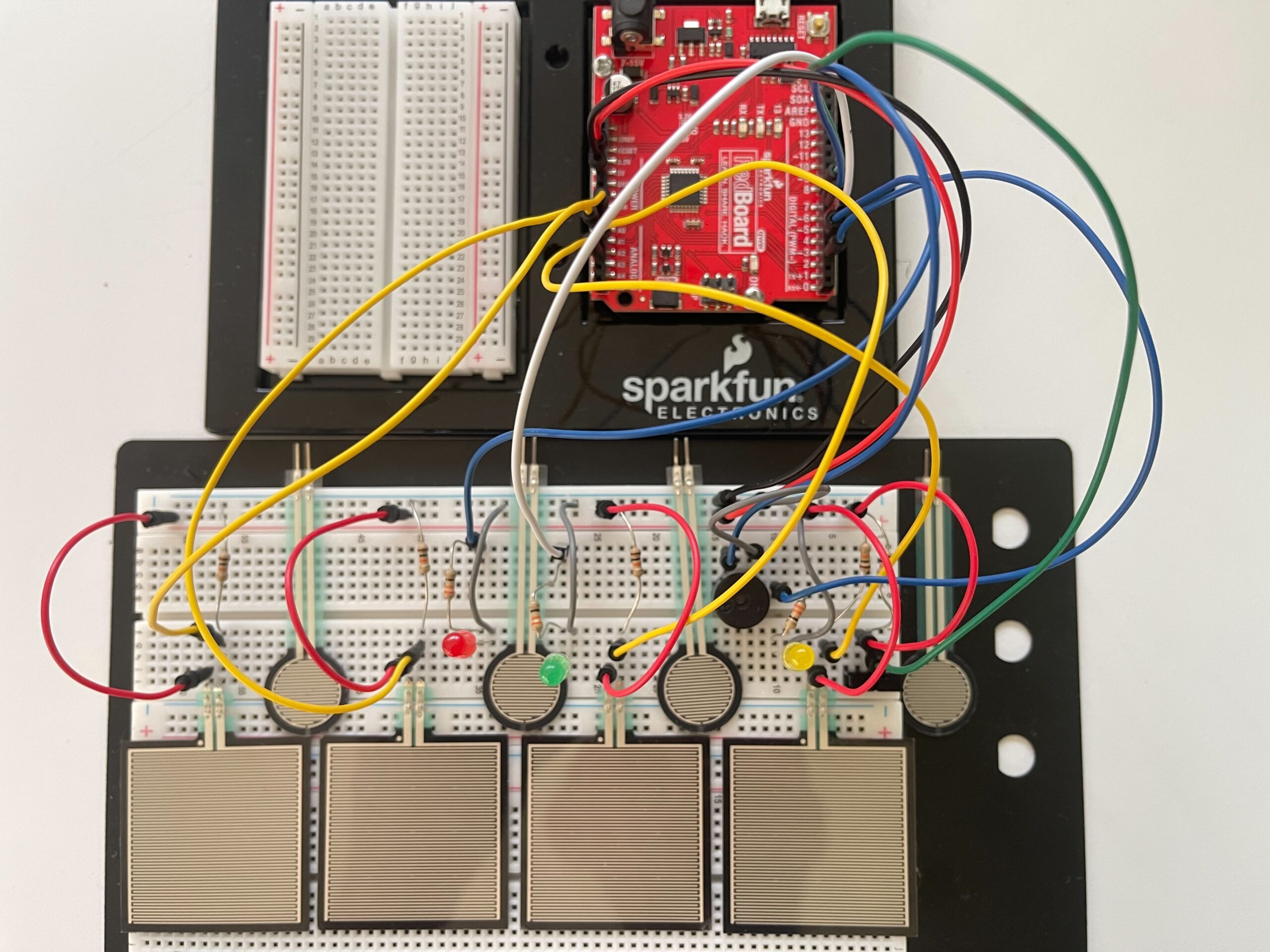
Each zone on the Echo Move board uses force-sensitive resistors (FSRs) to detect when a player presses on it. Arduino constantly reads these sensors and converts them into simple signals, such as pressed or not pressed. In addition to the FSR sensors, the Arduino will also read inputs from physical buttons connected to the system, including on/off, play, and pause/stop. These buttons control the state of the game and send signals to P5 when pressed. Arduino then sends all input data to P5 through serial communication in real time.
The P5 program, on the other hand, controls the game logic and what the player sees on screen. It displays the sequence of colors and signals that the player needs to remember. After a few seconds, the sequence disappears, and the player must perform it on the board. As Arduino sends input data, P5 reads both the sensor inputs and button signals. The buttons are used to control the flow of the game, such as starting, pausing, or stopping. P5 then checks if the player is following the correct order, timing, and actions, such as holding, tapping, or avoiding certain zones. Based on this, P5 decides if the player wins or loses and can send a message back to Arduino to control the game state.
Stipend Usage
I’ll be using my stipend to buy the main parts I need for the Echo Move board, especially the force-sensitive resistors (FSRs) and longer jumper wires. These will help me properly detect player input and make sure the connections across the board are stable and flexible.
Preliminary Concept: Pressure-Based Digital Instrument
For my final project, I plan to create a physically interactive musical instrument using Arduino and p5.js. The idea is to build a simple keyboard-like interface where users can play notes by touching pressure sensors.
Instead of using buttons, I will use Force Sensitive Resistors (FSRs) so that the interaction feels softer and more natural, similar to placing fingers on a piano. Each sensor will represent one note (C, D, E, F, G, A, B, C, including sharps/flats). Below picture will have only 4 FSR406 and 4 FSR402, I will buy them more and also 16 channel analog multiplexer to complete my project soon.
Arduino will read the sensor values and send the data to p5.js through serial communication. In p5, the input will be used to generate sound and simple visual feedback. I will use the computer’s speaker for audio output instead of a buzzer to improve sound quality.
Since I need to use multiple sensors, I will use a CD74HC4067 multiplexer to expand the number of inputs. This allows Arduino to read many FSRs efficiently.
The system will also include a feedback loop. For example, when a note is played, p5 can send a signal back to Arduino to turn on an LED. This creates a simple two-way communication between Arduino and p5.
The goal of this project is to explore how physical touch can be translated into digital sound and visual feedback in a clear and responsive way.
Inspiration
This project is inspired by different types of interactive musical interfaces:
* Digital MIDI controllers and touch-based instruments
* Piano keyboards, especially the idea of soft and responsive touch
* Interactive installations where physical actions directly control sound
* Simple expressive systems that focus on user interaction rather than complexity
I am particularly interested in how small physical gestures, like lightly touching a surface, can create meaningful digital outputs such as sound.
References / Tutorials
Here are some references and tutorials that informed my idea:
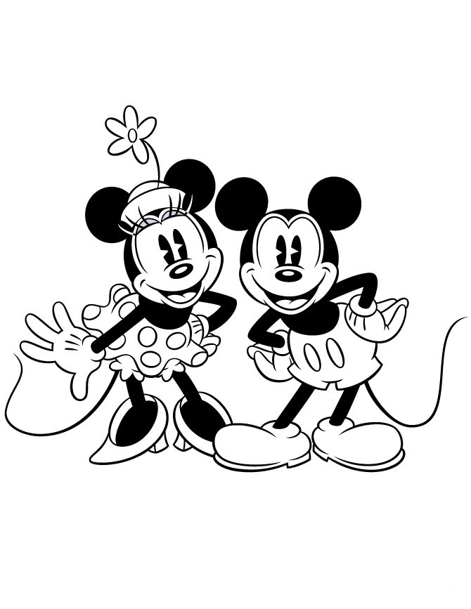
For my final project, I am creating a physically interactive maze game that uses both Arduino and P5.js. So I decided to pick minnie mouse and mickey mouse as my two characters. The idea is to guide minnie mouse through a maze using two physical potentiometers instead of a keyboard or mouse. The player’s goal is to move minnie mouse from the start of the maze to the end, where mickey mouse is waiting.
The interaction works in a simple cycle of listening, thinking, and responding. The Arduino will be the “listener” because it reads the positions of the two potentiometers. One knob controls left andright movement, and the other controls up and down movement. When the player turns the knobs, Arduino senses the changes and sends those values to P5.js. P5. will be the “thinker,” because it takes those values and turns them into movement on the screen. The game then responds by moving the character in real time and showing whether the player is controlling minnie mouse in staying inside the maze or hitting the walls. I want to consider adding a celebration melody when minnie mouse reaches mickey mouse. I might as well make the LED blink when Minnie hits a wall to alert the player about it.
The maze itself will be drawn in P5 using simple shapes or a custom layout. I will have a start screen and instructions screen. The character will move smoothly through the pathways, and basic collision detection will prevent it from passing through walls. When the player reaches the goal area, the game will display a small celebration animation or visual cue to show that the objective has been completed. The experience is meant to feel playful, fun and slightly challenging, since the player must learn how to control movement using physical knobs instead of controlling it with the laptop. I will probably take photos of minnie mouse and mickey mouse of the internet and use them as my characters.
Reading Design Meets Disability made me rethink what I previously considered “good design.” I used to associate good design with aesthetics and general usability, but this reading challenged my assumption by showing how design is deeply tied to social attitudes toward disability. The section on “discretion” stood out to me, where assistive devices like hearing aids are designed to be hidden in order to avoid stigma. This made me question whether invisibility is actually a positive goal, or if it reinforces the idea that disability should be concealed. I found myself reflecting on how design choices are not neutral and that they reflect cultural values about what is considered “normal.” The tension between fashion and disability also left a strong impression on me. While making assistive devices more fashionable can empower users, it also risks emphasizing appearance over accessibility. This contradiction made me realize that design often operates between competing goals rather than clear solutions.
This reading also connected to my previous understanding of user-centered design but expanded it in a way I had not considered before. It made me realize that “the user” is often imagined as a narrow, able-bodied group, which doesn’t take into account many real experiences. The idea of “simple meets universal” raised an important question for me that is it actually possible to design something that works for everyone, or does inclusivity inevitably introduce complexity? This challenges the assumption that simplicity is always better. Personally, this reading shifted my perspective from seeing design as purely functional problem-solving to understanding it as a more cultural and ethical practice that shapes how people are perceived and included. It also made me more aware of the limitations in the designs I encounter daily and how they really reflect broader biases rather than just technical decisions.
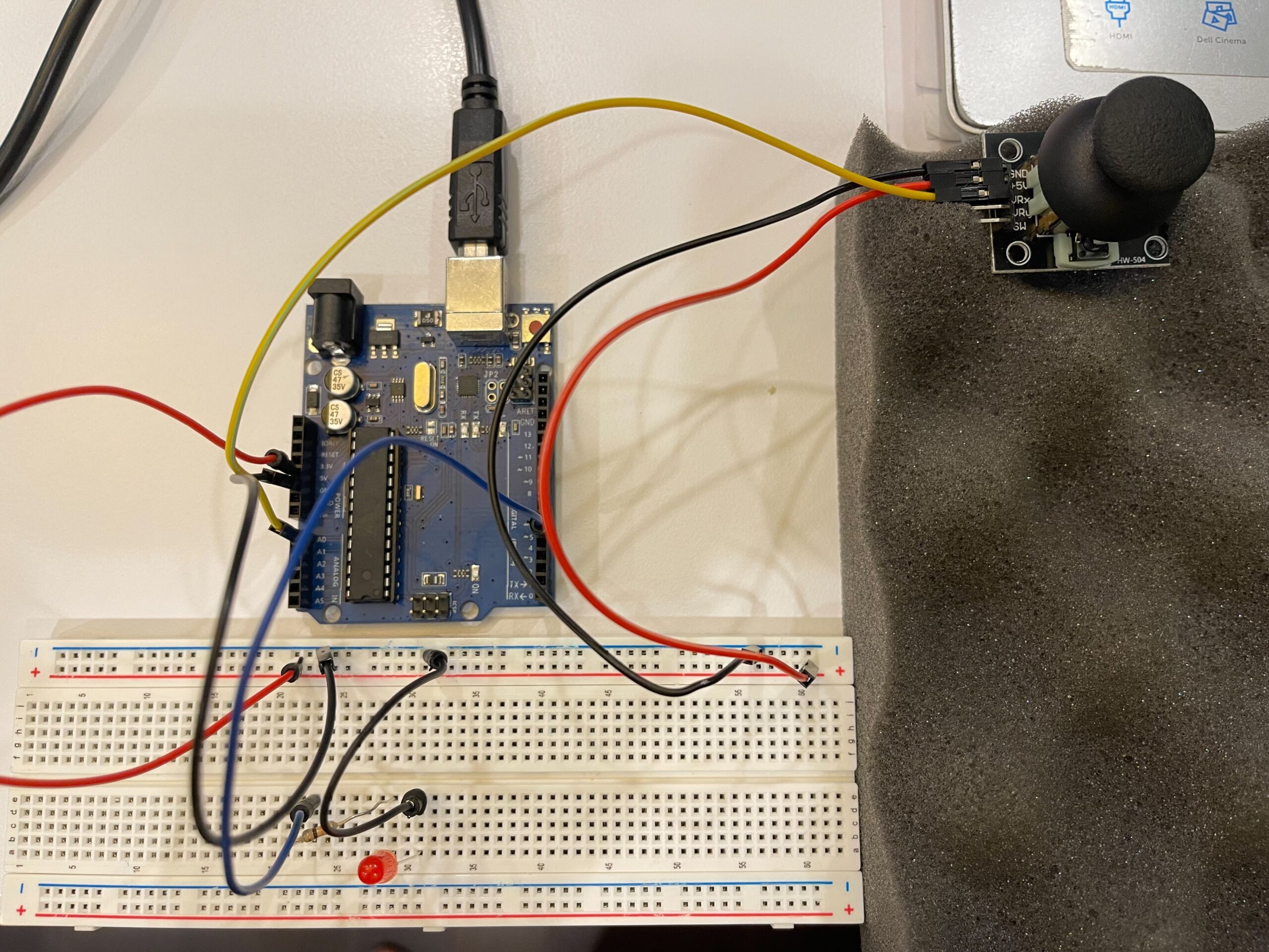
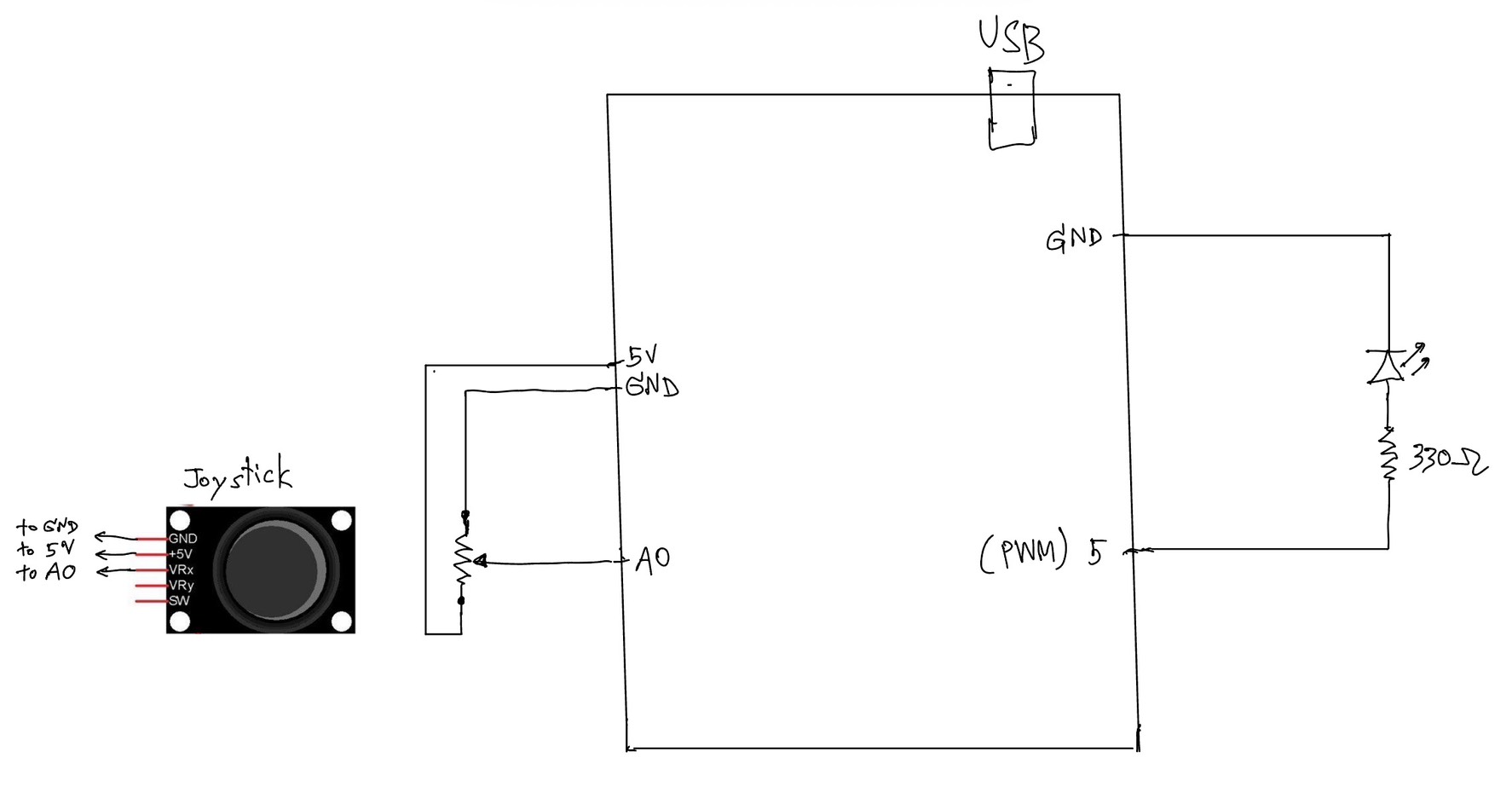
In this exercise, we extended our work from the previous tasks by implementing bi-directional communication between Arduino and p5.js. The goal was to use an analog sensor to control the wind force in a physics simulation, and at the same time send data back from p5 to Arduino to control an LED.
We started from the gravity and wind example provided in class and kept the structure mostly unchanged. Instead of using keyboard input to control the wind direction, we replaced it with a joystick connected to Arduino. The horizontal axis of the joystick was read using analogRead() and sent to p5 through serial communication.
On the p5 side, the incoming value was read using port.readUntil(“\n”), then converted into an integer. We mapped this value to a range between -1 and 1, which was used as the horizontal wind force. As a result, moving the joystick left or right directly influenced the movement of the ball in the simulation.
To complete the bi-directional interaction, we added a simple condition in p5 to detect when the ball bounces on the ground. Whenever a bounce occurs, p5 sends a value back to Arduino. On the Arduino side, this value is read using Serial.parseInt(), and the LED is turned on or off accordingly.
This allowed us to create a system where Arduino sends sensor data to p5, and p5 responds by sending control signals back to Arduino.
⸻
What We Learned:
* How to implement bi-directional serial communication
* How to use an analog sensor (joystick) to control a physics simulation
* How to send control signals from p5 back to Arduino
* How physical and digital systems can interact in both directions
⸻
Code I’m Proud Of:
One part we are particularly satisfied with is how the system detects a meaningful bounce and avoids triggering unnecessary signals.
p5.js (bounce detection + sending data)
let bounced = 0;
  let floorY = height - mass / 2;

  // bottom bounce
  if (position.y > floorY) {
    position.y = floorY;

    if (velocity.y > 2) {
      velocity.y *= -0.9;
      bounced = 1;
    } else {
      velocity.y = 0;
    }
  }

  // send LED state back to Arduino
  if (port.opened()) {
    port.write(bounced + "\n");
  }
This section is important because it defines what counts as a “real” bounce. By using a velocity threshold, we ensure that only stronger impacts trigger the LED, while small movements at the ground are ignored.
⸻
Arduino (receiving and controlling LED)
int ledState = Serial.parseInt();

    if (Serial.read() == '\n') {
      digitalWrite(ledPin, ledState);
    }
This part connects the digital signal from p5 to a physical output. It shows how a simple value sent through serial communication can directly control hardware.
Challenges:
One issue we encountered was that the LED flickered rapidly when the ball reached the ground. Even though the ball appeared to be at rest, the system continued to detect small movements due to gravity and drag.
At first, this made the LED stay on or flicker continuously, which was not the intended behavior.
To solve this, we introduced a simple velocity threshold. Instead of triggering a bounce whenever the ball touched the ground, we only considered it a valid bounce when the downward velocity was greater than a certain value. After testing, we found that using a condition of velocity.y > 2 provided a stable and clear result.
This helped us better understand how physics simulations can produce small continuous movements, and why additional conditions are sometimes needed to define meaningful events.
⸻
Future Improvements:
If we were to continue developing this project, we would consider:
* Adding a dead zone to the joystick to reduce unwanted drift
* Using both axes of the joystick to control more complex motion
* Adding more LEDs or outputs to represent different events
* Improving the visual feedback to better match the physical response
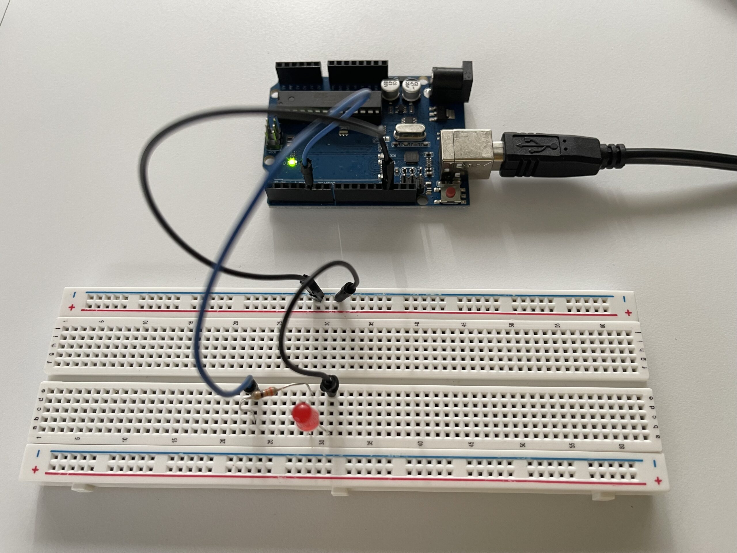
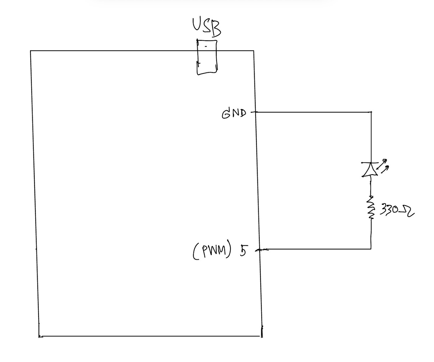
In this exercise, we explored serial communication in the opposite direction, from p5.js to Arduino. The main objective was to control the brightness of an LED on Arduino using an interaction created in p5.
We again started from the class example and kept the overall structure close to what was introduced by professor Aya. However, for this exercise, we simplified the communication so that p5 sends only one value instead of multiple values. This made it easier to focus on the main idea of sending data from the browser to Arduino.
On the p5 side, we used the p5.webserial library and the same button-based connection method as in the previous exercise. Once the serial connection is opened, p5 continuously sends a brightness value based on the horizontal position of the mouse. This value is mapped into a range between 0 and 255, which matches the range used by analogWrite() on Arduino.
On the Arduino side, we used Serial.parseInt() to read the incoming integer sent from p5. After checking for the newline character \n, the value is applied to an LED connected to a PWM pin. This allows the LED to gradually brighten or dim instead of simply turning on and off.
This exercise helped us better understand how p5 can be used not only to receive data from Arduino, but also to actively control physical outputs on the hardware side. Compared to Exercise 01, this made the communication feel more interactive because the browser was no longer only displaying data, but also sending instructions back to Arduino.
Through this process, we gained a clearer understanding of how serial data can be used to control physical output in real time, and how important it is for both the code structure and the wiring to match the intended behavior.
⸻
What We Learned:
* How to send data from p5.js to Arduino through serial communication
* How to use Serial.parseInt() on the Arduino side
* How to control LED brightness with analogWrite()
* How browser-based interaction can directly affect hardware output
Code I’m Proud Of:
One part we are particularly satisfied with is how the p5 sketch and Arduino sketch work together to control LED brightness in real time. This section clearly shows how a visual interaction in the browser becomes a physical output on the Arduino side.
p5.js (sending brightness value)
let brightness = int(map(mouseX, 0, width, 0, 255));
  brightness = constrain(brightness, 0, 255);

  // show the current value on screen
  fill(brightness);
  rect(100, 150, 200, 100);

  fill(0);
  textSize(16);
  text("Brightness: " + brightness, 120, 130);

  if (port.opened()) {
    port.write(brightness + "\n");
  }
This part is meaningful because it translates a simple mouse movement into a numerical value that can be understood by Arduino. It also helped us see how p5 can act as the controlling side of the communication.
⸻
Arduino (receiving + controlling LED)
int brightness = Serial.parseInt();

    if (Serial.read() == '\n') {
      analogWrite(ledPin, brightness);
    }
We found this section especially important because it shows how Arduino receives a value from p5, processes it, and immediately applies it to a physical output. In this case, the output is the LED brightness controlled through PWM.
Problems We Encountered:
One issue we encountered was that the LED did not appear to brighten or dim smoothly at first. Even though the value on the p5 side was clearly changing, the LED response did not look correct. After checking both the code and the circuit, we realized that the LED needed to be connected to a PWM pin in order for analogWrite() to work as expected. Once we moved the LED to the correct pin, the brightness control became much more visible.
Another thing we paid attention to was keeping the communication format simple. Since this exercise only required brightness control, we kept the message to a single value followed by a newline character. This made the program easier to understand and reduced confusion while testing.
⸻
Future Improvements:
If we were to continue developing this exercise, we would consider:
* Replacing mouse control with a more interesting p5 interaction, such as dragging, key presses, or etc.
* Adding multiple LEDs and sending more than one value from p5
* Expanding the system into bi-directional communication so Arduino could also send sensor data back to p5
* Improving the visual design in p5 so that the screen feedback more closely matches the physical LED behavior
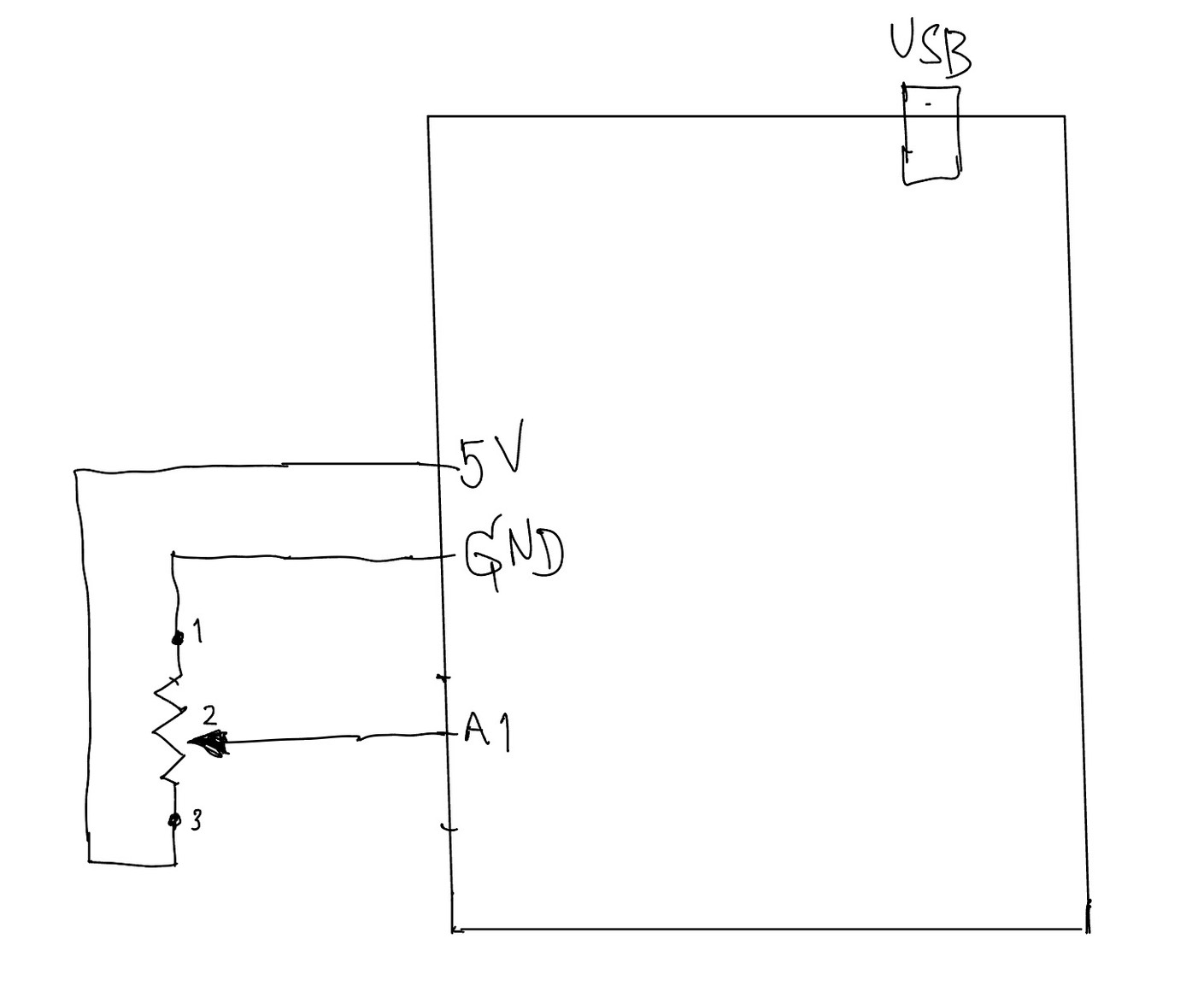
In this exercise, we explored serial communication between Arduino and p5.js. The main objective was to use a single sensor on Arduino and translate its input into visual movement in p5, specifically controlling an ellipse moving horizontally across the screen.
We began by following the example demonstrated in class and gradually adapted it to better understand the data flow. On the Arduino side, we used a potentiometer as an analog input. The sensor value (0–1023) was mapped to a smaller range (0–255) before being sent through the serial port using Serial.println(). This ensured that the data could be easily interpreted on the p5 side.
For p5.js, we adopted the structure introduced by professor Aya using the p5.webserial library. The connection process is handled through a button (connectBtn), and the serial port is opened using port.open(baudrate). This approach helped us clearly understand how communication between Arduino and the browser is initiated manually rather than automatically.
Inside the draw() loop, we used port.readUntil(“\n”) to read incoming serial data line by line. The received string is then cleaned and converted into a number using trim() and int(). We then used map() to convert this value into a position across the canvas width. As a result, the ellipse moves smoothly from left to right, and when the input value decreases, it naturally moves back from right to left, creating a responsive and continuous motion.
Through this process, we gained a clearer understanding of how physical input can directly influence digital visuals in real time. It also highlighted the importance of consistent data formatting and timing in serial communication.
⸻
What We Learned
• How to send analog data from Arduino using Serial.println()
• How to receive and interpret serial data in p5.js
• How to map sensor values into visual output
• How hardware and software can interact in real time
⸻
Code I’m Proud Of
One part we are particularly satisfied with is how the sensor data is processed and translated into visual movement. This section demonstrates how raw data from Arduino becomes meaningful interaction in p5.
int potentiometer = analogRead(A1);

 // map the value from 0-1023 to 0-255
 int mappedPotValue = map(potentiometer, 0, 1023, 0, 255);

 // send value to p5 as a string with newline
 Serial.println(mappedPotValue);
This part is important because it simplifies the raw sensor data into a range that is easier to use on the p5 side.
⸻
let str = port.readUntil("\n");

if (str.length > 0) {
  let val = int(trim(str));   // convert string → number

  // map value to screen position
  x = map(val, 0, 255, 0, width);
}
We found this section especially meaningful because it clearly shows the full pipeline: sensor → serial → processing → visual output.
⸻
Future Improvements
If we were to continue developing this project, we would consider:
• Using different sensors such as FSR or ultrasonic sensors for more dynamic interaction
• Adding smoothing to reduce noise in sensor readings
• Expanding the visuals to control multiple elements instead of a single ellipse
• Exploring bi-directional communication between Arduino and p5
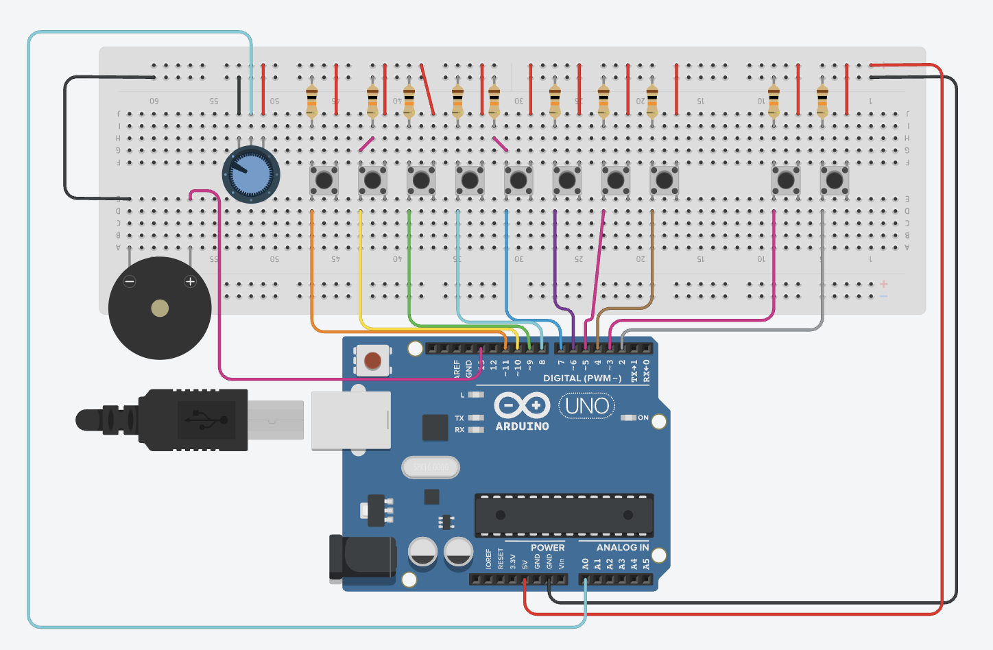
When I heard the sound of the button in class on Thursday, the intro of this song INSTANTLY popped in my head (first 10-15 seconds, becomes a repeating riff):
Hence, you can imagine where I’m going with this.
Concept:
This felt very self-indulgent, but I’m a piano/keyboard and electric guitar/bass player, hence I wanted to make something I could actually play by pressing things, like the instruments. While I didn’t originally have any intention for analog sensors, I thought I could use the potentiometer to control the “piano” sounds and make them vibrate a bit. I also wanted to be able to play the intro to this song with the notes, and also have an option to listen to it through the instrument (when I’m too lazy to play myself… haha). Usually I have more to say for the concept, but this time, I felt very monkey-brained, especially since I still get confused with arduino: I hear sound, I associate to something else, I make based on this, ta-daa!
Circuit Demonstrations (please ignore the fact that there’s no cursor, I recorded these on my iPad):
Song Button:
Individual Buttons:
Process:
This took me quite a while to do manually, but let’s go step-by-step.
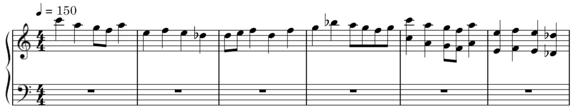
ONE: Find the notes of the song (or part of the song) you want.
While I would have liked to do this with my piano, I 1) don’t have my piano with me and 2) don’t have enough time, so I went online and searched for a sheet music of the intro part of the song.
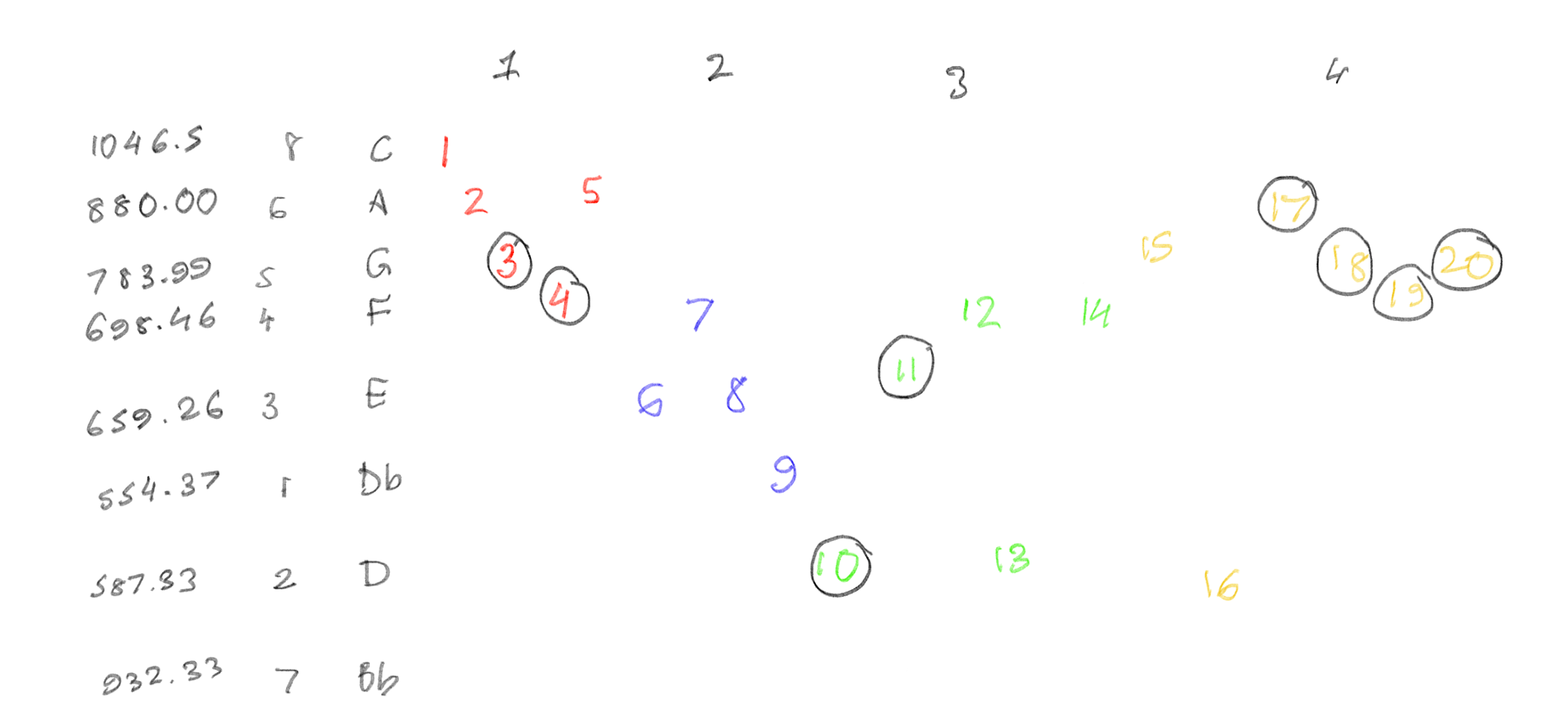
I found this on musescore, and found out how many notes were there (8 notes: C6, B♭5, A5, G5, F5, E5, D5 and D♭5). From there, I then wrote down the order in which each note came, and how long each note was.
I split each bar by color, and circled all the notes which were quavers (1/2 shorter than the un-circled notes). Then, using this chart, I also marked each frequency. After figuring this out, I then started creating the circuit.
TWO: … make the circuit.
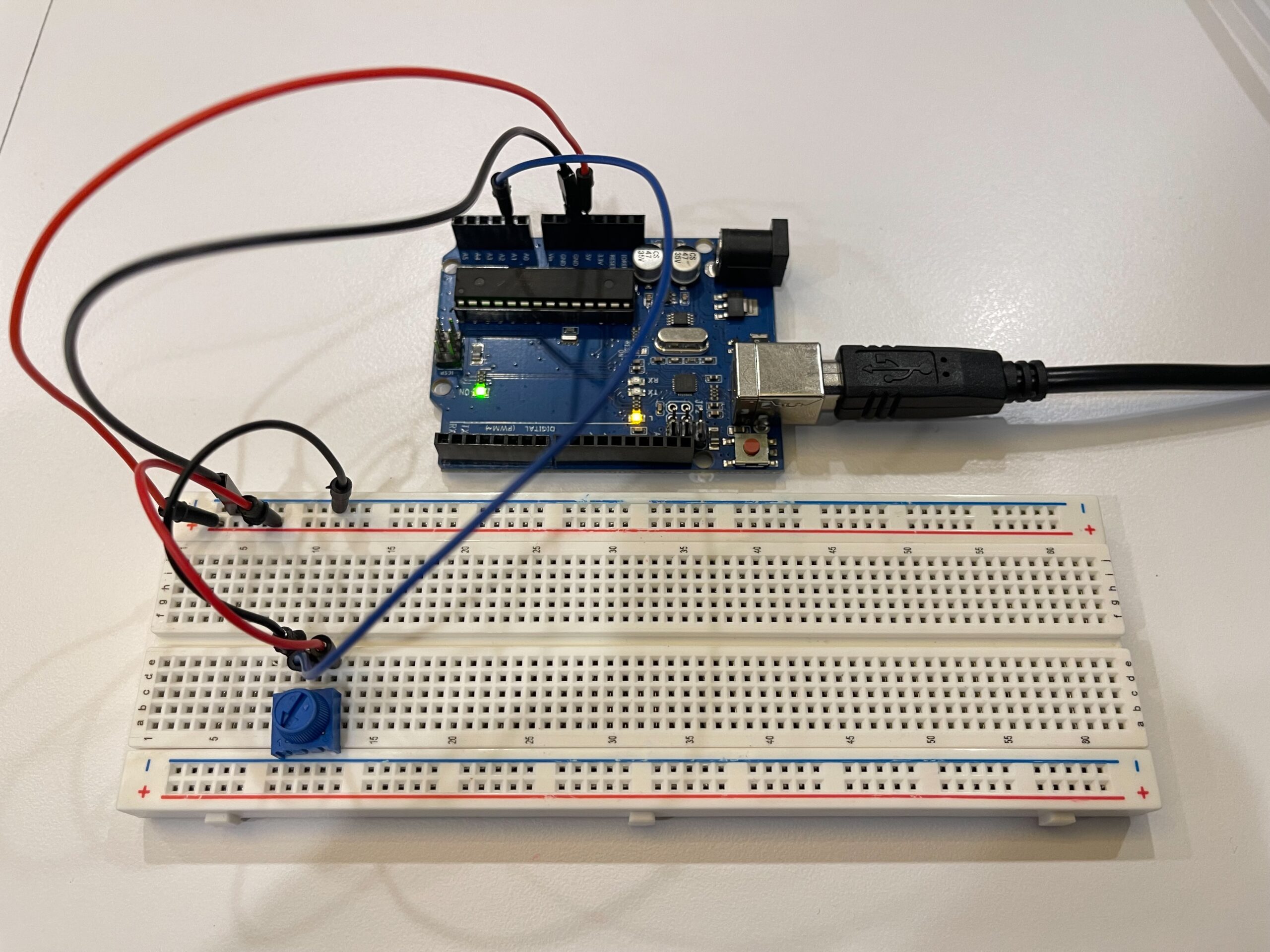
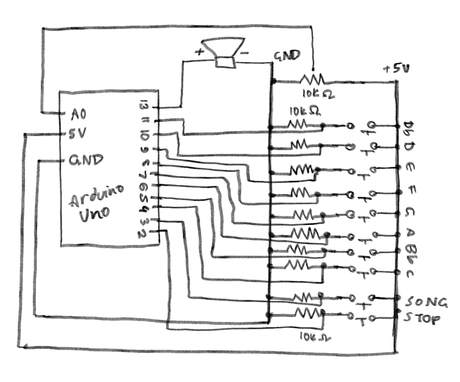
Making the circuit was pretty straightforward. I did opt for a larger breadboard than I usually do (just to fit all the keys), and one thing that did frustrate me was the spacing of the ground and voltage dots on the board (DIAGONAL WIRES???). I had to play around with the spacing of the buttons quite a lot, but otherwise, everything fit well.
THREE: Spend a few hours coding. And coding. And coding a bit more. Oh, wait, you missed a comma- I’ll break my code down lines-by-lines, mainly the parts that make this the instrument (or else I’ll end up breaking everything down).
I defined each frequency I calculated as the note to prevent me from having to type each decimal again and again. I used speedMultiplier because later on in the code, I messed up the speed at which to play the notes (so just temporarily ignore that). StaccatoMultiplier was so I could reduce the length of the note, as the original song has the sound very short and crisp for most notes. I then assigned all of the hardware attached to the Arduino.
I coded the song for the second last button (on the circuit). (I was really proud of this part) I had to write down the order of notes first, and then pick out durations for each note in ms. (400 is crotchets, 200 is quavers).
const int introNotes[] = {
  C6, A5, G5, F5, A5,
  E5, F5, E5, DF5,
  D5, E5, F5, D5, F5,
  G5, B5, A5, G5, F5, G5,
  C6, A5, G5, F5, A5,
  E5, F5, E5, DF5,
  D5, E5, F5, D5, F5,
  G5, B5, A5, G5, F5, G5
};

const int introDurations[] = {
  400, 400, 200, 200, 400,
  400, 400, 400, 400,
  200, 200, 400, 400, 400,
  400, 400, 200, 200, 200, 200,
  400, 400, 200, 200, 400,
  400, 400, 400, 400,
  200, 200, 400, 400, 400,
  400, 400, 200, 200, 200, 200
};

const int INTRO_LEN = 40; // total of 40 notes
int introTimings[40]; // array to store when each note starts
int totalIntroTime = 0;
bool playingIntro = false; // to make sure it doesn't play without pressing button
unsigned long introStartTime = 0;
For setup(), I made sure that the speaker was silent at startup. When I was originally coding, every time I would run the simulation, my ears would blast at the random sounds coming, and I needed to remove that. runningTime was when the song would start playing, and to calculate when to play each note after this, the code would calculate such that:
void setup() {
  noTone(PIEZO);
  for (int i = 0; i < 8; i++)
    pinMode(buttons[i], INPUT);
  pinMode(PIEZO, OUTPUT);
  pinMode(BTN_PLAY_INTRO, INPUT);
  pinMode(BTN_STOP_INTRO, INPUT);

  int runningTime = 0;
  for (int i = 0; i < INTRO_LEN; i++) { // for each of the 40 notes
    introTimings[i] = runningTime; // remember when THIS note starts
    runningTime += (int)(introDurations[i] * speedMultiplier); // because I needed to fix the speed LOL
  }
  totalIntroTime = runningTime;
}
I noticed I was having an issue where when I would play each note in the song, I would have a note in between which didn’t fit. To fix this, I used this:
int currentNote = -1; // start with no note
      for (int i = 0; i < INTRO_LEN; i++) {
        if (elapsed >= introTimings[i] && elapsed < (introTimings[i] + (int)(introDurations[i] * speedMultiplier * staccatoMultiplier))) {
          currentNote = i;
          break;
        }
      }

      if (currentNote == -1) {
        noTone(PIEZO); // silence if no note matches current time
      } else {
        tone(PIEZO, (int)introNotes[currentNote]);
      }
The loop would find a note that matches the current time for the next note, and if no note matches the time window for the specific note, it would continue not playing (remains -1) and make it silent until the next note.
Then, here, I edited the vibrato of the note with it (how shaky or pure the note is). This code has that, and also code to stop the song from playing if you play any other note on the piano. The vibrato is only heard on the individual button notes, not the programmed song.
// stopping the music

for (int i = 0; i < 8; i++) {
      if (digitalRead(buttons[i]) == HIGH) {
        playingIntro = false;
        noTone(PIEZO);
        break;
      }
    }
  }
// individual button mode (no music)

if (!playingIntro) { //only not intro
    float vibratoHz = map(analogRead(POT), 0, 1023, 1, 20);
    float vibratoDepth = 20;

// calculate vibrato as a sine wave
    unsigned long now = millis(); // current time
    float offset = sin(2.0 * 3.14159 * vibratoHz * now / 1000.0) * vibratoDepth;
    // oscillate between -20 and +20, not too much
    bool anyPressed = false; // any piano note pressed
    for (int i = 0; i < 8; i++) { // look through which button is pressed
      if (digitalRead(buttons[i]) == HIGH) {
        int finalFreq = (int)(baseNotes[i] + offset); // play the note with vibrato
        tone(PIEZO, finalFreq);
        anyPressed = true;
        break;
      }
    }
    if (!anyPressed) noTone(PIEZO);
  }
}
Schematic:
Reflections:
I’m glad it came out well. I was worried I’d mess this up and wouldn’t be able to hear the sound, especially with all the fumbles in between such as loud sounds that weren’t coded, or bad timing of the notes. I’m also glad that not only the song worked, but so did the notes! I didn’t expect the vibrato to actually work out so you can actually hear it clearly. I had a lot of fun making this. ദ്ദി(。•̀ ,<)~✩‧₊
I do feel like I could have added more things for it to come out the way I would further envision it. I wanted to put LEDs to light up every time you press a button (but was worried about breadboard space), those LED displays to show something while the song played (but didn’t want to venture there just yet), and include a way for people to add on the rest of the song’s instruments, like the drums and guitar (but didn’t know how to do it on TinkerCad). Hopefully I can implement these in my final project! 🙂


