Finalized concept for the project
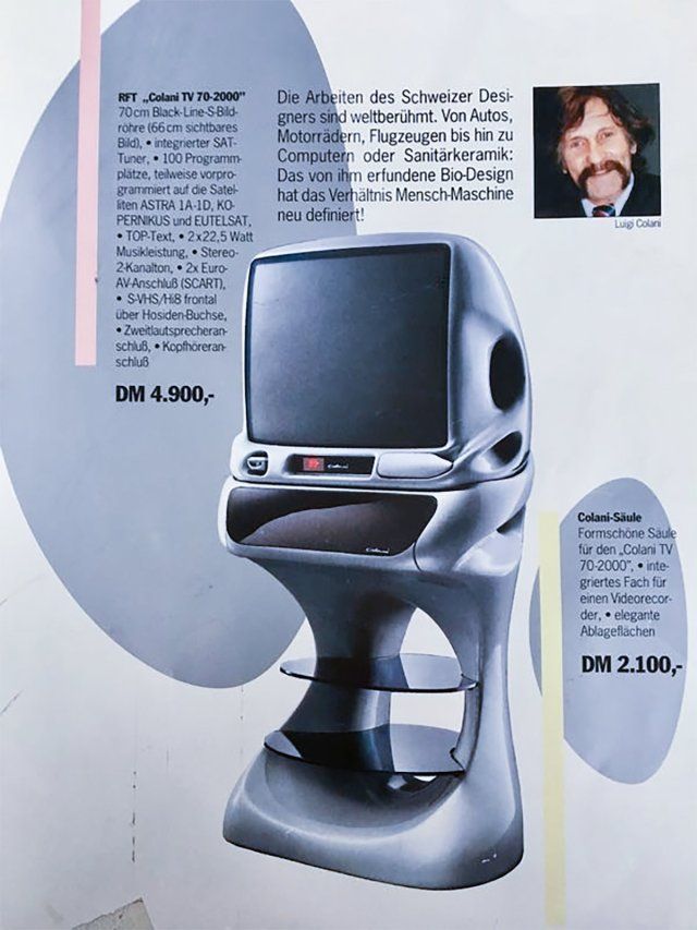
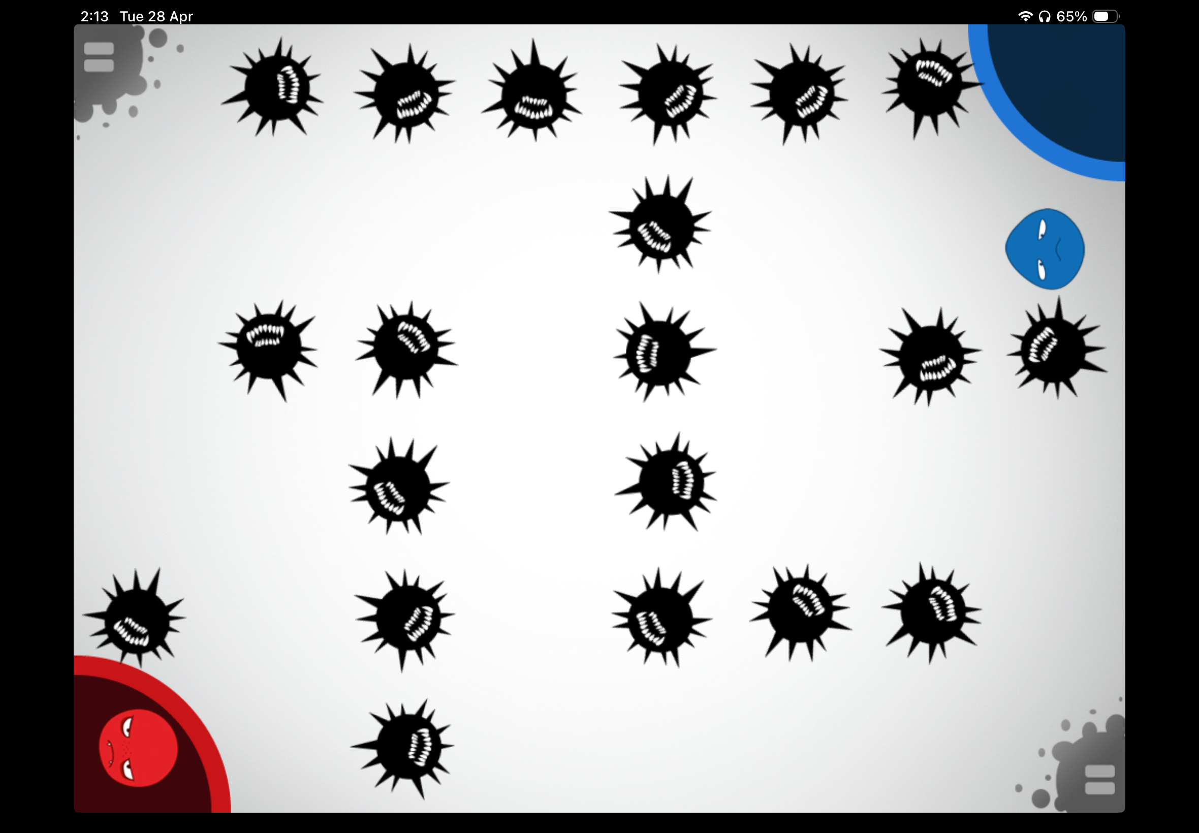
My idea for the final project is inspired by a game I used to play a lot as a kid, Virus vs Virus. It’s not a very popular game and can only be played on iPad, so I’ll include some images & videos below of the gameplay to give an idea of my inspiration. To summarize, Virus vs Virus is a multi-player game that consists of many mini-games, the mini-games range from memory games, mazes games, and speed games. It has over 10 mini-games that are all pretty straightforward.
I want to reimagine the game in a physical way and integrate at least three mini-games into my final project. The general idea is still the same, it would be a multiplayer game and the winner is whoever wins the most mini-games. I plan on re-creating 3-4 mini-games and probably edit them to match a physical implementation. I anticipate needing to order more components, such as a joystick controller. I also want to use different characters (not viruses!), and so far, the main idea I have in mind is inspired by an Instagram creator who creates mugs inspired by people’s faces. However, my game would probably not have customizable features but rather just 2-4 static characters to choose from.
The specific games I’m thinking of implementing are below. I would love to implement additional games, however, for now, I’m trying to narrow it down to keep it more achievable and less overwhelming. For each one, I’ve included a short description of what this would look like:
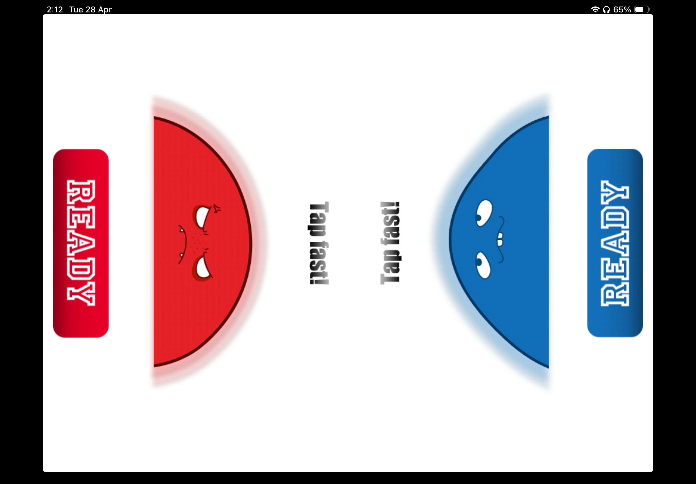
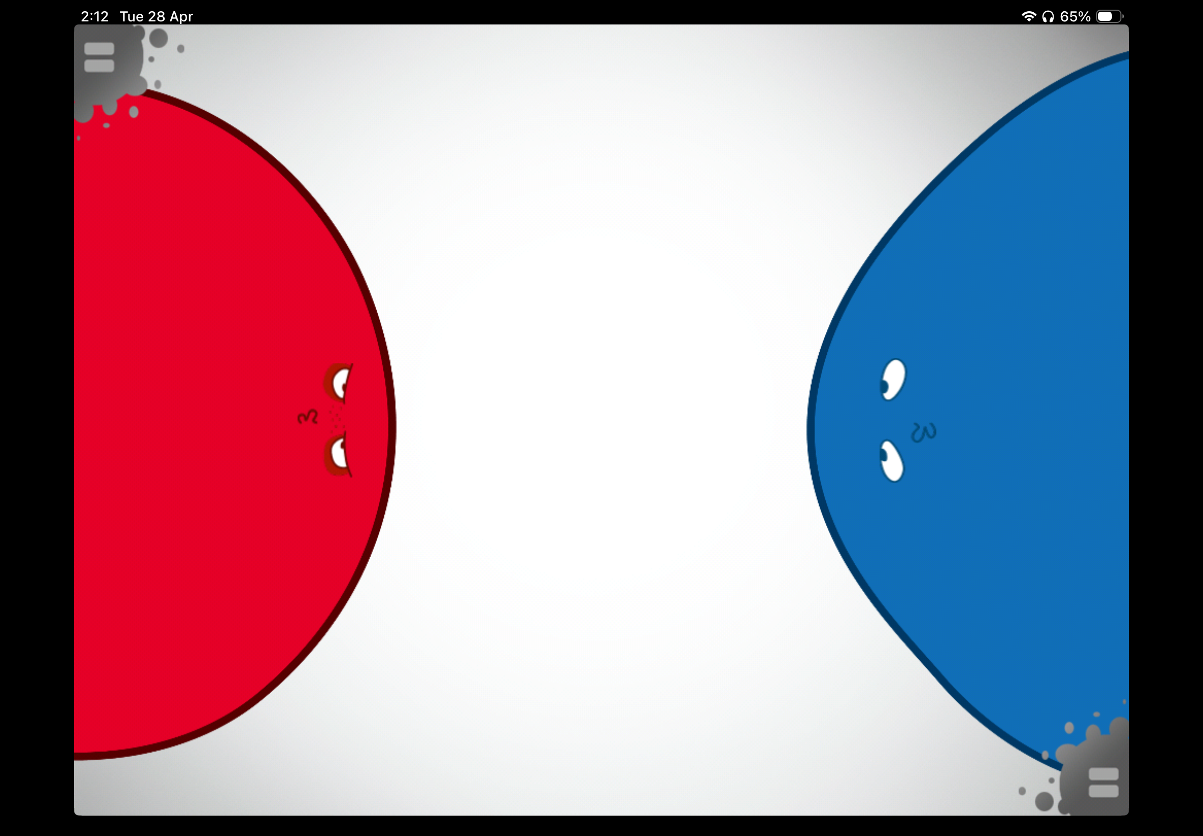
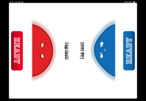
The first game consists of the users tapping as fast as they can on their virus for it grow to the largest size. The virus that fills up the full screen first is the winner. I hope to redesign this game using the Arduino by using either buttons or possibly, the ultrasonic sensor.

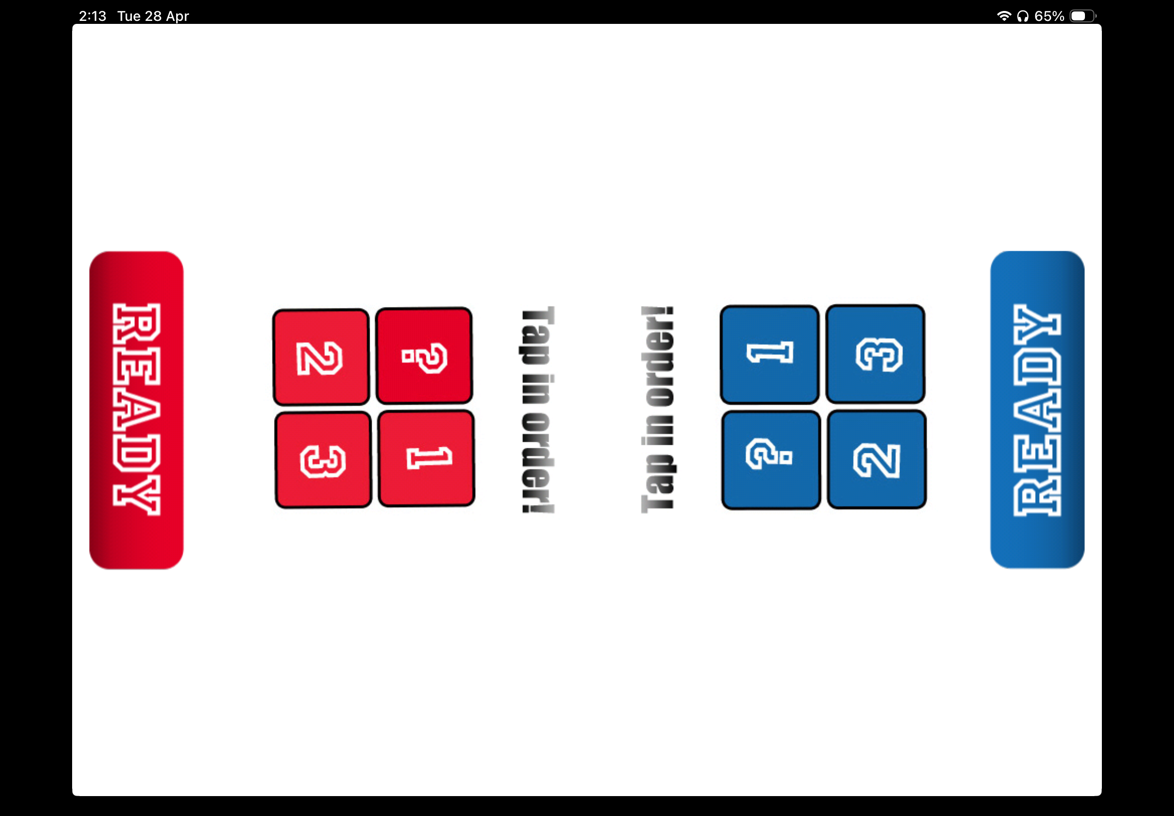
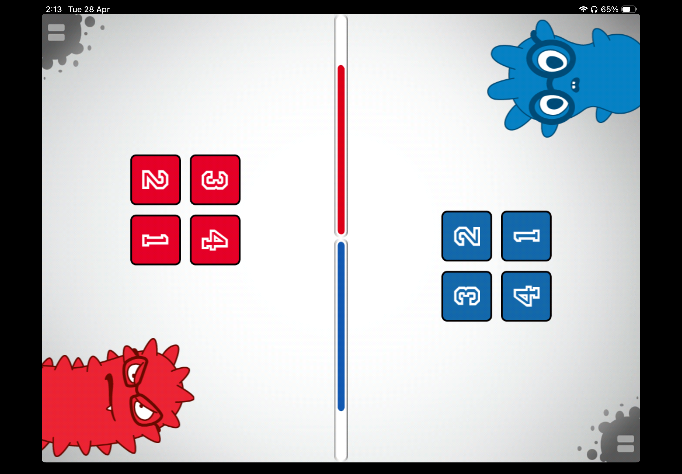
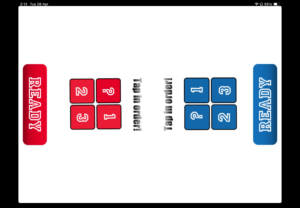
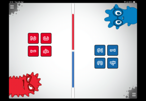
The next game is a memory game. The players are shown number cards in a random order for a short amount of time, then, they are all flipped and the players must click on them in the right order. Everytime both players get it right, the number of cards increase. If either players get it wrong, the other player wins. And if both players get it wrong, that same level is just repeated again. I plan to simulate this using Arduino by using LEDs and buttons.
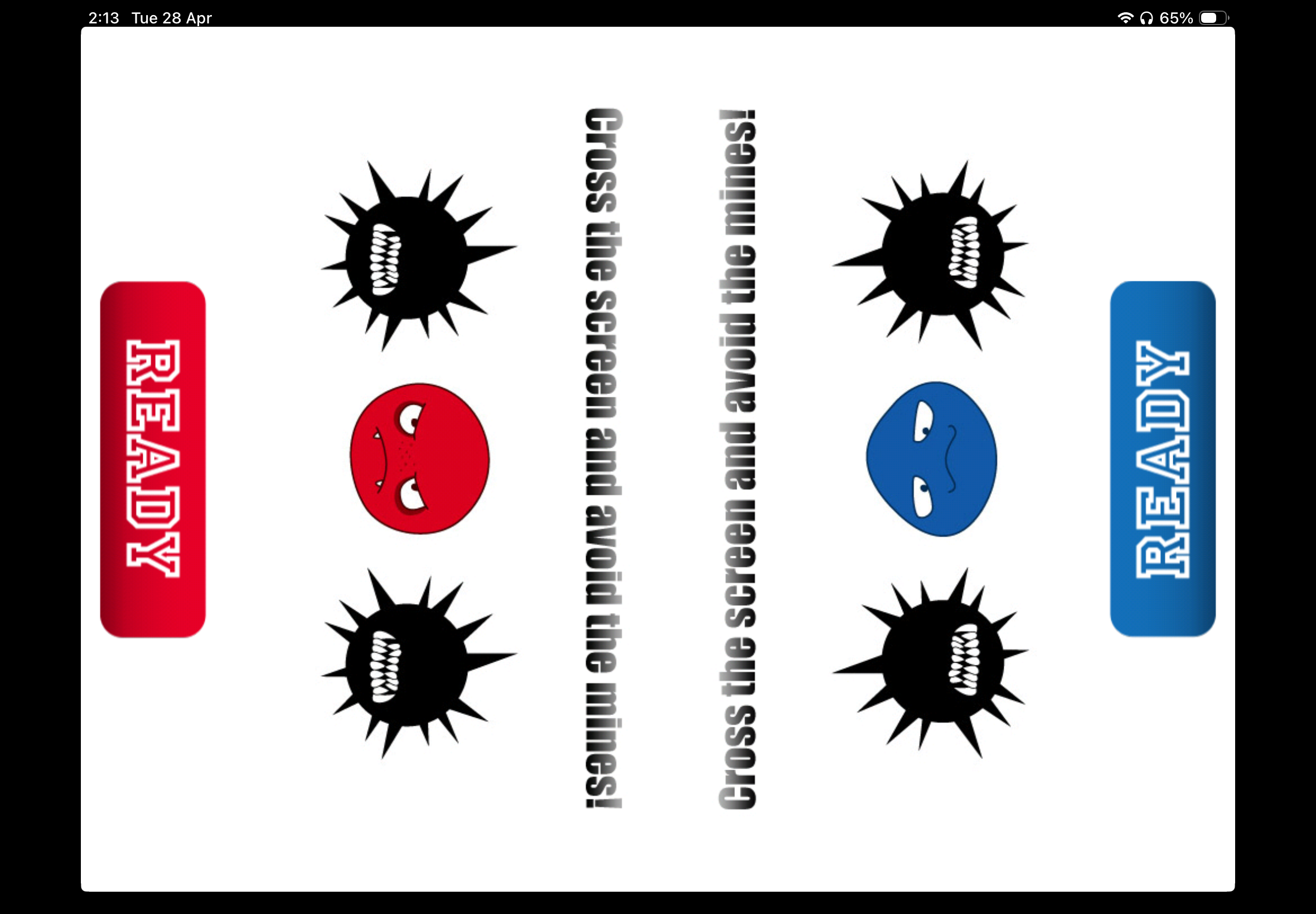
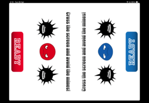
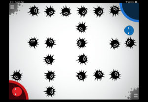
Finally, the last game is a maze. The players just have to get their virus to the other side in the fastest time and without touching the spiky black viruses. I hope to implement this in Arduino by using joystick controllers (which I would need to order).
The p5.js sketch would support the Arduino by showing the visuals for the players. Simply giving users the Arduino board would most likely be confusing, hence, I would use the p5.js screen to display instructions, as well as portray the movements the users are making using the Ardunio components. I’m planning to create a few prototypes on Canva to visualize my ideas and choose a style to go with for my final project.
At the moment, the most challenging part is the serial communication between the Arduino and the p5.js sketch. To overcome this, I’m planning to go through the notes on GitHub and complete the assignment that’s on WordPress to become more familiar with how it works.