
Serial Exercise 1
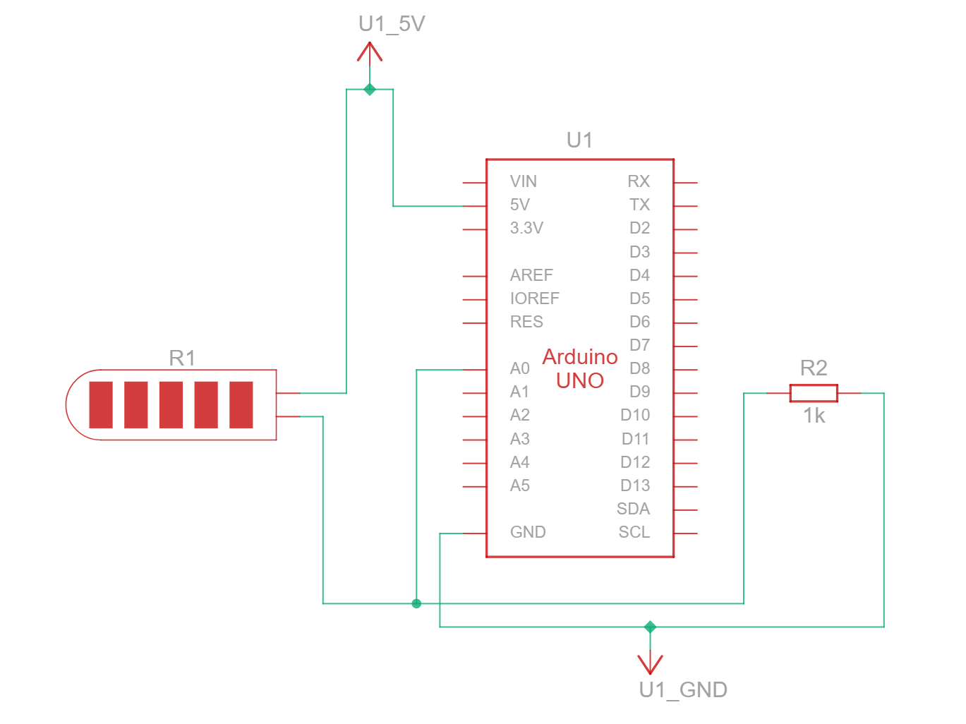
For the first exercise, we used the flex sensor in a voltage divider circuit as the analog input on pin A0 to control the x-axis motion of an ellipse on a screen. When the flex sensor is fully bent, The more a flex sensor is bent, the higher the resistance of the flex sensor.
Schematic:
p5 Sketch:
Serial Exercise 2
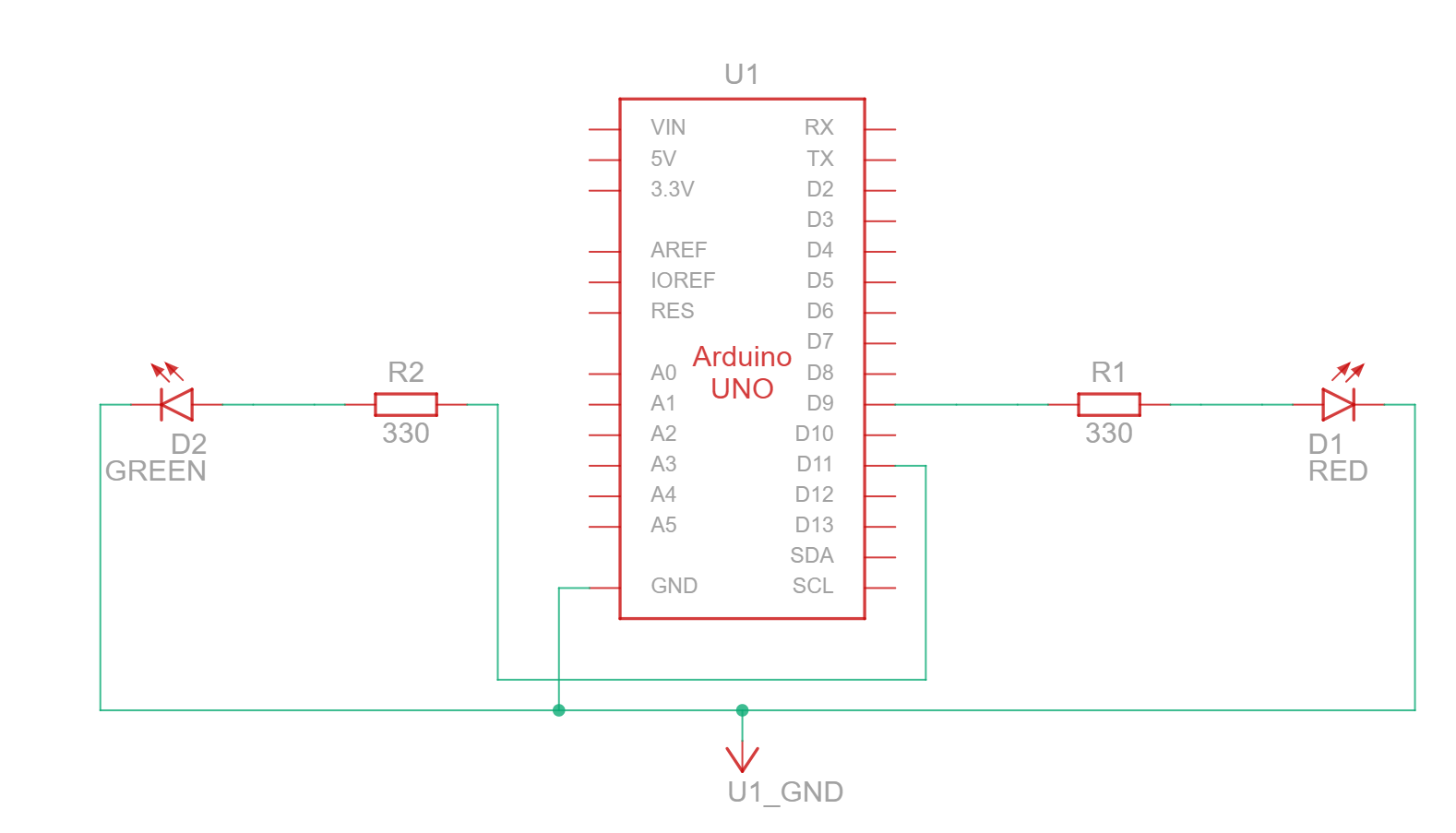
For the second exercise, we represented the movement of an ellipse along the x-axis, as controlled by mouseX, as the brightness of 2 LEDs, on pins 9 and 11. The green LED increases in brightness as the ellipse moves to the right while the red LED increases in brightness as the ellipse moves to the left.
Schematic:
p5 Sketch:
Serial Exercise 3
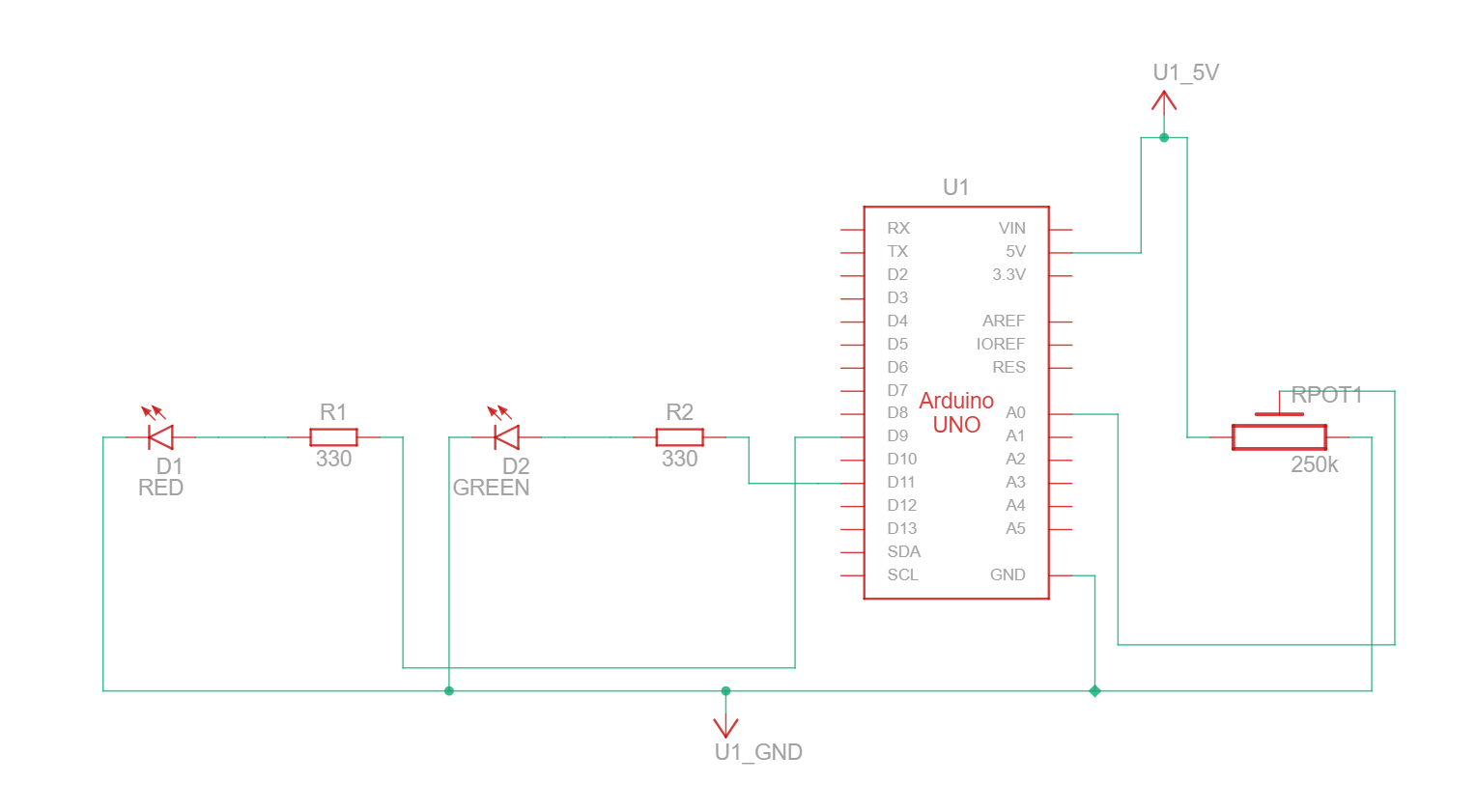
Here we edited Prof. Aaron Sherwood’s GravityWind example in p5 to connect to Arduino through Serial Communication. This allows the potentiometer on pin A0 to control wind speed and direction depending on turning of the potentiometer (0 to 1023 mapped to -5 to 5) and for the LEDs on pins 9 and 11 to blink alternately when the ball crosses the bottom end of the screen.
Schematic:
p5 sketch:
Code (for all three)
From the Arduino side, we used a common code, mainly to prevent errors from continuously updating the code. The setup() function set up serial communication and the behavior while a connection was yet to be established. The loop() function was as follows:
void loop() {
  // wait for data from p5 before doing something
  while (Serial.available()) {
    digitalWrite(LED_BUILTIN, HIGH); // led on while receiving data
    int left = Serial.parseInt();
    int right = Serial.parseInt();
    if (Serial.read() == '\n') {
      digitalWrite(leftLedPin, left);
      digitalWrite(rightLedPin, right);
      int sensor = analogRead(potPin);
      delay(5);
      Serial.println(sensor);
    }
  }
  digitalWrite(LED_BUILTIN, LOW);
}
From the p5 side, our code didn’t differ greatly from the Serial Communication template. Where our code differed was mainly in mapping analog inputs to fit the range of values of the sketch width/maximum viable wind speed (for exercises 1 and 3 respectively), while variables called ‘left’ and ‘right’ were assigned to track changes to the LED state due to changes in the sketch.
One code we were particularly proud of in Exercise 3 was how we alternated the blinking of the LEDs depending on the number of times the ball bounced.
if (position.y > height - mass / 2) {
  velocity.y *= -0.9; // A little dampening when hitting the bottom
  position.y = height - mass / 2;
  left = (left + 1) % 2;
  if (left == 0) {
    right = 1;
  } else {
    right = 0;
  }
}
The code for assigning the values to the right LED may look needlessly complicated, and it seems that both could use the (x + 1) % 2 for both LEDs, only assigning one as 0 and the other as 1 at start. However, this method allowed for both LEDs to be dark before the first bounce of each ball (which can be seen in the demo if slowed), which we felt was key to the prompt.